Table of Contents
Advertisement
Quick Links
Advertisement
Table of Contents

Related Manuals for Topcon RC-5A


Summary of Contents for Topcon RC-5A
- Page 1 SYSTEM MANUAL Remote Control System RC-5A 1010049-02-A...
- Page 2 • Some of the diagrams shown in this manual may be simplified for easier understanding. • This manual is protected by copyright and all rights are reserved by TOPCON CORPORATION. • Except as permitted by Copyright law, this manual may not be copied, and no part of this manual may be reproduced in any form or by any means.
- Page 3 S Li-ion Li-ion :This is the mark of the Japan Surveying Instruments Manufacturers Association.
-
Page 4: Table Of Contents
CONTENTS 1. PRECAUTIONS FOR SAFE OPERATION ....1 2. PRECAUTIONS ............4 3. LASER SAFETY INFORMATION ....... 8 4. ON-DEMAND REMOTE CONTROL FUNCTIONS ..9 Turning Operation Flow ........... 10 Measurement Flow ............11 5. SYSTEM CONFIGURATION ........14 Parts of the Remote Controller ........14 System Configuration of the Remote Controller .... -
Page 5: Precautions For Safe Operation
1. PRECAUTIONS FOR SAFE OPERATION For the safe use of the product and prevention of injury to operators and other persons as well as prevention of property damage, items which should be observed are indicated by an exclamation point within a triangle used with WARNING and CAUTION statements in this system manual. The definitions of the indications are listed below. - Page 6 1. PRECAUTIONS FOR SAFE OPERATION When mounting the instrument on the pole, tighten the pole-securing knob securely. Failure to tighten the knob properly could result in the instrument falling off the pole, causing injury. Do not carry the pole with the tip pointed at other persons. A person could be injured if ...
- Page 7 1. PRECAUTIONS FOR SAFE OPERATION Caution Do not touch liquid leaking from batteries. Harmful chemicals could cause burns or blisters. Bluetooth wireless technology Warning Do not use within the vicinity of hospitals. Malfunction of medical equipment could result. Use the instrument at a distance of at least 22 cm from anyone with a cardiac pacemaker.
-
Page 8: Precautions
2. PRECAUTIONS Charging Battery • The battery (BDC46C) was not charged at the factory. Charge the battery fully before using. • Be sure to charge the battery within the charging temperature range. Charging temperature range:0 to 40°C • Use only the specified battery or the battery charger. Failures caused by using other batteries or battery chargers are out of warranty including the main unit. - Page 9 Contact your local dealer in advance. "14. REGULATIONS" • TOPCON CORPORATION is not liable for the content of any transmission nor any content related thereto. When communicating important data, run tests beforehand to ascertain that communication is operating normally.
- Page 10 • TOPCON CORPORATION cannot guarantee full compatibility with all Bluetooth product on the market. Exporting this product (Relating EAR) • This product is equipped with the parts/units, and contains software/technology, which are subject to the EAR (Export Administration Regulations).
- Page 11 2. PRECAUTIONS Exceptions from responsibility • The user of this product is expected to follow all operating instructions and make periodic checks (hardware only) of the product’s performance. • The manufacturer, or its representatives, assumes no responsibility for results of faulty or intentional usage or misuse including any direct, indirect, consequential damage, or loss of profits.
-
Page 12: Laser Safety Information
3. LASER SAFETY INFORMATION Remote Controller is classified as a Class 1 Laser Product according to IEC Standard Publication 60825-1 Ed. 3.0: 2014 and United States Government Code of Federal Regulation FDA CDRH 21CFR Part1040.10 and 1040.11 (Complies with FDA performance standards for laser products except for deviations pursuant to Laser Notice No.50, dated June 24, 2007.) Laser beam is emitted from here... -
Page 13: On-Demand Remote Control Functions
4. ON-DEMAND REMOTE CONTROL FUNCTIONS The Remote Control System works as follows. A laser is emitted from the laser projection port on the Remote Controller. The total station rotates until its beam detector receives this beam. In this way the total station is able to detect the position of the Remote Controller. -
Page 14: Turning Operation Flow
4. ON-DEMAND REMOTE CONTROL FUNCTIONS Turning Operation Flow To perform Turning, follow the procedure below. For measurement procedure, see "4.2 Measurement Flow" 1. Point the Remote Controller laser projection port and prism in the direction of the total station and instruct the instrument to start Turning. -
Page 15: Measurement Flow
4. ON-DEMAND REMOTE CONTROL FUNCTIONS • The time limit for Turning is 60 seconds from the start of Turning operation. If the operation exceeds this time limit, an error occurs. • When Auto Tracking has been selected, the total station will start tracking a moving prism once Turning to that prism has been completed. - Page 16 4. ON-DEMAND REMOTE CONTROL FUNCTIONS 3. Set measurement settings for the total station and select prism type. "6. SETTINGS FOR THE TOTAL STATION" Prism selection: Operator’s Manual for your total station, "EDM Settings" 4. Check that total station Bluetooth settings are made and the instrument is ready for communication.
- Page 17 4. ON-DEMAND REMOTE CONTROL FUNCTIONS However, the time limit for Turning is 60 seconds from the start of Turning operation and if the operation exceeds this time limit, an error occurs. • Using the total station guide light when performing Turning operation allows the operator to confirm whether or not the total station has correctly located the Remote Controller laser beam.
-
Page 18: System Configuration
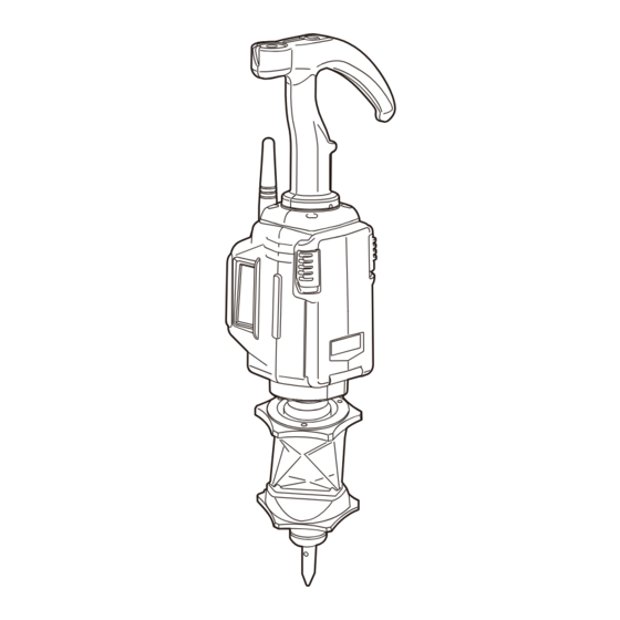
5. SYSTEM CONFIGURATION Use a total station that supports Remote Control System. "HOW TO READ THIS MANUAL Notes regarding manual style" Parts of the Remote Controller Remote Controller (RC-5A) ● Laser projection Control panel port side side Bluetooth antenna... - Page 19 Adjusting the circular level First attach the RC-Handle and 360° Prism ATP1 to the RC-5A, and then attach the RC-5A to the instrument height adapter (AP41) etc. Holding the RC-Handle, keep the instrument level. Check the position of the bubble of the circular level. If the bubble is not off-center, no adjustment is necessary.
-
Page 20: System Configuration Of The Remote Controller
5. SYSTEM CONFIGURATION System Configuration of the Remote Controller For use with other prism types, contact your local dealer. Pin Pole Type ● RC-Handle for RC-5A RC-5RH Protector Protector pole 360° Prism ATP1 Pin pole for Adapter ATP1SII SB184 pole 360°... - Page 21 5. SYSTEM CONFIGURATION Range Pole Type ● Remote Controller RC-5A Protector 360° Prism ATP1 One-touch attachment SB179B 5/8 inch Setting screw (W5/8-11) pole Range pole example ● Height to center of prism The height to the center of the prism differs as shown below depending on the selection of prism/pole combination.
- Page 22 5. SYSTEM CONFIGURATION Attaching/Releasing the One-touch attachment ● Slide the lock release button to the right then press to release the One-touch attachment. Adjusting position of 360° Prism (ATP1SII) on pin pole (PP2) ● Pressing the release button allows the prism to slide up and down the pin pole.
- Page 23 5. SYSTEM CONFIGURATION Connecting the 360° Prism to the Remote Con- ● troller Attach the 360° Prism to the Remote Controller so that the center of the Remote Controller and the sighting direction of the prism are aligned and the laser projection port is pointing in the same direction as the prism sighting direction.
-
Page 24: Settings For The Total Station
6. SETTINGS FOR THE TOTAL STATION The following settings are necessary in order to use the total station as part of the Remote Control System. For other functions and operations, see the operator's manual for your total station. For further details regarding Bluetooth communications, see "2. PRECAUTIONS Precautions concerning Bluetooth wireless technology"... - Page 25 6. SETTINGS FOR THE TOTAL STATION Set "Comms mode" to "Bluetooth". • Changing communication settings during Bluetooth communication will cancel the connection. 2. The display returns to Meas mode and total station enters "Waiting" mode. • Check that the communication status icon changed to The Remote Controller searches for the total station wireless device and initiates a connection.
- Page 26 6. SETTINGS FOR THE TOTAL STATION 6.1.2 Settings for Auto Pointing and Auto Tracking • Auto Pointing model does not support Auto Tracking. 1. Select "Obs.condition" in Config. mode and select "Search/Track" in <Obs.condition> to perform Auto Pointing/Auto Tracking settings. For Auto Pointing only set "Track Setting"...
- Page 27 6. SETTINGS FOR THE TOTAL STATION of the field-of-view, Auto Pointing is complete. Although this setting provides greater accuracy, when supporting the pole by hand, hand movements will result in Auto Pointing taking too long to complete and a "Time out" error will occur. When "Rapid"...
- Page 28 6. SETTINGS FOR THE TOTAL STATION Search pattern The search pattern is the rotating method of telescope and instrument to find the target prism in search mode. In Pattern "1" instrument starts searching the prism at the point where the prism is lost and gradually expands the searching area in vertical direction, keeping the horizontal angular width.
- Page 29 6. SETTINGS FOR THE TOTAL STATION Tracking Meas. This setting refers to angle display when performing Auto Tracking. In the "Stop&Go" setting, the angle display is stable when the target stops during Auto Tracking. The "Stop&Go" setting may help measurements in scintillation in some degree. ...
-
Page 30: Settings For Ps/Ds/Ms
6. SETTINGS FOR THE TOTAL STATION Settings for PS/DS/MS 6.2.1 Settings for Bluetooth Communication When communicating between the total station and Remote Controller using Bluetooth wireless technology, the modem for the total station will be set as the "Master" device and the total station will be set as the "Slave"... - Page 31 6. SETTINGS FOR THE TOTAL STATION 3. The display returns to Meas mode and total station enters "Waiting" mode. The Remote Controller searches for the total station wireless device and initiates a connection. "7.2 Configuring Bluetooth Connections to the Total Station" 4.
- Page 32 6. SETTINGS FOR THE TOTAL STATION Items set and options (PS) (1) AUTO AIM Fine/Rapid (2) MEAS Acc. Advanced/Standard (3) Track Setting None/Search/Track (4) Srch method G.S./R.C. (5) TURN 3"/5"/10"/20"/30"/60" Auto AIM When the target enters the field-of-view within the set limit for Auto Pointing completion (the limit differs between "Fine"...
- Page 33 6. SETTINGS FOR THE TOTAL STATION Srch method Selects search before distance measurement option. When set to "G.S." the instrument will search for the target in the area specified in the Search area tab. When set to "R.C.", the instrument will wait for a Turning command to be issued from the Remote Controller before starting Auto Pointing.
- Page 34 6. SETTINGS FOR THE TOTAL STATION 4. When necessary, set the Jog turning speed for vertical and horizontal rotation of the telescope. The "Shift" point signifies the dial turning speed at which telescope rotation switches from the Lo speed setting to the Hi speed setting.The higher the "Shift"...
-
Page 35: Performing Turning From The Total Station
6. SETTINGS FOR THE TOTAL STATION Performing Turning from the Total Station It is possible to allocate total station softkeys for both designating the Turning direction, and issuing the instruction to start Turning. For allocating softkey functions, see the Operator’s Manual for your total station. ●... - Page 36 6. SETTINGS FOR THE TOTAL STATION When "Search" is set ● "Motor" When "Search" set in "A.T. Setting" When "None" set in setting "Srch method" is G.S. "A.T. Setting" "Srch method" is R.C. Softkey (Global Search) [SRCH] Performs Auto Pointing [DIST] Performs Turning Performs Auto Pointing...
- Page 37 6. SETTINGS FOR THE TOTAL STATION When "Track" is set ● "Motor" When "Track" set in "A.T. Setting" When "None" set in setting "Srch method" is G.S. "A.T. Setting" "Srch method" is R.C. Softkey (Global Search) [SRCH] Performs Auto Pointing then Auto Tracking Performs Auto Pointing [DIST] Performs Turning...
-
Page 38: Turning Error
6. SETTINGS FOR THE TOTAL STATION Turning Error When Turning fails to detect the prism, an error occurs. When the laser beam from the Remote Controller is reflected off an unrelated object the total station completes Turning operation pointing at the object, instead of the Remote Controller. When this happens, press [RC Cont] to nullify the current measurement position and continue Turning operation. -
Page 39: Basic Operation
7. BASIC OPERATION This section explains basic operation of the Remote Controller. Using the Battery Mount the charged battery (BDC46C). When the remaining battery power becomes low, the ● POWER Flashes. Types of power source: "10.1 Power Supply System" ... -
Page 40: Configuring Bluetooth Connections To The Total Station
7. BASIC OPERATION PROCEDURE Removing the battery 1. Slide down the catches on the battery cover to open. 2. Push the battery up to release. 3. Close the battery cover. A click is heard when the cover is secure. Make sure that both catches on the battery cover have returned to their original positions. - Page 41 7. BASIC OPERATION When is displayed on the status bar of the total station companion device, the Remote Controller is currently paired to different device. Press the SEARCH button to switch the pairing from the current device to the next locally available device.
-
Page 42: Button Operations
7. BASIC OPERATION Button Operations The Remote Controller is operated using the buttons on the control panel. 7.3.1 Power ON/OFF Press the POWER button to switch ON the Remote Controller. ● POWER is Lit. Press and hold the POWER button to switch OFF the Remote Controller. -
Page 43: Communication Status
7. BASIC OPERATION • When the laser beam from the Remote Controller is reflected off a unrelated object the total station completes Turning operation pointing at this object instead of the Remote Controller. When this happens, press and hold the SEARCH button to nullify the current measurement position and continue Turning operation. -
Page 44: Calibrating The Electronic Compass
7. BASIC OPERATION Control panel status Port Flashing Searching for total COM1 Comm OK station (total station) Data collector is COM2 Comm OK searching for Remote (data collector) Controller Calibrating the Electronic Compass The onboard electronic compass was calibrated before being shipped from the factory. A function within the compass will automatically perform any necessary calibration in response to changes in the magnetic field. - Page 45 7. BASIC OPERATION 2. When calibration is necessary, switch OFF and proceed to "PROCEDURE Manually calibrating the compass". PROCEDURE Manually calibrating the compass 1. Press the POWER button while pressing the FAR button with the power switched OFF. An audio tone sounds and the Remote Controller is switched ON in calibration mode.
- Page 46 7. BASIC OPERATION 5. Hold the Remote Controller horizontal and press the SEARCH button ● FAR Flashes. 6. Without moving the position of the Remote 1m or above Controller, rotate it 1.5 to 2 times in a horizontal direction. 7. After rotating, continue to hold the Remote Controller horizontal and press the SEARCH button 8.
-
Page 47: Error Indications
8. ERROR INDICATIONS When an error occurs, the nature of the error is indicated by the condition of the LEDs on the Remote Controller. LED Condition Error Remaining battery power is low. ● POWER Flashing Replace the batteries. "7.1 Using the Battery" 3 long audio tones and the No battery power remaining. -
Page 48: Troubleshooting
9. TROUBLESHOOTING Pressing the POWER button does not switch ON the power. ● → Check that the battery has been inserted. Replace the battery. "7.1 Using the Battery" Åú The total station does not perform Turning operation even when distance measure- ment is executed. -
Page 49: Optional Accessories
10. OPTIONAL ACCESSORIES • Place the instrument in its case in accordance with the layout plan on the inside of the carrying case. • Place the data collector in its dedicated protective case before inserting into the carrying case. For use with other prism types, contact your local dealer. - Page 50 10. OPTIONAL ACCESSORIES Sliding Prism (ATP1SII) ° 360° Sliding Prism (ATP1SII)... . . 1 Pin Pole for ATP1SII (PP2) ... . . 1 Protective cover .
-
Page 51: Power Supply System
10. OPTIONAL ACCESSORIES 10.1 Power Supply System Operate your RC-5A with the following combinations of power equipment. • Never use any combination other than those indicated below. If you do, the instrument could be damaged. Those indicated by * are standard accessories. Others are optional accessories (sold separately) -
Page 52: Specifications
(Rapid (single)) Operating range of function for automatically determining rotation direction: Magnetic inclination is 80° or less and horizontal component is more than 10µT Data collector: TOPCON total station-compatible product Control panel (keyboard) 3 Keys Indicator 5 LED Audio tone Operating temperature -20 to 50°C... - Page 53 11. SPECIFICATIONS Wireless communication Transmission method: FHSS GFSK, π/4DQPSK, 8DPSK Modulation: Frequency band: 2.402 to 2.480GHz Bluetooth profile SPP, DUN Power class Class 1 Usable range 300m (No obstacles, few vehicles or sources of radio emissions/ interference in the vicinity of the instrument, no rain) 600m (Paired with GT, with instrument height to be more than 1.5m, no obstacles (like building structures, trees or vehicles) causing interrupting/reflecting radio wave, few sources of radio emissions/...
- Page 54 Prism constant 3D positioning accuracy (standard deviation) 3mm (Angles of elevation and inclination both less than 20°) Prism height 37mm (from mounting face (flange face) when attached to RC-5A) Operating temperature -20 to 50°C Storage temperature range -30 to 70°C...
-
Page 55: Explanation
12. EXPLANATION 12.1 High Accuracy with the 360° Prism Sighting can be more accurately performed by facing the 360° Prism toward the total station. When using the ATP1, the 360° Prism should be set up so that a pair of diametrically-opposed hexagonal points on its rubber flanges are aligned with the sighting direction of the total station (see the diagram below). -
Page 56: Button Operations List
13. BUTTON OPERATIONS LIST Operation Button Operation Indication POWER ON Press once ● POWER is Lit ● POWER Flashes then turns POWER OFF Press and hold When ● FAR is Off, Far Mode ● FAR is Lit press once When ● FAR is Lit, Standard Mode ●... -
Page 57: Regulations
75-1, Hasunuma-cho, Itabashi-ku, Tokyo, 174- 8580 JAPAN 243-0036 Country: JAPAN U.S.A. Representative Responsible party: TOPCON POSITIONING SYSTEMS,INC. Address 7400 National Drive Livermore, CA94551, U.S.A Telephone number: 925-245-8300 Means of conformity This device complies with part 15 of the FCC Rules, Operation is... - Page 58 14. REGULATIONS Region/ Directives/ Labels/Declarations Country Regulations California Recycling and NY, Batteries U.S.A. This Class A digital apparatus meets all requirements of Canadian Interference-Causing Equipment Regulations. Cet appareil numérique de la Class A respecte toutes les exigences du Règlement sur le matériel brouilleur du Canada. This class A digital apparatus complies with Canadian ICES-003.
- Page 59 TOPCON CORPORATION EMC-Class B Address: 75-1, Hasunuma-cho, Itabashi-ku, R&TTE-Class Tokyo, 174-8580 JAPAN Europe Representative Name: Topcon Europe Positioning B.V. Representative Director: Jim Paetz Address: Essebaan 11, 2908 LJ Capelle a/d IJssel, The Netherlands WEEE Directive This symbol is applicable to EU members states only.
- Page 60 Please see the attached address list or the following website for contact addresses. GLOBAL GATEWAY http://global.topcon.com/ © 2016 TOPCON CORPORATION ALL RIGHTS RESERVED...
Need help?
Do you have a question about the RC-5A and is the answer not in the manual?
Questions and answers