Table of Contents
Advertisement
Quick Links
A SIGNATURE CUT, TRUSTED FOR OVER 100 YEARS
SAFETY, OPERATION
& MAINTENANCE MANUAL
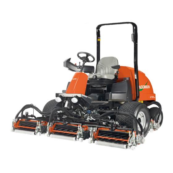
LF Series - Lightweight Fairway Mower
LF550 / LF570 – 2WD & 4WD
KUBOTA D1803-M-DI-E3B
BAU / DDF / DDG Series
KUBOTA D1803-CR-E5B
BAV / BAY / BAW / CAA Series
KUBOTA V2403-M-DI-E3B
DGL / DGQ Series
KUBOTA V2403-CR-E5B
CAD / CAE Series
KUBOTA V1505-CR-TE5
DCU / DCV / DCW / DCY Series
WARNING: If incorrectly used this machine can cause severe injury. Those who use and maintain this machine must
be trained in its proper use, warned of its dangers and must read the entire manual before attempting to set up,
operate, adjust or service the machine.
GB
United
Kingdom
WARNING
RJL AHCC
4358526-E
Advertisement
Table of Contents

Related Manuals for Jacobsen LF Series


Summary of Contents for Jacobsen LF Series
- Page 1 A SIGNATURE CUT, TRUSTED FOR OVER 100 YEARS SAFETY, OPERATION & MAINTENANCE MANUAL LF Series - Lightweight Fairway Mower LF550 / LF570 – 2WD & 4WD KUBOTA D1803-M-DI-E3B BAU / DDF / DDG Series KUBOTA D1803-CR-E5B BAV / BAY / BAW / CAA Series...
- Page 2 1Con tents This manual contains adjustment, maintenance, and Before you operate your machine, you and each operator troubleshooting instructions for your new Jacobsen you employ should read the manual carefully in its machine. This manual should be stored with the entirety.
-
Page 3: Table Of Contents
CONTENTS 1 Contents 9.10 Engine Exhaust............... 56 9.11 Diesel Particulate Filter (T4F/Stage 5 Engines Only) ..57 Introduction 9.12 Hydraulic Hoses.............. 59 2.1 Important................3 9.13 Hydraulic Fluid ..............60 2.2 Product Identification ............4 9.14 Hydraulic Filter ..............60 2.3 Serial Numbers .............. -
Page 4: Introduction
IMPORTANT ______________________________________________________________ 2Introduction The Jacobsen LF550 / LF570 with a Diesel engine is a self propelled fairway mower. The hydraulic systems are for the traction drive, steering, lift - lower and the cutting unit drive. If you follow all instructions in this manual, you increase the life of your mower and keep its maximum performance. -
Page 5: Product Identification
INTRODUCTION 2 PRODUCT IDENTIFICATION TEST ____________________________________________ Mower Serial number plate A Maximum Front Axle Load in Kg B Gross vehicle Weight in Kg West Road Ransomes Europark C Maximum Rear Axle Load in Kg Ipswich IP3 9TT England D Power in kw E Date code F Machine type (Designation) G Product code... -
Page 6: Guidelines For The Disposal Of Scrap Products
Add items that can not be easily separated into different materials to the “General discarded materials” area. • Do not burn the discarded materials Change the mower records to show that the mower is not in service and is discarded. Supply this serial number to Jacobsen Warranty Department to close their records. en-5... -
Page 7: Safety 3
Know the location and correct operation of controls. Operators without experience must receive instruction from another person that knows the correct operation of the equipment before you operate the mower. Only use parts, accessories and attachments approved by Jacobsen. 3.1.1 SAFE OPERATION _________________________________________________________ Read the Operator’s Manual and other training material. - Page 8 3 SAFETY 3.1.3 OPERATION ______________________________________________________________ Never operate the engine without enough ventilation or in an enclosed area. The carbon monoxide in the exhaust fumes can increase to dangerous levels. Never carry passengers. Keep bystanders or animals away from the mower. Disengage all drives and engage the parking brake before you start the engine.
- Page 9 ROPS. Do not remove the ROPS from the mower. Jacobsen must approve any changes to the ROPS. 3.1.5 SAFE HANDLING OF FUELS ________________________________________________ The fuel and the fuel vapors are flammable. Use caution when you add the fuel to the mower. The fuel vapors can cause an explosion.
- Page 10 Replace worn or damaged parts for safety. Replace damaged or worn labels. Only use parts, accessories and attachments approved by Jacobsen. To decrease the fire hazard, remove materials that burn from the engine, muffler, battery tray and fuel tank area.
- Page 11 4. Never carry passengers. 5. Never operate the equipment without a correctly fastened grass deflector in position. If additional information or service is needed, contact your Authorized Jacobsen Dealer. Your Dealer knows the current methods to service this equipment. en-10...
-
Page 12: Specifications
4 SPECIFICATIONS ENGINE SPECIFICATIONS __________________________________________________ 4Specifications Make Kubota Tier 4 Interim (T4I) Engine Tier 4 Final/Stage V (T4F/Stage 5) Engines Model D1803-M-DI-E3B V2403-M-DI-E3B D1803-DICR-E4B V2403-DICR-E4B/E5B V1505-CR-TE5 Type Four cycle, liquid cooled, Diesel Number of Cylinders Bore and 3.43 in. (8.7 cm) x 4.03 in. (10.24 cm) 3.07 in (78mm) X 3.09 Stroke in (78.4mm) -
Page 13: Dimensions And Weights
SPECIFICATIONS 4 DIMENSIONS AND WEIGHTS ________________________________________________ LF550 / LF570 A - Width of Cut 100 inch (254.0 cm) B - Maximum Width 115 inch (292.1 cm) C - Transport Width 87 inch (220.9 cm) D - Height ROPS frame in the vertical position 88 inch (223.5 cm) E - Height ROPS frame folded 61 inch (155.2 cm) - Page 14 4 SPECIFICATIONS A (LF550 / LF570) B (LF550 / LF570) en-13...
-
Page 15: Mower Specification
SPECIFICATIONS 4 MOWER SPECIFICATION ___________________________________________________ Battery: 12V, 600 CCA, Group BCI 24 Service Brake: Dynamic braking through the traction circuit Parking Brake: Integrated in wheel motor, hydraulic release Fuel Tank: 17 U.S. Gallons (65 l) Hydraulic Tank: 14 U.S. Gallons (53 l) Hydraulic Fluid: GreensCare 68 Return Filter:... - Page 16 Jacobsen LF570 104 dB(A) ± 1.24 LWA D1803 Engine Speed 2859 rpm Jacobsen LF550 103 dB(A) ± 1.24 LWA V1505 Engine Speed 2946 rpm Measured Sound Pressure level: Jacobsen LF570 87dB(A) ± 1.24 Leq V2403 Engine Speed 2839 rpm ( Representing worse case configuration) en-15...
-
Page 17: Slopes
SPECIFICATIONS 4 SLOPES _________________________________________________________________ DO NOT USE ON SLOPES GREATER THAN 18.3°. The 18.3° slope was calculated with static stability measurements according to the requirements of BS EN ISO 5395-3. CUTTING UNIT SPECIFICATION ______________________________________________ LF550 / LF570 Blade Length 22 in. (55.9 cm) Number of cutting units LF550 Height of cut 3/8 to 3/4 in. -
Page 18: Accessories
4 SPECIFICATIONS ACCESSORIES ___________________________________________________________ 4.9.1 LF550/LF570 CUTTING UNITS _______________________________________________ Left Hand 7 Blade Reel 62839 (3 Required) Right Hand 7 Blade Reel 62840 (2 Required) Left Hand 9 Blade Reel 62855 (3 Required) Right Hand 9 Blade Reel 62856 (2 Required) Left Hand Vertical Mower 67894 (3 Required) Right Hand Vertical Mower 67895 (2 Required) 4.9.2 LF570/LF570 CUTTING UNITS _______________________________________________... -
Page 19: Support Literature
LED Light Kit (One Light) : 4238642 4.10 SUPPORT LITERATURE ____________________________________________________ Contact your Jacobsen Dealer for a complete listing of literature available for your mower. Safety, Operation, & Maintenance Manual: 4358526 Mower Parts Manual: 4358527 Tier 4 Final / Stage 5 D1803 / V2403 Engine Parts Manual: 4299117 Tier 4 Interim Engine Parts Manual: 4358529 Service &... -
Page 20: Labels
5 LABELS SAFETY LABELS__________________________________________________________ 5Labels Understand the purpose of these labels. The labels are important to the safe operation of the mower. REPLACE THE DAMAGED labels IMMEDIATELY. DANGER To prevent injury while you do work on the battery: Connect the negative (BLACK) wire after the positive (RED) wire. - Page 21 LABELS 5 Read the Manual.WARNING Always use the seat belt with the ROPS frame in the vertical and locked position. 5002952 4326718 WARNING • Read the manual. Do not allow anyone without training to use the mower. • Keep the shields in position and hardware fastened. •...
- Page 22 5 LABELS NOTICE DO NOT USE START ASSIST FLUIDS Start assist fluids in the air intake system can be explosive or cause an engine condition that is not controlled and can cause engine damage. 4181861 WARNING Do not use on slopes greater than 18° 18°+ 4326713 WARNING...
-
Page 23: Instruction Labels
LABELS 5 INSTRUCTION LABELS _____________________________________________________ Traction pedal operation 3008521 Backlap Label Rotate knob to set backlap speed. 3008683 Tow valve operation 3008682 en-22... -
Page 24: Controls
6 CONTROLS OPERATOR COMPARTMENT ________________________________________________ 6Con trols Tier 4 Interim Engine Tier 4 Final / Stage 5 Engine en-23... -
Page 25: Armrest
CONTROLS 6 ARMREST ________________________________________________________________ 6.2.3 6.2.10 6.2.8 6.2.4 6.2.2 6.2.1 6.2.7 ® 6.2.5 6.2.6 6.2.9 en-24... - Page 26 6 CONTROLS 6.2.1 IGNITION SWITCH _________________________________________________________ The ignition switch has three positions, OFF, RUN and START. In the RUN position, the controller program is active and input and output circuits are monitored. START 6.2.2 PARKING BRAKE SWITCH __________________________________________________ To engage the parking brake, press the front of the switch. Parking brake light on LDU (See 6.2.9) will turn on.
- Page 27 CONTROLS 6 6.2.4 PTO SWITCH _____________________________________________________________ The PTO switch is a 2-position switch to engage and to disengage the cutting units. The PTO switch must be in the OFF position to start the engine. Press the front part of the switch to move the switch to the ON position. When the PTO switch is in the ON position, the light in the switch is on, the cutting units are engaged and the joystick is set to automatic mode.
- Page 28 6 CONTROLS 6.2.7 JOYSTICK _______________________________________________________________ The joystick controls the cutting units lift and lower. The joystick operates in automatic or manual mode. Push the joystick to lower the cutting units or pull the joystick to lift the cutting units. Manual Mode - Set the PTO switch in the OFF (down) position to set the joystick in manual mode.
- Page 29 CONTROLS 6 6.2.9 12 VOLT ACCESSORY OUTLET ______________________________________________ The 12 Volt accessory outlet found inside the armrest storage tray supplies power to 12 Volt accessories. Only use the 12 Volt outlet with the engine started to prevent a drained battery. 12 VOLT CAUTION The 12 Volt accessory outlet is protected by a 10-Amp fuse.
-
Page 30: Ldu
The LDU operates in one of two modes, Operator Mode (Normal Operation) and JACOBSEN Maintenance Mode. The use of Maintenance Mode needs a four digit pin number. See Section 9.2 for... - Page 31 CONTROLS 6 The red hydraulic-level light indicates a low-fluid level in the hydraulic tank. Immediately stop the engine. Visually inspect the mower for indications of leaks around connections, hoses and hydraulic components. Return the mower to the service area for maintenance. WARNING The hydraulic fluid is under pressure.
- Page 32 6 CONTROLS 6.3.2 ALARM SCREENS_________________________________________________________ There are six alarm screen displays to tell the operator or technician of a problem that must be corrected. When the engine oil pressure is less than 7 psi (0.48 BAR), the Low Oil Pressure screen is LOW OIL shown on the LDU.
- Page 33 To enter Maintenance Mode, press the LDU button until the ENTER PIN screen is shown on the LDU. Use the joystick to change the numbers and the LDU button to move to the next number. When the correct pin is entered, Maintenance Mode is active. See Section 9.2 for Maintenance Mode. JACOBSEN LDU-A MCU-A...
-
Page 34: Traction Pedal
6 CONTROLS TRACTION PEDAL_________________________________________________________ The traction pedal controls the movement of the mower. Press the front of the pedal to move in the forward direction. Press the rear part of the pedal to move in the reverse direction. When traction Forward pedal is not pressed, the pedal will return to the NEUTRAL position. -
Page 35: Throttle Lever (T4I Engines Only)
CONTROLS 6 6.6.2 PREMIUM SEAT CONTROLS ________________________________________________ The seat has four controls to adjust for the operator. WARNING To prevent injuries, DO NOT adjust the seat while you operate the mower. Only adjust the seat with the mower stopped and parking brake engaged. -
Page 36: Operation
7 OPERATION DAILY INSPECTION________________________________________________________ 7Operation CAUTION The inspection must be done each day when the engine is turned off and all fluids are cold. Lower the cutting units to the ground, engage the parking brake, stop the engine and remove the ignition key. Do a visual inspection of the mower. -
Page 37: Interlock System
OPERATION 7 INTERLOCK SYSTEM ______________________________________________________ The Interlock System prevents the engine from starting unless the parking brake switch is in the ON position, the traction pedal is in the NEUTRAL position and the PTO switch is in the OFF position. The system stops the engine if the operator leaves the seat with the PTO switch in the ON position, traction pedal out of the NEUTRAL position or the parking brake switch in the OFF position. -
Page 38: Operating Procedure
7 OPERATION OPERATING PROCEDURE __________________________________________________ WARNING This mower has a folding Roll Over Protection Structure (ROPS). Always wear the seat belt with the ROPS frame in the vertical and locked position. Never wear the seat belt with the ROPS in the folded position. If the mower is over turning and the ROPS is in the vertical and locked position, hold the steering wheel. -
Page 39: Starting The Engine
OPERATION 7 STARTING THE ENGINE ____________________________________________________ Start the engine with the operator in the seat, the PTO switch in the OFF position and the parking brake switch in the ON position. Remove your foot from the traction pedal. Always wear the seat belt with the ROPS frame in the vertical and locked position. -
Page 40: Driving
7 OPERATION DRIVING _________________________________________________________________ Read and follow all safety instructions contained in this manual when you drive the mower. When you operate in the reverse direction, look behind you to make sure you have a clear path. IMPORTANT: Equipment must meet the current regulations to be driven on the public roads. Push the PTO switch to the OFF position and lift the cutting units to the transport position. -
Page 41: Mowing On Slopes
OPERATION 7 MOWING ON SLOPES ______________________________________________________ The mower is made to have good traction and to have good balance. Operate the mower with caution when you drive on a gradient. If you drive on wet grass, the traction and steering control of the mower is decreased. - Page 42 7 OPERATION How to calculate a slope: Tools Required: Level (A), either 1 yard, or 1 meter long. Tape measure (B). Use the level (A) and position it horizontally to measure the distance (C) with tape measure (B). Use the chart to calculate the slope angle or the percentage grade of the slope (D).
-
Page 43: Towing The Mower
NOTICE When you tow the mower, do not drive more than 2 mph (3.2 km/hr). Jacobsen recommends that you do not tow Release the mower for long distances. Position... -
Page 44: Maintenance And Lubrication Charts
8 MAINTENANCE AND LUBRICATION CHARTS MAINTENANCE CHART 8Maintenan ce and Lub ricatio n Charts Mower Service Interval Chart Interval Item Section First 50 Hours • Replace engine oil See Section 9.4 See Section 9.4 • Replace engine oil filter • Replace hydraulic oil filter See Section 9.14 •... -
Page 45: Lubrication Chart
MAINTENANCE AND LUBRICATION CHARTS 8 LUBRICATION CHART______________________________________________________ FLUID REQUIREMENTS ____________________________________________________ Fluid Requirements Quantity Type Engine Oil with Filter V2403 7.5 Quart (7.1 liter) 10W-30 API Classification CJ-4 Engine Oil with Filter D1803 5.5 Quart (5.2 liter) 10W-30 API Classification CJ-4 Engine Oil with Filter V1505 5.3 Quart (5 liter) 10W-30 API Classification CJ-4... -
Page 46: Maintenance
Neutral position to enter Maintenance Mode. NOTE: The Maintenance Mode PIN can be changed to a different number. Contact your Jacobsen Dealer or Jacobsen Technical Support at (1-800-848-1636 Option 2) for instructions. en-45... - Page 47 MAINTENANCE 9 9.2.1 MAXIMUM MOW SPEED ____________________________________________________ To set the maximum mow speed, press forward or backward on the joystick until the SET MAX MOW SPEED? screen is shown on the LDU. Press the LDU button to enter SET MAX the set mode.
- Page 48 9 MAINTENANCE 9.2.6 SWITCH STATUS__________________________________________________________ Shows the current switch settings to identify a possible problem with the switch. A status of 0 SWITCH STATUS indicates the switch is in the OFF position. A status of 1 indicates the switch is in the ON 0100 0100 position.
-
Page 49: Engine
• Refer to the Engine manual for specified maintenance intervals. If the injection pump, injectors or the fuel system need service, contact your Jacobsen Dealer. NOTICE The mower operates and cuts correctly at the preset governor setting. Do not change the engine governor setting or over speed the engine. -
Page 50: Engine Oil
9 MAINTENANCE ENGINE OIL ______________________________________________________________ Check engine oil level Check the engine oil level before you start the engine or at least five minutes after you stop the engine. Park the mower on a level surface. Remove the dipstick, clean the dipstick with a cloth and replace in position. -
Page 51: Engine Air Filter
MAINTENANCE 9 ENGINE AIR FILTER________________________________________________________ Check the service indicator each day. If the red band become visible in the window, replace the filter elements. Dust Valve Do not remove the elements to inspect or clean. Removal of Filter Housing the filter that is not necessary increases the risk of dust and other particles to enter the engine. -
Page 52: Fuel System
9 MAINTENANCE FUEL SYSTEM ____________________________________________________________ Water Separator (T4F/Stage 5 Engine Only) Tier 4 Final & Stage Engine Fuel Routing Hand If the water is not removed from the fuel, damage to the Pump fuel-injection system can occur. When the WATER IN Vent FUEL screen is shown on the LDU or every 100 hours, Vent... -
Page 53: Battery
MAINTENANCE 9 BATTERY ________________________________________________________________ Before you service the battery, make sure the ignition switch is in the OFF position and the key is removed. CAUTION When you service the battery, always use the tools with insulation, wear protective glasses and protective clothing. Discard used batteries as shown in your local regulations. -
Page 54: Charge The Battery
9 MAINTENANCE CHARGE THE BATTERY __________________________________________________________ WARNING Charge the battery in an area with good airflow. The battery can release hydrogen gas that is explosive. To prevent an explosion, keep any device that can cause sparks or flames away from the battery. When the battery charger is turned on, to prevent injury, stay away from the battery. -
Page 55: Diesel Particulate Filter (T4F/Stage 5 Engines Only)
MAINTENANCE 9 9.11 DIESEL PARTICULATE FILTER (T4F/STAGE 5 ENGINES ONLY) ____________________ During the operation of the mower, the level of particle material will increase in the Diesel Particulate Filter (DPF) system. The periodic Regen of the DPF system is needed to remove particle material. During an Active or Parked Regen, the engine will use more fuel. - Page 56 9 MAINTENANCE Parked Regen State - When a Parked Regen is needed, the Regen Request light will flash and the Tier 4 Service JACOBSEN LDU-A MCU-A Message screen is shown on the LDU. Park the mower on concrete or gravel to prevent damage to the turf.
- Page 57 MAINTENANCE 9 A Regen cycle that is not completed will move the engine through six different levels of control. Level 0 - Normal operation of mower with Passive Regen. When particles reach the Active Regen level, the engine controller will change to Level 1. When the engine controller is at Level 0, the Active and Parked Regen is disabled. Level 1 - Engine will enter Active Regen state unless the REGEN INHIBITED screen is shown on the LDU.
-
Page 58: Hydraulic Hoses
9 MAINTENANCE 9.12 HYDRAULIC HOSES ______________________________________________________________ WARNING To prevent injury from the hot, high pressure oil, never use your hands to check for oil leaks. Use the paper or cardboard to find leaks. The hydraulic fluid pressure can have enough force to enter your skin. If hydraulic fluid has entered your skin, a doctor must remove the hydraulic fluid surgically within a few hours or gangrene can occur. -
Page 59: Hydraulic Fluid
MAINTENANCE 9 9.13 HYDRAULIC FLUID ________________________________________________________ Drain and replace the hydraulic oil if one of the following occur. • Component failure • Water or foam is in the hydraulic fluid • The hydraulic fluid has a rancid odor (indication of high heat) •... -
Page 60: Wheel Mounting Procedure
Check and tighten the engine fan belt every 100 hours and replace the belt every 500 hours. Replace the clamps and hoses every two years. Have your Jacobsen Dealer check the cooling system if you need to add coolant more than one time a month or you add more than a quart of coolant at a time. -
Page 61: Folding Rops
MAINTENANCE 9 9.18 FOLDING ROPS ___________________________________________________________ A folding Roll Over Protective Structure (ROPS) is included with this mower. Inspect the ROPS periodically for loose hardware or damage. CAUTION Keep the ROPS hardware correctly fastened. Do not do welding operations, drill, change or bend the ROPS. Replace damaged ROPS. -
Page 62: To Backlap The Reels
9 MAINTENANCE 9.19 TO BACKLAP THE REELS __________________________________________________ WARNING To prevent injury, keep hands, feet and clothing away from rotating reels. Never operate the engine without enough ventilation or in an enclosed area. The carbon monoxide in the exhaust fumes can increase to dangerous levels. Check the reel and the bedknife to determine if backlapping or 7 Gang Rear Reel grinding will restore the cutting edge. - Page 63 MAINTENANCE 9 Important: The speed control valves limit reverse speed only. Once the desired reverse speed has been set the valves can remain in this position for normal mowing. If full reverse speed is needed, for instance during operation of vertical mowers, the valve can be fully closed (turn clockwise).
-
Page 64: Electrical System
• Check the interlock system, fuses and circuit breakers at normal intervals. If the interlock system does not operate correctly and you can not correct the problem, contact an authorized Jacobsen Dealer. • Keep the wiring harness away from hot surfaces and moving parts. - Page 65 MAINTENANCE 9 T4I Engines: A circuit breaker, five fuses and two relays found by the controllers and on the fuel tank are used to protect the mower circuits. NOTICE For factory help with controller problems, give the hardware revision and software version found on the controller. The replacement controllers with higher revision levels will be compatible.
-
Page 66: Care And Cleaning
Clean all plastic or rubber parts with a weak soap solution or use commercially available rubber cleaners. To keep the original high polish of the fiberglass parts, wax with a good grade of one-step cleaner wax. Repair damaged metal surfaces and use Jacobsen touch-up paint. Apply wax to the equipment for maximum paint protection. -
Page 67: Mower Storage
MAINTENANCE 9 9.22 MOWER STORAGE ________________________________________________________ General • Clean the mower and lubricate. Repair and paint damaged or open metal. • Inspect the mower, tighten all hardware, replace worn or damaged components. • Drain and fill the radiator. • Clean the tires and keep the mower so that the load is not on the tires. If the mower is not on the jack stands, check tires at normal intervals and add air when needed. -
Page 68: Adjustments
Always use the jack stands. A qualified technician must always do adjustments and maintenance. If the correct adjustments can not be made, contact your Jacobsen Dealer. Inspect the equipment according to the maintenance schedule and keep complete records. Keep the equipment clean. -
Page 69: Steering Adjustment
ADJUSTMENTS 10 10.3 STEERING ADJUSTMENT ___________________________________________________ Steering Toe-In Adjustment Turn the rear wheels to the straight position. Tie Rod Loosen the jam nuts on both ends of the tie rod. Rotate the tie rod to get the correct toe-in. the Toe- in must not be more than +1/16 inch (+ 0.15 cm). -
Page 70: Armrest Height Adjustment
10 ADJUSTMENTS 10.5 ARMREST HEIGHT ADJUSTMENT ___________________________________________ The armrest has four available height settings for the operator. To adjust standard seat armrest height: Stop the engine and remove the key. Remove the armrest hardware from the bracket on Armrest the right side of the seat. Hardware Lift or lower the armrest as needed until another set of holes in the armrest bracket align with the seat... -
Page 71: Armrest Pivot
ADJUSTMENTS 10 10.6 ARMREST PIVOT __________________________________________________________ 1. Adjust the plunger as required so that the plunger button stops the armrest at both ends of armrest pivot slots. The plunger body must not contact the armrest pivot. Do not use the plunger to increase the pivot tension. -
Page 72: Bedknife Adjustment
10 ADJUSTMENTS 10.8 BEDKNIFE ADJUSTMENT __________________________________________________ Read Section 10.7 before you adjust the reel. LF570 / LF577 Start the adjustment at the leading end of the reel, Reel Adjuster followed by the trailing end. The leading end of the reel blades is that end which moves over the bedknife first during normal reel rotation. -
Page 73: Down Pressure
ADJUSTMENTS 10 10.10 DOWN PRESSURE_________________________________________________________ Each reel has a down pressure spring. Down pressure 8-15/16 in. improves the cutting quality by contact between the reel Ball (22.7 cm) and ground. Check and adjust the down pressure any Joint time the HOC is changed or to improve the cut for the best performance. -
Page 74: Flash Attach
10 ADJUSTMENTS 10.11 FLASH ATTACH _________________________________________________________ ™ Installing Cutting units Put each cutting unit in front of the lift arm. Lift the lift arm and put the cutting unit so that the yoke is aligned to the swivel housing. Carefully lower the lift arm on the yoke. -
Page 75: Bedknife Adjuster Spring
ADJUSTMENTS 10 10.12 BEDKNIFE ADJUSTER SPRING ______________________________________________ For correct operation, the bedknife adjuster spring must be compressed to 1-7/16 to 1-1/2 in. (3.65 to 3.8 cm). To adjust the spring compression, loosen or tighten the locknut to get 1-7/16 to 1-1/2 in. a distance of 1-7/16 to 1-1/2 in. -
Page 76: Torque Specification
Jacobsen uses Grade 5 (Inch) and Grade 8.8 (Metric) Plated bolts, unless a note is given. Always check the marks on the head of the bolts for the bolt grade. For tightening plated bolts, use the value given for lubricated. -
Page 77: Problem Solving 11
11.1 GENERAL ________________________________________________________________ 11Prob lem Solving The problem solution chart lists basic problems that can occur during start and operation of the mower. For complete information about the hydraulic and electrical systems, contact your Jacobsen Dealer. Problem Possible Cause Action Parking brake switch OFF, traction Check the interlock and start procedure. -
Page 78: Controller
11 PROBLEM SOLVING 11.2 CONTROLLER ____________________________________________________________ The Mower Controller is a solid state device that monitors and controls the electrical functions of the mower. The controller receives the input signals from switches and sensors in the mower. The controller sends the output signals to operate relays, solenoids and warning lights. -
Page 79: Quality Of Cut 12
QUALITY OF CUT 12 12.1 QUALITY OF CUT PROBLEM SOLVING________________________________________ 12Quality of Cut Make a “test cut” to check the performance of the mower before you start the repairs. This area must have turf conditions that are known and do not change across the area. This type of area allows an accurate inspection of the perfomance of the mower to be made. -
Page 80: Marcelling
12 QUALITY OF CUT 12.3 MARCELLING ____________________________________________________________ Marcelling is a repeated pattern of different cutting heights, that causes an appearance that is like a wave. In most cases, the wave tip-to-tip distance is 2 in. (5 cm) or less. NOTE: Arrow indicates direction of travel. Probable Cause Remedy The cut (ground) speed is higher than normal. -
Page 81: Step Cutting
QUALITY OF CUT 12 12.4 STEP CUTTING____________________________________________________________ Step cutting occurs when grass is cut higher on one side of a cutting unit than the other side. Step cutting can occur when one cutting unit is higher than another cutting unit. The wear of mechanical parts or an incorrect roller adjustment can cause step cutting. -
Page 82: Scalping
12 QUALITY OF CUT 12.5 SCALPING _______________________________________________________________ Scalping is a condition in which areas of grass are cut shorter than the adjacent areas. The area can be light green or brown. A low HOC setting or turf that is not level can cause scalping. -
Page 83: Stragglers
QUALITY OF CUT 12 12.6 STRAGGLERS ____________________________________________________________ Stragglers are separated blades of grass that are not cut, or are cut incorrectly. NOTE: Arrow indicates direction of travel. Probable Cause Remedy Edge of the cutting blade(s) are not sharp. Sharpen the blade(s). The bedknife is not adjusted correctly. -
Page 84: Streaks
12 QUALITY OF CUT 12.7 STREAKS ________________________________________________________________ A streak is a line of grass that is not cut. The cause of a streak can be a damaged blade. NOTE: Arrow indicates direction of travel. Probable Cause Remedy The bedknife is damaged. Replace the bedknife. -
Page 85: Windrowing
QUALITY OF CUT 12 12.8 WINDROWING ____________________________________________________________ Windrowing is the deposit of clippings increased at one end of cutting unit(s) or between cutting units. Windrowing can make a line in the direction of travel. NOTE: Arrow indicates direction of travel. Probable Cause Remedy The grass is higher than the level at which the mower... -
Page 86: Rifling Or Tramlining
12 QUALITY OF CUT 12.9 RIFLING OR TRAMLINING __________________________________________________ Rifling or tramlining is a pattern of different cutting heights that gives the grass an appearance like a wave. This appearance is normally because of heavy contact points across a reel and bedknife. NOTE: Arrow indicates direction of travel. -
Page 87: Mismatched Cutting Units
QUALITY OF CUT 12 12.10 MISMATCHED CUTTING UNITS ______________________________________________ Mismatched cutting units is a pattern of different cutting heights, that gives the grass a stepped cut appearance. This appearance is normally because of a mismatched HOC (height-of-cut) adjustment from one cutting unit to another unit. - Page 88 Health & Safety Management Cert No. FS609275 Cert No. EMS609276 Cert No. OHS609277 United Kingdom Ransomes Jacobsen Limited West Road, Ransomes Europark, Ipswich, IP3 9TT English Company Registration No. 1070731 T: +44 1473 270000 W: www.ransomes.com Europe office Ransomes Jacobsen France...
Need help?
Do you have a question about the LF Series and is the answer not in the manual?
Questions and answers