Table of Contents
Advertisement
Quick Links
CNX-I-O_100160920_2000001478_Rev F
REMOTE CONNECT
INSTALLATION & OPERATION
INSTRUCTIONS
Models: FTXL, Knight, Armor,
& Shield
⚠ WARNING
This manual must only be used by a
qualified heating installer / service
technician. Read all instructions,
including
this
manual,
the
Installation and Operation Manuals,
and the Service Manuals, before
installing.
Perform steps in the
order given. Failure to comply could
result in severe personal injury, or
substantial property damage.
Save this manual for future reference.
Advertisement
Table of Contents

Summary of Contents for Lochinvar CON-X-US FTXL
- Page 1 CNX-I-O_100160920_2000001478_Rev F REMOTE CONNECT INSTALLATION & OPERATION INSTRUCTIONS Models: FTXL, Knight, Armor, & Shield ⚠ WARNING This manual must only be used by a qualified heating installer / service technician. Read all instructions, including this manual, Installation and Operation Manuals, and the Service Manuals, before installing.
-
Page 2: Table Of Contents
Device Registration ..............10-15 Introduction The information contained in this manual provides general guidelines for the implementation of the CON·X·US remote communication device with Lochinvar boilers. Now from virtually anywhere you can: • Monitor boiler plant operating conditions at unlimited locations •... -
Page 3: Con·x·us Installation
Installation and Operation Instructions CON·X·US Installation Table 2A - List of kit components WARNING ⚠ KB/WH/ Warning: Electrical Shock Hazard -- For FTXL Material KH/AW Description your safety, turn OFF electrical power supply Number before making any electrical connections to avoid possible electric shock. -
Page 4: Installation Procedure
Installation and Operation Instructions CON·X·US Installation Table 2B - List of bracket kits Installation procedure 1. Using four (4) 100328008 screws and four (4) 100134696 Part # Description nuts, install the plate onto the bezel. 100265396 KIT,BRKT,BEZEL,CONXUS,KB 2. Using four (4) 100134696 nuts, install the CON-X-US board with standoffs onto the plate. - Page 5 Installation and Operation Instructions CON·X·US Installation (continued) Figure 2-2B_Install WH CON·X·US Board REMOVE BEZEL 8X NUT, LOCK, 6-32 X .178, STL, ZINC PLATE, CON•X•US, BOARD CON•X•US BOARD 4X SCREW, PHP, 6-32 X 3/8 STL 2000629442 00 REMOVE FRONT DOOR NOTE: On units purchased after Serial #1915 the bezel bracket will not be required. If purchased between Serial #H10 to D15 the bezel bracket (see Table 2B on page 4) is required.
- Page 6 Installation and Operation Instructions CON·X·US Installation Figure 2-2D_Install AW CON·X·US Board 4X NUT, LOCK, 6-32 X .178, STL, ZINC CON•X•US BOARD REMOVE BEZEL PLATE, CON•X•US, BOARD 4X SCREW, PHP, 6-32 X 3/8, 4X NUT, LOCK, 6-32 X .178, STL, ZINC REMOVE FRONT DOOR 2000629473 00 Figure 2-2E_Install SNR CON·X·US Board...
- Page 7 Installation and Operation Instructions CON·X·US Installation (continued) Figure 2-3_Wiring Schematic...
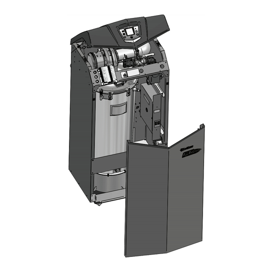
- Page 8 Installation and Operation Instructions CON·X·US Installation Installation procedure SWA/R Models Only 1. Turn OFF the main power and gas supply to the unit. 2. Remove the upper front bezel by removing the six (6) thumb screws from around the bezel (FIG. 2-4). 3.
- Page 9 Installation and Operation Instructions CON·X·US Installation (continued) 4. Install the board and bracket assembly onto the heat exchanger frame in the appropriate location as shown in FIGs 2-5C and 2-5D. 5. Disconnect the ribbon cable from the control board and route it to the ribbon cable plug on the CONXUS board labeled 6.
-
Page 10: Con·x·us Registration
Installation and Operation Instructions CON·X·US Registration The screens depicted in this manual are to be used for illustration purposes only. NOTICE Device Registration 1. Search for the CON·X·US board just like you would search for a Wi-Fi connection on your device. The LED light on the board will alternately flash blue and green when it is ready to connect. - Page 11 Installation and Operation Instructions CON·X·US Registration (continued) 3. Once connected to the CON·X·US board, you should be redirected to a Login page. Note: If you are not redirected, open your internet browser and type 10.231.277.81 in the address bar and click GO. At this point, you are choosing the network you would like the CON·X·US board to be linked with.
- Page 12 Installation and Operation Instructions CON·X·US Registration 5. Your screen should tell you when the WiFi connection is complete. The LED is constantly cyan when connected. Figure 3-4_Connection Complete 10.231.277.81 6. Download the Android App on Google Play or the Apple App from the App Store. To run the CON·X·US App on your device (Tablet/Phone) you must have a version of iOS 7.0 or above or NOTICE Android 4.0 or above.
- Page 13 Installation and Operation Instructions CON·X·US Registration (continued) 8. If you are a new user you will have to create a new account. If you have an existing account, move on to Step 11. 9. To create a new account, open the CON·X·US App and click CREATE NEW ACCOUNT. You will receive an e-mail asking you to confirm your new account.
- Page 14 Installation and Operation Instructions CON·X·US Registration 12. There are required fields on the Device Registration Screen. Ensure ALL required fields are filled in. Figure 3-8_Fill in Required Fields NOTE: You can use the SCAN buttons to fill in the QR code (reference FIG. 1-1 on page 2 for QR Code location) on the CON·X·US board and the serial number of the unit or you can enter them manually.
- Page 15 Installation and Operation Instructions CON·X·US Registration (continued) 13. When you are finished filling in the fields, click the REGISTER button. Figure 3-10_Register Button Register button 14. Once registration has been completed, you will be re-directed to the Device Selection Screen. You are now able to select the unit to monitor and change parameters with the App at this time.
-
Page 16: Permissions
Installation and Operation Instructions Permissions Whomever registers the CON·X·US will be assigned the role of Site Manager. As you register a CON·X·US your user information will be automatically populated in the site manager field. The Site Manager is responsible for assigning access to users for each site. - Page 17 Installation and Operation Instructions Permissions (continued) For each service provider, the Site Manager can grant either “View Only” access or “View & Edit” access by clicking one of the boxes to the right of the service provider’s name. “View Only” access will allow that user to view all information without the ability to make any changes.
- Page 18 Installation and Operation Instructions Permissions Figure 4-4 Enter Cell Phone Info Select Notification Type Enter cell phone number and select cell box to receive a text message with lockout info Figure 4-5 Link/Unlink Buttons Press these buttons to link/ unlink *Site Managers/Users *Site Manager can unlink all if unlinked.
- Page 19 Installation and Operation Instructions Permissions (continued) By accessing the Setup tab, the Site Manager and any user with “View and Edit” privileges will be able to make changes to all accessible parameters and send the parameters to the boiler. To send parameters to the boiler simply click the SEND UPDATE button.
- Page 20 Installation and Operation Instructions Permissions How to use the sort function By clicking on the ACCOUNT button you will be taken to a list of all the boilers registered to the Account Manager or user. You can access any boiler on the list by selecting the desired boiler. The sort function can be used to sort the list of boilers by serial number, city, or site name.
-
Page 21: Troubleshooting
Installation and Operation Instructions Troubleshooting Figure 5-1_CON·X·US LED Layout ETHERNET PORT WI-FI MODULE POWER LED STATUS LED DISPLAY ROBBON CONTROL RIBBON 100359289 CABLE CONNECTION CABLE CONNECTION Table 5-1 CON·X·US LED Troubleshooting Table ERROR CORRECTIVE ACTION Status LED - Cyan Device is connected Device is normal Status LED - Green and blue... - Page 22 Notes...
- Page 23 Notes...
-
Page 24: Revision Notes
This device complies with Part 15 of the FCC Rules. Operation is subject to the following two conditions: (1) This device may not cause harmful interference. (2) This device must accept any interference received including interference that may cause undesired operation. This Class A digital apparatus complies with Canadian ICES-003.
Need help?
Do you have a question about the CON-X-US FTXL and is the answer not in the manual?
Questions and answers