Vent-Axia Sentinel Kinetic Operation Manual
Mechanical ventilation/heat recovery (mvhr)
Hide thumbs
Also See for Sentinel Kinetic:
- Installation & commissioning manual (53 pages) ,
- Installation & commissioning (52 pages)
Table of Contents
Advertisement
V:\Technical\ARTWORK\Fitting & Wiring\Word Files COMPLETE\442073S.doc
Sentinel
Kinetic MVHR
and
Kinetic Plus MVHR
Operation & Monitoring
PLEASE RETAIN THESE INSTRUCTIONS WITH THE PRODUCT.
442073SCopyright © 2009 Vent-Axia Limited. All rights reserved.
Stock Ref. N°
438222 Kinetic B
438222A Kinetic BS
443319 Kinetic BH
443319A Kinetic S BH
438342 Kinetic V
438342A Kinetic VS
443028 Kinetic Plus B
447938 Kinetic Plus BS
443029 Kinetic Plus CVP
Advertisement
Table of Contents

Related Manuals for Vent-Axia Sentinel Kinetic


Summary of Contents for Vent-Axia Sentinel Kinetic
- Page 1 443319 Kinetic BH 443319A Kinetic S BH 438342 Kinetic V 438342A Kinetic VS 443028 Kinetic Plus B 447938 Kinetic Plus BS 443029 Kinetic Plus CVP PLEASE RETAIN THESE INSTRUCTIONS WITH THE PRODUCT. 442073SCopyright © 2009 Vent-Axia Limited. All rights reserved.
-
Page 2: Table Of Contents
IMPORTANT Contents Product Description PLEASE READ THESE INSTRUCTIONS Sentinel Kinetic & Sentinel Kinetic Plus ......... 3 CAREFULLY BEFORE USING THE UNIT. Control Unit Display ............... 5 Powering Up the Unit ..............7 1. THIS APPLIANCE IS NOT INTENDED FOR USE BY YOUNG ... -
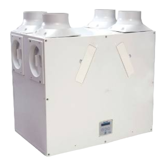
Page 3: Product Description
Sentinel Kinetic Summer By Pass Models. The Sentinel Kinetic B, BH, Plus B , Plus BS, S BH, BS and Plus CVP are fitted with a Summer By Pass (SBP) and will provide energy-free heating and energy-free cooling when the house temperature and ambient temperature allows. - Page 4 438222A - Sentinel Kinetic BS with summer bypass. 443319 - Sentinel Kinetic BH with summer bypass and integral humidity sensor. 443319A - Sentinel Kinetic S BH with summer bypass and integral humidity sensor 438342 - Sentinel Kinetic V without summer bypass. ...
-
Page 5: Control Unit Display
Product Description Control Unit Display The Control Unit is located at the front of the Sentinel Kinetic unit. The Control Unit provides the user interface for commissioning and monitoring purposes. Figure 2: Control Unit Display The main display is an LCD with automatic backlight,... - Page 6 Operating Humidity 0% to 95% RH Storage Temperature -20C to +45C Storage Humidity 0% to 95% RH Software Version For all other technical details, please see the Product Catalogue or our website at www.vent-axia.com. Sentinel Kinetic MVHR Operation & Monitoring...
-
Page 7: Powering Up The Unit
To switch the unit off: at the unit’s local isolator, turn the power off. Startup Screens Sentinel Kinetic Version Screen The Sentinel Kinetic Version screen displays the firmware version number for 3 seconds. No adjustments are possible on this screen. -
Page 8: Operation And Monitoring
Operation and Monitoring Overview When the Sentinel Kinetic unit has been installed and commissioned it should require no further intervention in order to operate, unless external switches are used to control on/off/boost, etc, or BMS control requires user action. Start-up Screens... -
Page 9: User Menu Screens
The normal screen top line will include Check Filter as a reminder to check and, if necessary, clean or replace the filters. When this has been done, press and hold the buttons for 5 seconds to reset the automatic message. Sentinel Kinetic MVHR Operation & Monitoring... - Page 10 Centigrade – only displayed when the bypass is fitted. Selectable range is 16-40 (25 default). Return to the normal display by pressing the button or leave to timeout and return automatically after 2 minutes. Sentinel Kinetic MVHR Operation & Monitoring...
-
Page 11: Boost & Purge Screens
‘take over’ the boost. Flow will return to low / normal when that device switches off. If a number of different devices are calling for boost flow, the unit will run at boost until the last one has reverted to normal. Sentinel Kinetic MVHR Operation & Monitoring... -
Page 12: Status Message Screens
Dryout Mode Screen The Dryout Mode screen displays the time remaining Dryout Mode for the building to dry out. The unit runs at maximum 168 h flow for 1 week. Sentinel Kinetic MVHR Operation & Monitoring... - Page 13 A Fan Off command could be received from the BMS in the event of a fire alarm. CV Failure The Fault Code screen is displayed when the Constant CV Control Volume stops working. Switched Off Sentinel Kinetic MVHR Operation & Monitoring...
-
Page 14: Maintenance
2. Remove front cover from the unit. 3. Remove the 2 filters. 4. Slide out the heat exchanger. For Sentinel Kinetic Plus CVP refer to pages 15 and 16. 5. Wash the outer cover and heat exchanger in warm water using a mild detergent (such as Milton Fluid) and dry thoroughly. -
Page 15: Heat Exchanger Removal Instruction For Cvp Unit
3. Pull out the Heat Exchanger Cell to gain access to the 2 screws on the cell as shown opposite. Loosen up the both screws (no need to remove them completely) to be able to remove the pressure tube and its rubber grommet strip. Sentinel Kinetic MVHR Operation & Monitoring... - Page 16 4 to 1. Do not over tighten the screws for securing clips. The clips should just slightly grip the rubber grommet strips as over tightening of the clips can block the air pressure. Sentinel Kinetic MVHR Operation & Monitoring...
-
Page 17: Troubleshooting
Table 2: Fault Codes Code Problem Supply Fan not running Extract Fan not running Control PCB 24 V fuse (FS1) failure Temperature sensor T1 (supply) faulty Temperature sensor T2 (extract) faulty Wired Remote Control failure Sentinel Kinetic MVHR Operation & Monitoring... -
Page 18: Appendix One: Control Mode 02 Description
Appendix One Appendix One: Control Mode 02 Description Overview The functional differences described in this Appendix are available when Control Mode 02 is selected from the start-up screens. Control Mode 02 assigns alternative functions to certain wiring Terminal Connections (described in Appendix One of the Installation and Commissioning Manual) and allows additional airflow settings to be accessed via the button on the front of the Kinetic unit or remote control as shown below: Airflow Mode Selection... - Page 20 Applicable only to products installed and used in the United Kingdom. For details of guarantee outside the United Kingdom contact your local supplier. Vent-Axia guarantees its products for two years from date of purchase against faulty material or workmanship. In the event of any part being found to be defective, the product will be repaired, or at the Company’s option replaced, without charge, provided that the product:-...
Need help?
Do you have a question about the Sentinel Kinetic and is the answer not in the manual?
Questions and answers