Table of Contents
Advertisement
Available languages
Available languages
Quick Links
Betriebsanleitung
Übersetzung der Original-Betriebsanleitung
Typ 0727
07271 - 07274
D r u c k l u f t g e r ä t
Düko Vertriebs-GmbH
Lülsdorfer Straße 32
53842 Troisdorf
Telefon: 02241/2520150
Fax: 02241/25201511
E-Mail: info@dueko.com
Internet: www.dueko.com
Hr.-Nr.: 16390
Ust.-IdNr.: DE 122652573
Geschäftsführer: O. Düren
F. Düren
Advertisement
Chapters
Table of Contents

Related Manuals for Avdel 0727


Summary of Contents for Avdel 0727
- Page 1 Betriebsanleitung Übersetzung der Original-Betriebsanleitung Typ 0727 07271 - 07274 D r u c k l u f t g e r ä t Düko Vertriebs-GmbH Telefon: 02241/2520150 Hr.-Nr.: 16390 Lülsdorfer Straße 32 Fax: 02241/25201511 Ust.-IdNr.: DE 122652573 53842 Troisdorf E-Mail: info@dueko.com Geschäftsführer: O.
- Page 2 Der Geschäftsgrundsatz von AVDEL ist die fortlaufende Weiterentwicklung. Die in diesem Dokument angegebenen technischen Daten sind Änderungen unterworfen, die nach Veröffentlichung eingeführt werden können. Für die neuesten Informationen stets Avdel zu Rate ziehen. T E C H N I S C H E D A T E N F Ü R G E R Ä T...
-
Page 3: Table Of Contents
S I C H E R H E I T S V O R S C H R I F T E N Allgemeines Spezifisch für Gerät 0727 A R B E I T S B E R E I C H Geräteleistungsvermögen... - Page 4 Wartung des Gerätes beauftragte Mitarbeiter die nachstehenden Sicherheitshinweise besondere Aufmerksamkeit schenken. NICHT ZWECKENTFREMDET VERWENDEN. MIT DIESEM GERÄT KEINE ANDEREN ALS DIE VON AVDEL EMPFOHLENEN UND GELIEFERTEN AUSRÜSTUNGEN VERWENDEN. FÜR JEDE VOM KUNDEN DURCHGEFÜHRTE ÄNDERUNG AN GERÄT/MASCHINE, MUNDSTÜCKEN, ZUBEHÖR UND ANDEREN VON AVDEL ODER IHREN VERTRETERN GELIEFERTEN EINZELTEILEN IST DER KUNDE ALLEINE VERANTWORTLICH.
- Page 5 WERDEN, BEVOR EIN ÜBERMÄSSIGER VERSCHLEISS AUFTRITT SOWIE STETS VOR ERREICHEN DER HÖCHSTZULÄSSIGEN ANZAHL VON NIETUNGEN. SETZEN SIE SICH BITTE MIT IHREM AVDEL-VERTRETER IN VERBINDUNG, DER IHNEN DEN WERT BEKANNTGEBEN WIRD, NACHDEM ER DIE SETZKRAFT IHRER ANWENDUNG MIT UNSEREM PRÜFGERÄT ZUR SETZKRAFTMESSUNG GEMESSEN HAT.
- Page 6 R B E I T S B E R E I C H Das Druckluftgerät 0727 wurde für das Setzen von Avdel-Magazin-Nieten (ausgenommen 1/16" Avlug) konstruiert. Es eignet sich deshalb ideal bei der Serien- oder Fließmontage für die verschiedensten Einsatzzwecke in allen Industriezweigen.
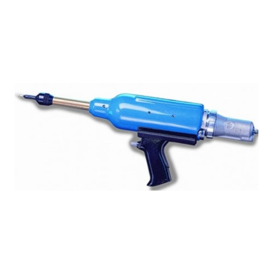
- Page 7 MODELLE 07271 und 07274 Diese sind Handgeräte, die sich vertikal an einem auf der Rückseite des Gerätes befestigten Ring aufhängen lassen. Während Modell 07274 mit nur zwei Kolben eine geringere Leistung hat (siehe Unterschiede in der Zeichnung der Grundgeräte auf Seite 25), bietet der weiter hinausragende Lauf bessere Zugangsmöglichkeiten.
- Page 8 N B E T R I E B N A H M E D R U C K L U F T V E R S O R G U N G MODELLE 07271 UND 07274 Alle Geräte sind druckluftbetätigt. Der optimale Druck beträgt 5,5 bar. Wir empfehlen die Verwendung von Druckreglern sowie automatischen Öl-/Filtersystemen für den Anschluß...
-
Page 9: Dämpfer
D Ä M P F E R W I C H T I G Durch den Einbau von Dämpfern wird der Hub des Gerätes gemindert; dies verkürzt die Taktzeit und nimmt Stoßbelastungen auf. Durch diese Minderung der Stoßbelastungen wird die Leistungsfähigkeit des Gerätes erhöht und die Standzeit des Nietdorns verlängert. -
Page 10: Laden Des Gerätes
Um die Rücklaufsperre umzukehren, wie folgt vorgehen: Die fettgedruckten Positionsnummer beziehen sich auf die Zeichnung RÜCKLAUFSPERRE der Grundgeräte und Ersatzteilliste auf Seite 25 und 26. ■ FEDERBEAUFSCHLAGTES Spannbackengruppe 1 ausbauen. ENDE ■ Nietdornführung 17 herausziehen. LAUF ■ Einen Nietdorn mit der Spitze voraus durch das hintere Ende des Laufs 59 einsetzen und eindrücken, bis er vorne am Luft 59 MUNDSTÜCK erscheint. - Page 11 MANDREL FOLLOWER SPRINGS IDENTIFICATION AND ORIENTATION FASTENER MANDREL/MANDREL FOLLOWER SPRING NOSE JAW MANDREL AND FASTENER ASSEMBLY SIZE NAME SIZE (SEE NOSE EQUIPMENT SECTION) MANDREL FOLLOWER SPRING MANDREL HEAD MANDREL FERRULE 3 /32" STANDARD TAPERED SPRING LIMITED ACCESS & 3 /32" BRIV LIMITED ACCESS CAM OPERATED 1 /8"...
-
Page 12: Nachladen Des Gerätes
1.5mm - 3mm 1 /16 1 /8 " - ") N A C H L A D E N D E S G E R Ä T E S ■ Spannbacken 9 des Gerätes öffnen. ■ Mundstück öffnen. Den leeren Nietdorn und die Nietdornfeder aus dem Gerät ziehen. ■... - Page 13 U S R Ü S T U N G Auf Schnellnietgeräten wie Modell 0727 besteht die Ausrüstung stets aus drei Bauteilen: einem Mundstück, einem Nietdorn und einer Nietdornfeder. Diese drei Teile müssen zum gesetzten Niet und zum Lochdurchmesser passen. W I C H T I G Um ein vollständiges Zerlegen des Gerätes zu vermeiden, ist es notwendig, die Orientierung der Rücklaufsperre vor Einbau...
- Page 14 AUSWAHL EINES MUNDSTÜCKS STANDARD ■ Bezeichnung, Größe und Werkstoff des zu setzenden Niets auflisten. ■ Für dieses Niet auf die erste Spalte der Mundstück-Auswahltabellen auf Seite 13 (für 28,6 Zollabmessungen) oder Seite 14 (für metrische Abmessungen) gehen. 1,125 ■ In der Tabelle nach rechts gehen und die zur Verfügung stehenden Mundstücke 33,5 notieren.
-
Page 15: Wahl Des Mundstücks
AUSWAHL DES MUNDSTÜCKS ZOLLMASS Die Spalte "BEZ.-NR." verweist auf die Spalte "BEZ.-NR." im Abschnitt über Nietdorne. Sie kennzeichnet den für ein besonderes Mundstück mit einem spezifischen Niet erforderlichen Nietdorn sowie die Nietdornfeder. MUNDSTÜCK MUNDSTÜCK BEZ. BEZ. BLINDNIET TYP UND FORM MASSE TYP UND FORM MASSE... - Page 16 AUSWAHL DES MUNDSTÜCKS METRISCHE MASSE MUNDSTÜCK MUNDSTÜCK BEZ. BEZ. BLINDNIET MASSE MASSE TYP UND FORM TYP UND FORM -NR. -NR. TEILNR. TEILNR. DES ENDSTÜCKS DES ENDSTÜCKS STANDARD - FLACH 07150-03003 9,14 33,02 4,06 # STANDARD - UNIVERSAL 07150-03203 9,14 33,78 6,10 STD NOCKENBETÄTIGT - FLACH 07170-04500...
- Page 17 übermäßiger Verschleiß auftritt sowie stets vor Erreichen der höchstzulässigen Anzahl von Nietungen. Setzen Sie sich bitte mit Ihrem Avdel-Vertreter in Verbindung, der Ihnen den Wert bekanntgeben wird, nachdem er die Setzkraft Ihrer Anwendung mit unserem prüfgerät zur setzkraftmessung gemessen hat. Dieses Gerät kann auch unter der Teilnummer 07900-09080 mit allen für das Prüfen erforderlichen Informationen angekauft werden.
- Page 18 Die unten links und rechts sowie auf den nächsten vier Seiten abgedruckten Tabellen enthalten eine Auflistung der Teilnummern für alle Nietdorne und Nietdornfedern pro Niet oder Nietengruppe, z.B. für Chobert und Grovit auf diesen Seiten. Während die Nietgrößen stets in den ihnen zugeordneten Maßeinheiten erscheinen, wurde jede Tabelle zweimal abgedruckt. Auf der linken Seite sind Zollmaße und auf der rechten Seite metrische Maße angegeben.
- Page 19 Um die korrekte Teilnummer eines Nietdorns für eine besondere Anwendung aufzufinden, die nachstehenden Anweisungen lesen, nachdem die Angaben entsprechend dem nebenstehenden Beispiel festgestellt wurden. Die Antworten für das Beispiel sind in grauer Kursivschrift gedruckt. NIETBEZEICHNUNG Beispiel Chobert NIETGRÖSSE 1/8" KATALOG Baureihe 1125 WERKSTÜCKLOCHDURCHMESSER 0,1335"...
- Page 20 KURZKONUS CHOBERT, GROVIT, (NUR CHOBERT AVSERT, AVTRONIC & GROVIT) BRIV BRIV (ROSTFREIER STAHL) RIVSCREW AVLUG Nietdornkopfarten und Länge "P". Nietdorne für Briv aus rostfreiem Stahl sind leicht durch einen V-Einschnitt im Ende der Nietdornköpfe erkenntlich. Bei Verwendung von gebogenen Mundstücken müssen die Nietdorne durch Biegen von Hand der Biegung des Mundstücks angepaßt werden, um eine gute Nietzuführung zu gewährleisten.
- Page 21 AVLUG, AVSERT, AVTRONIC & RIVSCREW ZOLLMASS Für die Auswahl von Nietdorn oder Nietdornfeder die Anweisungen auf Seite 15 befolgen. STANDARD-NIETDORN - GRÜN NIETDORN FÜR 1. ÜBERMASS - GELB BEZ.- LOCH- LOCH- FEDER- BLINDNIET KOPF NIETDORN- KOPF NIETDORN- Ø Ø TEILNR. -Ø...
- Page 22 AVLUG, AVSERT, AVTRONIC & RIVSCREW METRISCHE MASSE STANDARD-NIETDORN - GRÜN NIETDORN FÜR 1. ÜBERMASS - GELB BEZ.- LOCH- LOCH- FEDER- BLINDNIET KOPF NIETDORN- KOPF NIETDORN- Ø Ø TEILNR. -Ø TEILNR. MAX. -Ø TEILNR. MAX. WIE EMPF. 1,93 07150-06603 8,97 +,10 2,06 07150-06703 12,14...
- Page 23 A R T U N G D E S G E R Ä T E S Die Wartung ist in regelmäßigen Zeitabständen durchzuführen. Eine umfangreiche Prüfung ist jährlich oder alle 500 000 Arbeitstakte durchzuführen, je nachdem, was früher eintritt. W I C H T I G Der Arbeitgeber trägt die Verantwortung, sicherzustellen, daß...
- Page 24 Der Klebstoff sollte unter dem Kopf der Halteschraube 44 auf eine Länge von etwa 3,2 mm über das Gewinde aufgetragen werden. ■ Stets eine neue selbstklebende Griffpolsterung 57 einbauen. ■ Der Zusammenbau erfolgt in umgekehrter Reihenfolge. * Verweist auf die im Avdel-Werkzeugsatz enthaltenen Teile. Für eine vollständige Liste siehe oben.
- Page 25 Zum Ausbau Kolben 54 vorsichtig abdrücken. Spindel 52 herausziehen. ■ Reinigen und Dichtringe auf Verschleiß oder Schaden prüfen. ■ Ventilbohrung mit Molylithiumfett EP 3753 einschmieren. ■ Der Zusammenbau erfolgt in umgekehrter Reihenfolge. * Verweist auf die im Avdel-Werkzeugsatz enthaltenen Teile. Für eine vollständige Liste siehe Seite 22.
- Page 26 Rücklaufsperre reinigen und einölen. Beim Einbau vorne in den Lauf 59 auf korrekte Lage achten. Bei falschem Einbau den auf Seite 7 beschriebenen Vorgang befolgen. W I C H T I G Überprüfen Sie das Gerät. * Verweist auf die im Avdel-Werkzeugsatz enthaltenen Teile. Für eine vollständige Liste siehe Seite 22.
- Page 29 E S E I T I G E N V O N S T Ö R U N G E N ABHILFE STÖRUNG MÖGLICHE URSACHE ➝ Luftdruck erhöhen. ➝ Ungenügender Luftdruck. Das Gerät setzt kein ➝ Gerät am Druckluftanschluß schmieren. ➝...
- Page 31 Gut konstruierte Befestigungs- und Montagesysteme Übereinstimmungserklärung Wir, Avdel UK Limited, Watchmead Industrial Estate, Welwyn Garden City, Herts, AL7 1LY. Großbritannien erklären unter unserer alleinigen Verantwortung, daß das Produkt Typ 0727 Fabriknr..........auf welches diese Erklärung bezogen ist, mit den nachstehenden Normen oder anderen Entwicklungsdokumenten übereinstimmt:...
- Page 32 Besitzer sein. Alle Angaben dieser Unterlage sind unverbindlich und dienen nur zur Information. Unsere Produkte werden ständig weiterentwickelt und verbessert. Daher unterliegen die hier angegebenen Informationen grundsätzlich dem Ausschluss jeglicher Gewähr und dem Vorbehalt der jederzeit unbeschränkten Änderung ohne vorherige Ankündigung. Ihr lokaler Avdel Repräsentant steht Ihnen für neueste Informationen zur Verfügung.
- Page 33 Instruction Manual Original Instruction Type 0727 07271 - 07274 P n e u m a t i c P o w e r T o o l...
- Page 34 AVDEL policy is one of continuous development. Specifications shown in this document may be subject to changes which may be introduced after publication. For the latest information always consult Avdel. S P E C I F I C A T I O N S F O R 0 7 2 7 T Y P E T O O L ■...
- Page 35 O N T E N T S S A F E T Y General Specific to 0727 Tool I N T E N T O F U S E Tool Capability Tool Dimensions P U T T I N G I N T O S E R V I C E...
- Page 36 RECOMMENDED AND SUPPLIED BY AVDEL. ANY MODIFICATION UNDERTAKEN BY THE CUSTOMER TO THE TOOL/MACHINE, NOSE ASSEMBLIES, ACCESSORIES OR ANY EQUIPMENT SUPPLIED BY AVDEL OR THEIR REPRESENTATIVES, SHALL BE THE CUSTOMER'S ENTIRE RESPONSIBILITY. AVDEL WILL BE PLEASED TO ADVISE UPON ANY PROPOSED MODIFICATION.
- Page 37 ARE SHARP EDGES OR CORNERS ON THE APPLICATION. THE OPERATING PRESSURE SHALL NOT EXCEED 8 BAR - 120 LBF/IN BENCH MOUNTED TOOLS MUST NOT BE USED WITHOUT AN AVDEL GUARD AND WITH THE SHIELD IN POSITION ABOVE THE TOOL BARREL AND THEY SHOULD NOT BE OPERATED IF THE GUARD IS DAMAGED IN ANY WAY.
- Page 38 N T E N T O F U S E The pneumatic 0727 type tool is designed to place Avdel repetition fasteners (except ” Avlug) making it ideal for batch or flow- line assembly in a wide variety of applications throughout all industries.
- Page 39 07271 AND 07274 MODELS These are hand held models which can be suspended vertically from a ring mounted at the rear of the tool. While the 07274 is less powerful with only two pistons, (see differences on the general assembly, page 25), it gives greater access with its longer barrel protusion.
-
Page 40: Air Supply
U T T I N G I N T O S E R V I C E A I R S U P P L Y 07271 AND 07274 MODELS All tools are operated with compressed air at an optimum pressure of 5.5 bar. We recommend the use of pressure regulators and automatic oiling/filtering systems on the main air supply. -
Page 41: Bush Stops
B U S H S T O P S I M P O R T A N T Bush stops are fitted to reduce the stroke length of the tool thus the tool cycle time and shock loads. Minimising shock loads will increase the efficiency of the tool and will prolong the life of the mandrel. -
Page 42: Loading The Tool
To reverse the orientation of the cursor, follow these steps: Item numbers in bold refer to the general assembly and parts list CURSOR on pages 25 and 26. SPRING ■ LOADED END Remove tail jaw assembly 1. ■ Pull out mandrel guide 17. TOOL BARREL ■... - Page 43 MANDREL FOLLOWER SPRINGS IDENTIFICATION AND ORIENTATION FASTENER MANDREL/MANDREL FOLLOWER SPRING NOSE JAW MANDREL AND FASTENER ASSEMBLY SIZE NAME SIZE (SEE NOSE EQUIPMENT SECTION) MANDREL FOLLOWER SPRING MANDREL HEAD MANDREL FERRULE 3 /32" STANDARD TAPERED SPRING LIMITED ACCESS & 3 /32" BRIV LIMITED ACCESS CAM OPERATED 1 /8"...
-
Page 44: Reloading The Tool
1.5mm - 3mm 1 /16 1 /8 " - ") R E L O A D I N G T H E T O O L ■ Open tail jaws 9 of tool. ■ Open the nose jaws and pull the empty mandrel and mandrel follower spring out of the tool. ■... - Page 45 O S E E Q U I P M E N T On speed riveting tools such as the 0727 type, the nose equipment always consists of three elements; a nose jaw, a mandrel and a follower spring. All three items are matched to the fastener being placed and to the hole size in the application.
- Page 46 SELECTING A NOSE JAW STANDARD ■ List the name, size and material of the fastener to be placed. ■ Look for this fastener in the first column of the nose jaw selection tables on page 13 28.6 if using imperial measurements and on page 14 if using metric units. 1.125 ■...
-
Page 47: Nose Jaw Selection
NOSE JAW SELECTION IMPERIAL The ‘REF Nº’ column cross references with the ‘REF Nº’ columns in the mandrel section. It identifies both the mandrel and mandrel follower spring required for a particular nose jaw with a specific fastener. NOSE JAW NOSE JAW REF. - Page 48 NOSE JAW SELECTION METRIC NOSE JAW NOSE JAW REF. REF. FASTENER TYPE AND DIMENSIONS TYPE AND DIMENSIONS Nº Nº PART Nº PART Nº END FORM END FORM STANDARD - FLAT 07150-03003 9.14 33.02 4.06 # STANDARD - UNIVERSAL 07150-03203 9.14 33.78 6.10 STD.
- Page 49 It is the customer’s responsibility to ensure that mandrels are replaced before any excessive levels of wear and always before the maximum recommended number of placings. Contact your Avdel representative who will let you know what that figure is by measuring the broach load of your application with our calibrated measuring tool. These tools can also be purchased under part number 07900-09080, supplied with all necessary information for testing.
- Page 50 Tables below left and right and over the next 4 pages list part numbers of all mandrels and mandrel follower springs available per fastener or group of fasteners, i.e. for Chobert and Grovit on these pages. While fastener sizes are always shown in their specified units, each table has been produced twice to offer dimensions in imperial units on the left-hand page then in metric units on the right-hand page.
- Page 51 To find the correct part number of a mandrel for a particular application, read the instructions below after you have gathered the following information as per example alongside. Answers for the example are shown in grey italic. FASTENER NAME example Chobert FASTENER SIZE 1/8”...
- Page 52 SHORT REACH CHOBERT, GROVIT, (CHOBERT & AVSERT, AVTRONIC GROVIT ONLY) BRIV BRIV (STAINLESS STEEL) RIVSCREW AVLUG Mandrel head types and ‘P’ length. Mandrels for stainless steel Briv are easily identifiable by a ‘V’ cut in the end of the mandrel heads. When using curved nose jaws, mandrels have to be bent by hand to match the curvature of the nose jaw, thus ensuring good feed of fasteners.
- Page 53 AVLUG, AVSERT, AVTRONIC & RIVSCREW IMPERIAL For mandrel or mandrel follower spring selection, follow instructions on page 15. STANDARD MANDREL - GREEN 1ST OVERSIZE MANDREL - YELLOW REF. HOLE HOLE SPRING FASTENER HEAD MANDREL HEAD MANDREL Nº SIZE SIZE PART Nº Ø...
- Page 54 AVLUG, AVSERT, AVTRONIC & RIVSCREW METRIC STANDARD MANDREL - GREEN 1ST OVERSIZE MANDREL - YELLOW LINE HOLE HOLE SPRING FASTENER HEAD MANDREL HEAD MANDREL Nº SIZE SIZE PART Nº Ø PART Nº MAX. Ø PART Nº MAX. AS REC. 1.93 07150-06603 8.97 +.10...
- Page 55 E R V I C I N G T H E T O O L Regular servicing should be carried out and a comprehensive inspection performed annually or every 500,000 cycles, whichever is sooner. I M P O R T A N T The employer is responsible for ensuring that tool maintenance instructions are given to the appropriate personnel.
- Page 56 44 for an approximate length of 3.2 mm ( ") along the screw thread. ■ Always fit a new self adhesive cushion 57. ■ Complete assembly in reverse order of dismantling. * refers to items included in the Avdel service kit. For complete list see above.
- Page 57 Clean and inspect ‘O’ rings for signs of wear or damage. ■ Lubricate bore of valve with Moly Lithium EP3753 grease. ■ Assemble in reverse order of dismantling. * refers to items included in the Avdel service kit. For complete list see page 22.
- Page 58 Clean and oil cursor 21 ensuring correct orientation when refitting into the front of barrel 59. If incorrectly fitted follow the procedure on page 7. I M P O R T A N T Check the tool against daily and weekly servicing. * refers to items included in the Avdel service kit. For complete list see page 22.
- Page 61 A U L T D I A G N O S I S SYMPTOM POSSIBLE CAUSE REMEDY ➝ Low air pressure. ➝ Increase air pressure. Tool will not place ➝ Lack of lubrication. ➝ Lubricate tool at air inlet point. fastener.
- Page 63 Product Engineering Manager - Automation Tools BS EN ISO 9001&2: 1994 K E Y M E M B E R © Avdel 1995 ™ ® Products mentioned and/or illustrated within this publication are subject to patent, design or copyright protection in many countries...
- Page 64 This document is for informational purposes only. Infastech makes no warranties, expressed or implied, in this document. Data shown is subject to change without prior notice as a result of continuous product development and improvement policy. Your local Avdel representative is at your disposal should you need to confirm latest information.
Need help?
Do you have a question about the 0727 and is the answer not in the manual?
Questions and answers