Table of Contents
Advertisement
Quick Links
Advertisement
Chapters
Table of Contents

Related Manuals for King-Meter KM5S-LCD


Summary of Contents for King-Meter KM5S-LCD
- Page 1 KING-METER USERS GUIDE KM5S –LCD...
-
Page 2: Table Of Contents
目录 关于用户手册 · · · · · · · · · · · · · · · · · · · · · · · · · · · · · · · · · · · · · · · · · · · · · · · · · · · · · · · · · · · · · · · · · · · · · · · · · · · · · · · · 1 外观尺寸... - Page 3 密码使能 · · · · · · · · · · · · · · · · · · · · · · · · · · · · · · · · · · · · · · · · · · · · · · · · · · · · · · · · · · · · · · · · · · · · · · 11 密码修改...
- Page 4 质量承诺与包修范围 · · · · · · · · · · · · · · · · · · · · · · · · · · · · · · · · · · · · · · · · · · · · · · · · · · · · · · · · · · · · · · · · · · 24 引线连接图...
-
Page 5: 关于用户手册
关于用户手册 尊敬的用户, 为了更好的操作您的电动车, 请在使用前仔 细阅读 KM5S 仪表的说明书。 我们将以最简洁的语言告诉您仪 表使用的每一个环节, 包括从硬件的安装、 设置到仪表的正常 使用。同时帮助您解决有可能出现的困惑与障碍。... -
Page 6: 外观尺寸
外观尺寸 主要材质及颜色 KM5S 产品采用 PC 材料。外壳的材料允许在-20℃到 60℃ 温度中正常使用,并且能保证良好的机械性能。 实物图及尺寸图(单位:mm)... -
Page 7: 功能概述及按钮定义
功能概述及按钮定义 功能概述 KM5S 为您提供了多种功能及显示, 以满足您的骑行需要。 KM5S 显示的内容有: ◆电量显示, ◆电机功率显示, ◆速度显示 (包括实时速度显示, 最大速度显示及平均速 度显示) , ◆里程显示(包括单次里程显示和总里程显示) , ◆单次骑行时间显示, ◆6Km/h 助力推行显示, ◆背光开启, ◆错误代码显示, ◆多项设置参数。如:轮径、限速、电池电量设定、多种 助力档位选择和助力参数设定、 开机密码设定、 控制器限流设 定等等。 ◆默认参数修复功能。 正常显示区域 KM5S 正常显示界面... -
Page 8: 按钮定义
按钮定义 KM5S 仪表上有三个按钮。 包括开机/模式键、 加键和减键。 在后续的说明中, 按键用文字“MODE”替代。 按键 用文字“UP”替代, 按键用文字“DOWN”替代。 用户注意事项 在使用过程中注意使用安全, 不要在通电情况下插拔仪表。 仪表尽量避免磕碰。 仪表使用贴膜为防水贴膜,请不要撕开,以免影响 仪表防水性能。 关于仪表的后台参数设置, 请不要随意更改, 否则无 法保证正常骑行。 当仪表不能正常使用时应尽快送修。... -
Page 9: 安装说明
安装说明 将仪表固定在车把上, 调整好合适的视角。 在电动自行车 断电的情况下, 将仪表的接插件与控制器对应的接插件对插即 可完成安装。 正常操作 开机/关机 长按 MODE 键后,仪表开始工作,并提供控制器工作电 源。在开机状态下,长按 MODE 键,可以关闭电动车电源。 在关机状态下, 仪表不再使用电池的电源, 仪表的漏电流小于 1uA。 如果超过 10 分钟不使用电动车,仪表会自动关机。 仪表显示界面 仪表开机后,仪表默认显示实时速度。短按 MODE 键切 换显示信息。以依次显示:实时速度(单位:Km/h)→本次 骑行的平均速度(单位:Km/h)→本次骑行的最高速度(单 位:Km/h)→累计里程(单位:Km)→单次里程(单位:Km) →单次骑行时间→实时速度。... -
Page 10: 助力推行
实时速度显示 平均速度显示 最大速度显示 单次骑行时间显示 单次里程显示 累计里程显示 助力推行 按住 DOWN 不放,2 秒钟后,电动车进入电助力推行状 态。电动车以每小时 6 公里的速度匀速行驶。屏幕显示 PUS。 助力推行显示界面 6Km/h 助力推行功能只能在使用者推行电动车时使 用,请勿在骑行状态使用。 开启背光 长按 UP 延时 2 秒钟,仪表背光开启,同时通知控制器开 前灯。当外部光线不足或者夜晚行车的时候,可以开启 LCD... -
Page 11: 助力档位选择
背光。再次长按 UP 延时 2 秒钟,可以关闭 LCD 背光。 开启背光显示界面 助力档位选择 短按 UP 或 DOWN 按键, 切换电动车助力档位, 改变电机 输出功率,仪表默认输出功率范围是 1—5 档,1 档是最低功 率,5 档是最高功率。仪表开机默认档位是 1 档。 挡位切换显示界面 电量显示 当电池电压高时五段 LCD 均亮,当电池欠压时电池外边 框以 1HZ 的频率闪烁, 表示电池已严重欠压, 需要马上充电。 电池欠压闪烁 电池电量显示... -
Page 12: 功率显示
功率显示 通过仪表可以知道电动车输出功率。 显示方式如下图所示。 电池输出功率显示界面 错误代码显示 当电动车电控系统出现故障时, 仪表将自动显示错误代码, 详细错误代码的定义参见附表 1。 错误代码显示界面 只有故障被排除时才能退出故障显示界面,出现故 障后电动车将不能继续行驶。... -
Page 13: 用户设置
用户设置 开机前准备 确保接插件对接牢靠,并打开电动车电源。 常规设置 长按 MODE 键即可开机。在开机状态下,同时按住 UP 和 DOWN 键 2 秒钟后,仪表进入常规设置状态。 单次里程清零和单次骑行时间 TC 代表单次里程清零,设置参数可选 N/Y。默认 N 表示 单次骑行里程不清零。屏幕下方提示 SET1,表示设置项 1。 通过 UP/DOWN 可选择 Y/N, Y 表示单次骑行里程需要清零。 N 表示单次骑行里程不需要清零。短按 MODE 确认,进入背 光亮度界面。 单次里程和单骑行时间是同时清零的。 单次里程设置界面... -
Page 14: 仪表密码设置
背光亮度 BL 代表背光。可设置参数 1、2、3,表示背光亮度,1 是最暗,2 是标准亮度,3 是最亮。仪表出厂的默认数值是 1。屏幕下方提示 SET2,表示设置项 2。 通过 UP、DOWN,可改变背光亮度参数。长按 MODE 确认,退出常规设置状态。 背光设置界面 仪表密码设置 同时按住 UP+DOWN 2 秒钟后抬起, 进入常规设置状态。 然后同时按住 UP+MODE 2 秒钟, 可进入开机密码设置状态。 屏幕下方提示“-P-”,代表密码。“2”表示仪表的第二个密 码。短按 MODE 移位,通过 UP/DOWN 加/减输入数值。4 位密码输入完后,短按 MODE 确认。密码正确则进入开机密 码使能设置界面, 否则停留在密码输入状态。 输入密码: 1234。 密码输入设置界面... -
Page 15: 使用参数设置
密码使能 通过 UP/DOWN 选择 Y/N,Y 表示需要开机密码,N 表示 不需要开机密码。 短按 MODE 确认, 进入仪表密码修改界面。 仪表出厂的默认是 N。 密码使能确认界面 密码修改 PSD 表示密码。短按 MODE 移位,通过 UP/DOWN 加/ 减输入数值。修改完后,长按 MODE 保存确认,退出设置界 面。 密码修改界面 使用参数设置 同时按住 UP+DOWN 2 秒钟后抬起, 进入常规设置状态。 然后同时按住 MODE+DOWN 2 秒钟,要求输入密码,方可 更改仪表参数。仪表出厂默认密码是:0512。... - Page 16 输入设置密码界面 短按 MODE 移位,通过 UP/DOWN 加/减输入数值。4 位密码输入完后,短按 MODE 确认。密码正确则进入轮径设 置界面,否则停留在密码输入状态。 轮径设置 LD 表示轮径。可设置值有:16、18、20、22、24、26、 700C,28。通过 UP 和 DOWN 选择车辆对应的轮径,以确保 仪表速度显示和里程显示的准确性。 仪表出厂默认轮径数值是 26inch。 轮径设置界面 限速设置 仪表出厂的最高骑行速度默认值是 25Km/h。更改此数值 可以设定电动车的最高骑行速度, 当电动超过设定值时, 控制 器会停止对电机的供电,以保护骑行者的安全行驶。...
-
Page 17: 个性化设置
LS 表示限速。最高速度设定值的可选择范围是 12Km/h 到 40Km/h 之间。可以通过 UP/DOWN 进行加/减设置。长按 MODE 确认,并退出设置状态。 限速设置密码界面 个性化设置 为了提高此款产品的个性化使用, 我们特别加入了此项设 置。 能够针对使用者的不同要求对其进行设置。 在此项设置中 包括仪表的电池电量设置,助力档位设置,限流设置,助力传 感器设置,速度传感器设置和系统设置。共六大项设置。详细 设置项参见附表 2。 个性化设置密码输入 同时按住 UP+DOWN 2 秒钟后抬起, 进入常规设置状态。 再次同时按住 UP+DOWN,则进入个性化设置状态。 屏幕下方提示“-P-”,代表密码。“3”表示仪表的第三个密 码。短按 MODE 移位,通过 UP/DOWN 加/减输入数值。4 位密码输入完后,短按 MODE 确认。密码正确,则进入仪表 设置项选择界面, 否则停留在密码输入状态。后台参数设置密 码为:2962。... -
Page 18: 电池电量设置
后台输入密码界面 通过 UP、DOWN 选择需要设置的内容,短按 MODE 进 入对应的设置界面。 设置选择界面 电池电量设置 VOL 代表电压。要求 1 到 5 段电压值逐个输入。以第一个 电量值为例:屏幕中“1”表示第一个电压, “31.5”为第一个 电量值。通过 UP/DOWN 进行加/减改变数值。短按 MODE 确认,并进入下一个电量值的设置。5 个电量值设置完成后长 按 MODE 确认,退回仪表设置项选择界面。 电池电量设置界面... -
Page 19: 助力参数设置
助力参数设置 助力档位选择 在助力档位选择中提供了 8 中模式: 0-3、 1-3、0-5、1-5、 0-7、 1-7、 0-9、 1-9。 通过 UP/DOWN 切换, 短按 MODE 确认, 进入对应的助力比例数值设置界面。 助力档位选择界面 0-3 或 1-3:PAS1 同时显示 ECO, PAS2 同时显示 TOUR, PAS3 同时显示 BOOST。 0-5 或 1-5:PAS1 同时显示 ECO, PAS2 同时显示 CITY, PAS3 同时显示 TOUR,PAS4 同时显 POWER, PAS5 同时显示... -
Page 20: 限流数值设置
助力比例数值设置 通过设置助力比例数值, 可以调整每档的速度大小。 以满 足不同骑行者的需求。 以一档为例, “45-55%”为一档助力比例范围, “50%”为 一档的默认值,是可设定数值。通过 UP/DOWN 进行加/减设 置。短按 MODE 确认,进入下一个助力比例设置。最多可以 设定 9 个。设置结束后,长按 MODE 确认,退回仪表设置项 选择界面。短按 MODE 确认,返回助力档位选择。详细参考 附表 4。 助力比例数值设置界面 限流数值设置 CUR 代表限流。限流可设置范围为 7.0-22.0A。通过 UP/DOWN 改变控制器最大电流值。长按 MODE 确认,退回 仪表设置项选择界面。仪表出厂默认值为 15A。 根据控制器的硬件不同,控制器有可能无法达到设定 的 22A。... -
Page 21: 助力传感器设置
限流数值设置界面 助力传感器设置 助力传感器方向设置 PAS 代表助力传感器,屏幕上面显示 run-F/b。run-F 代表 正向,run-b 代表反向。通过 UP/DOWN 切换,短按 MODE 确认,进入助力传感器灵敏度设置。仪表出厂默认值为正向。 助力传感器方向设置界面 助力传感器灵敏度设置 屏幕下面显示 PAS, 代表助力传感器, 屏幕上面显示 SCN, 代表助力传感器的灵敏度。设置范围为 2-9。其中 2 表示灵敏 度最高, 9 表示灵敏度最低。 通过 UP/DOWN 进行加/减设置, 短按 MODE 确认,并进入助力传感器磁钢数设置界面。仪表 出厂默认值为 2。... -
Page 22: 速度传感器设置
助力传感器灵敏度设置界面 助力传感器磁钢数设置 NUB 代表磁钢的数量。通过 UP/DOWN 可以选择助力传 感器磁钢数 6/12。长按 MODE 确认,退回仪表设置项选择界 面。短按 MODE 确认,返回助力传感器方向设置界面。仪表 出厂默认值为 12。 助力传感器磁钢数设置界面 速度传感器设置 SPS 代表速度传感器。可以根据电动车车轮上所装的磁头 数进行设置,设置范围 1-9。通过短按 UP/DOWN 实现修改。 长按 MODE 确认,退回仪表设置项选择界面。仪表出厂默认 值为 1。... -
Page 23: 转把功能设置
速度传感器磁钢选择界面 转把功能设置 转把 助力推行使能设置 HL 表示转把 6Km 助力推行,HL:N 表示转把没有 6Km 功 能,HL:Y 表示转把有 6Km 功能,即当转动转把的时候,仪表 进入 6Km 助力推行模式。通过 UP/DOWN 可以切换 Y/N。短 按 MODE 确认。若选择 N 则进入转把矢量使能设置界面。否 则返回仪表设置项选择界面。仪表出厂默认值为 N。 转把 6Km 助力推行设置界面 转把矢量使能设置 HND 表示转把。HF:Y 表示转把分档,HF:N 表示转把不 分档。如果选择转把分档,则表示在转动转把的时候,骑行速 度会随转把的旋转角度而改变。 如果选择转把不分档, 则表示 在转动转把的时候,骑行速度不会随转把的旋转角度而改变。... -
Page 24: 系统设置
通过 UP/DOWN 可以设置 Y/N。长按 MODE 确认,返 回仪表设置项选择界面。短按 MODE 确认,返回转把 6Km 助 力推行使能设置界面。 转把分档使能设置界面 系统设置 电量延时时间设置 DLY 代表电量延时时间。通过 UP/DOWN 可以选择电量 延时时间 3/6/12s。 ,短按 MODE 确认,并进入最大限速设置 界面。仪表出厂默认 3s。 电量延时时间选择界面 最大限速设置 MAX SPD 代表最大速度。通过 UP/DOWN 可以设置最大 限速, 设置范围 25-40 Km/h。 长按 MODE 确认, 并退出设置。 仪表出厂默认... -
Page 25: 退出设置
此设置参数式仪表厂家规定之上限值。 最大限制速度设置界面 退出设置 在设定状态下,短按 MODE(2 秒以内) ,是确认输入保 存当前设置。长时间按 MODE(2 秒以上) ,是确认保存当前 设置,并退出当前设置状态。长按 DOWN(2 秒以上),为取消 当前操作,退出设置,不保存当前设置数据。 在一分钟内没进行任何操作, 仪表自动退出设置状态。... -
Page 26: 恢复默认设置
恢复默认设置 DEF 代表恢复默认参数。同时按住 UP+MODE 2 秒钟以 上, 可进入恢复默认参数。 通过 UP、 DOWN 来切换 Y 或 N。 N 表示不需要恢复默认参数。 长按 MODE 确认。 如果选择 Y, 需要输入一个密码,才能恢复默认参数。 恢复默认设置界面 输入密码:0368。短按 MODE 移位,通过 UP/DOWN 加 /减输入数值。4 位密码输入完后,短按 MODE 确认。仪表显 示如下图所示,当仪表显示 DEF:00 时表示恢复默认成功,自 动退出。 在恢复默认中,电池电量值、总里程和单次里程是不 恢复的。开机密码也在恢复之列。 输入恢复密码界面 恢复开始... -
Page 27: 常见问题及解答
常见问题及解答 问:为什么不能开机? 答:检查电池是否打开电源或外漏引线是否断裂。 问:仪表显示故障代码应如何处理? 答:及时到维修电动车的维修点修理。 关于仪表条形码 仪表条形码分为两行。第一行:KM5S000001。KM5S 代表 产品名称,000001 为产品序列号。第二行:12 06 3 101801。 其中 1206 代表仪表出厂日期为 2012 年第 6 周, 3 代表仪表的 电压参数(2-24V,3-36V,4-48V),1 代表样品,01 代表仪表 硬件版本号,801 代表仪表软件版本号。... - Page 28 质量承诺与包修范围 一、保修信息: 1、凡属正常使用情况下由于产品本身质量问题引起的故 障,在保修期内本公司将负责给予有限保修。 2、产品的保修期自仪表出厂 24 个月内。 二、保外条款: 以下情况不属于保修范围 1、外壳被打开 2、接插件被破坏 3、仪表出厂后,外壳划伤或外壳破损 4、仪表引出线划伤或断裂 5、由于不可抗拒(如火灾、地震等)或自然灾害(如雷 击等)所造成的故障或损坏 6、产品超出保修期...
- Page 29 引线连接图 标配接插件线序 与控制器连接端 仪表出线端 对接线端 表:标配接插件线序表 标配线序 标配线颜色 功能 红色(VCC) 仪表电源线 蓝色(K) 控制器的电源控制线 黑色(GND) 仪表地线 绿色(RX) 仪表的数据接收线 黄色(TX) 仪表的数据发送线 注:部分产品的引线采用防水接插件,用户无法看到线束内 的引线颜色。...
- Page 30 版本变更 本仪表的使用说明书是天津嘉特机电技术有限公司通用 软件版本(V1.0 版本)的操作说明书。部分整车上使用的仪 表软件版本有可能与本说明书略有差异, 均以实际使用版本为 准。...
- Page 31 附表 1:错误代码定义表 错误代码 定义 电流异常 转把异常 电机缺相 电机霍尔信号异常 刹车异常 通讯异常 附表 2:密码速查表 序 屏幕显示 密码 说明 号 使用参数设置密码 0512 (固定) 出厂默认 开机密码密码(可 修改) 1234 后台参数设置密码 2962 (固定) 恢复设置密码(固 0368 定)...
- Page 32 附表 3:个性化设置对应表 序号 设置项 屏幕显示 设置内容 5 个电量值设置 电池电量设置 助力档位选择 助力档位设置 助力档位比例 限制电流大小 限流设置 助力传感器方向 助力传感器灵敏度 助力传感器设 置 助力传感器磁钢数 速度传感器设 速度传感器磁钢数 置 转把分档使能设置 转把功能 转把 6Km 助力推行使能设置...
- Page 33 续表 3: 序号 设置项 屏幕显示 设置内容 电量延时时间 系统设置 最大速度设置 附表 4:助力档位比例默认值表 档位 档 位选项 0-3/ 1-3 — — — — — — 0-5/ 1-5 — — — — 0-7/ 1-7 — — 0-9/ 1-9...
- Page 34 附表 5:显示符号定义速查表 序号 符号 含义 设置 密码 电量延时 恢复默认 单次里程和单次骑行时间 清零 背光 转把分档 转把 6Km 助力推行 限速 轮径 问号 反向 正向 是 否...
- Page 35 Contents About the User Manual · · · · · · · · · · · · · · · · · · · · · · · · · · · · · · · · · · · · · · · · · · · · · · · · · · · 1 Appearance and Size ·...
- Page 36 Power-on Password Modify · · · · · · · · · · · · · · · · · · · · · · · · · · · · · 12 Normal Parameter Setting · · · · · · · · · · · · · · · · · · · · · · · · · · · · · · · · · · · · · · 12 Wheel Diameter Setting ·...
- Page 37 Connection layout · · · · · · · · · · · · · · · · · · · · · · · · · · · · · · · · · · · · · · · · · · · · · · · · · · · · · · · · · · 27 Version changes ·...
-
Page 38: About The User Manual
About the User Manual Dear users, To ensure better performance of your e-bike, please read through the KM5S product introduction carefully before using it. We will use the most concise words to inform you of all the details (including hardware installation, setting and normal use of the display)when using our display. -
Page 39: Appearance And Size
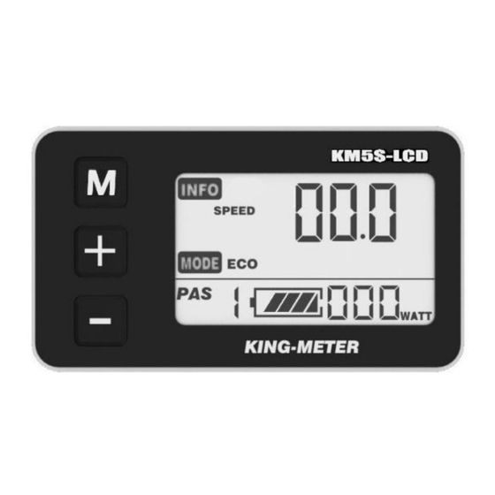
Appearance and Size Material and Color KM5S products are made of PC. Under the temperature of -20 to 60℃, the shell material can ensure normal usage and good mechanical performance. Real product and dimension figure (unit: mm) -
Page 40: Function Summary And Button Definition
Function Summary and Button Definition Function Summary KM5S provides a wide range of functions and indicators to fit the users’ needs. The indicated contents are as follow. ◆Battery Indicator ◆Motor Power Ratio ◆Speed Display (including running speed, max speed and average speed) ◆Trip Distance and total distance ◆Trip time ◆6Km/h Cruise control... -
Page 41: Button Definition
Button Definition KM5S has three buttons. They are .In the following introduction, is named as “MODE”. is named as “UP” and is named as “DOWN”. Operation Cautions Be cautions of safety use. Don’t attempt to release the connector when battery power on. Try to avoid hit. -
Page 42: Installation Instruction
Installation Instruction Fix the display onto the handlebar and adjust to an appropriate visual angle. Tighten all the connectors. Normal Operation Power On/Off Hold Mode button for 2 seconds display will power on, and display will power on the controller. With display on, hold MODE to turn off power supply of the e-bike. -
Page 43: Push Cruise Control
Running Speed Average Speed Max Speed Trip Time Trip Distance Total Distance Push Cruise Control Hold DOWN for 2 seconds to enter the mode of power assist walk. The e-bike will go on at a uniform speed of 6 Km/h. PUS showed on the screen. Push Cruise Control 6Km/h “Push Cruise Control”... -
Page 44: Turn On/Off Backlight
Turn on/off Backlight Hold UP 2 seconds to turn on the backlight of the display, the headlight will be power on at the same time. Hold UP for 2 seconds again, backlight turned off. Turn On/Off Backlight PAS Level Selection Hold UP or DOWN to change output power of the motor. -
Page 45: Motor Power Monitor
Low Voltage Flash Battery Indicator Motor Power Monitor Motor power showed as below: Error Code Information If there is something wrong with the electronic control system, error code appeared automatically. Detail information of error code in Table 1 attached. Error Code Make the display repaired when error code appears. -
Page 46: User Setting
User Setting Preparation before Starting Make sure all connectors tightened and cable without broken. General Setting Press MODE button to start the display, then hold both UP and DOWN for 2 seconds to enter setting menu. Trip Distance and Trip Time Clearance TC means trip distance clearance. -
Page 47: Backlight Contrast
Backlight Contrast BL means backlight. Level 1 is the low brightness. Level 2 is the middle brightness. Level 3 is high brightness. The default level is 2. Bottom of screen prompts SET2. Press UP or DOWN to modify the backlight brightness. Hold MODE to confirm the modification and exit the general setting. -
Page 48: Power-On Password Enable
MODE 2 seconds again enter power-on password enable/disable page. Press UP/DOWN to change the number .Press MODE to select digit one by one . After 4-digite of the correct password entered,MODE to confirm then select password enable or disable . Password Entering Page Power-on Password Enable Press UP/DOWN to select Y or N, MODE to confirm . -
Page 49: Power-On Password Modify
Power-on Password Modify UP and DOWN change the number, MODE to select digit one by one,hold MODE to confirm modification . Password Modify Page Normal Parameter Setting Hold both UP and DOWN for 2 seconds to enter User setting .And then hold both DOWN and MODE over 2 seconds to enter password 0512 to modify wheel size. -
Page 50: Speed-Limit Setting
Wheel Diameter Setting Page Speed-limit Setting When running speed over than MAX SPEED,controller will cut off the motor power.MAX SPEED default setting is 25Km/h .LS means Limit Speed 12Km/h to 40Km/h is selectable. Press UP/DOWN to select favorite value, hold MODE over 2 seconds to confirm and quit the setting mode . -
Page 51: Personalized Parameter Setting
Personalized Parameter Setting Personalized Parameter Setting can match variety requirements in use. Settings items are : Battery Power Bar Setting、Pedal assistant level Setting、Over-current Cut 、 Pedal Assistant Sensor Setting、Speed Sensor Setting and Delay Time Setting . For details, see Attached List 2. System Parameter Setting Hold UP and DOWN both over 2 seconds to enter normal setting , then hold UP and DOWN both again to... -
Page 52: Battery Power Bar Setting
Option Select Page Battery Power Bar Setting Each bar represents a voltage value. 5 value MUST BE entered one by one. MODE to confirm and UP/DOWN to Select the value . VOL = voltage Battery Power Bar Setting Pedal Assistant Level Setting Pedal Assistant Level Select In Pedal Assistant Level Setting , there have 8 modes to select :0-3、1-3、0-5、1-5、0-7、1-7、0-9、1-9 . - Page 53 UP/DOWN to select the mode , press MODE to confirm , then change the ratio of each PAS level . PAS Mode Select Page 0-3 or 1-3: PAS1 also shows ECO, PAS2 also shows TOUR, PAS3 also shows BOOST。 0-5 or 1-5: PAS1 also shows ECO, PAS2 also shows CITY, PAS3 also shows TOUR,PAS4 also shows POWER,...
-
Page 54: Pas Ratio Modify
PAS Ratio Modify Modify the value of PAS ratio to meet different requirments. The 1 level as example,“45-55” is the range value , bottom value could be modified, default is 50 . MODE to confirm and turn to next PAS ratio setting . After all PAS ratio inputted, hold MODE over 2 seconds to confirm the modification and turn to controller Over-current Cut setting (MODE back to pedal assistant level select page ). -
Page 55: Pedal Assistant Sensor Setting
CUR Setting Page Pedal Assistant Sensor Setting The Direction of Pedal Assistant Sensor Setting PAS means Pedal Assistant System. “run-F” means forward direction , “run-b” means back direction . UP/DOWN to select F or b, MODE to confirm and turn to PAS sensitivity setting . -
Page 56: Magnet Quantity Setting
The Sensitivity of PAS Setting Magnet Quantity Setting NUB means magnet numbers of PAS disk. UP/DOWN to select quantity 6 or 12 , hold MODE over 2 seconds to confirm selection and turn to Speed Sensor Selection . NUB default value is 12。 PAS Magnet Disk Selection Speed Sensor Selection SPS means Speed Sensor . -
Page 57: Throttle Defination
Speed Sensor Selection Throttle Defination Throttle Enable/Disable HL means throttle load,HL:N means 6Km function disable ,HL:Y means 6Km function enable . When HL=Y ,throttle can control the function of 6Km/h . UP/DOWN to select Y , MODE to confirm selection, otherwise select N to turn to Throttle Vector Enable Setting. -
Page 58: Systerm Setting
select Y or N , hold MODE to confirm selection and quit . MODE to confirm and turn to Throttle Defination page . Throttle Vector Enable/Disable Page Systerm Setting Delay time setting of battery power DLY means delay time of battery power. Choosing delay time 3/6/12s through pressing UP/DOWN, when short press MODE, setting the max speed limited. - Page 59 The standard speed limit setting is based on this setting, not more than this setting value. This setting is the priority version Interface of max speed limited setting Exit setting In the setting state, short press MENU (less than 2s) to input.
-
Page 60: Recover Default Setting
Recover default setting DEF means recover default. Meanwhile press UP+MODE to enter recover default setting. Pressing UP、 DOWN to convert Y or N.N means do not need to recover default setting; Y means entering into password setting. Otherwise, display will exit. The default state is N. Restore Default Setting Interface Input password: 0368. - Page 61 Start Complete Recover default interfac...
-
Page 62: Faq
Q: Why the display is not able to start up? A: Checking the connector between display and controller. Q: How to deal with the error code? A: Fix it to the maintenance place immediately . Barcode The barcode is build up as follows: KM5S=Name 000001=Sequence No. -
Page 63: Quality Assurance And Warranty Scope
Quality assurance and warranty scope Ⅰ、warranty 1、Any quality problems in normal case and in guarantee period, our company will responsible for the warranty. 2、The warranty time is 18 months when display out of the factory. Ⅱ、other items The following items are not belong to warranty scope 1、It can not be demolished. -
Page 64: Connection Layout
Connection layout Connector line sequence Display-side Connector Display-side adapter Switch wiring Line sequence table Line sequence Colour Function Red(VCC) Blue(K) Lock Black(GND) Green(RX) Yellow(TX) Some wire use the water-proof connector, users are not able to see the inside colou. -
Page 65: Version Changes
Version changes This operating instruction is a general-purpose version (V1.0). Some of the version of the display software will be different from the specification, all with actual use version. -
Page 66: Attached List 1:Error Code Definition
Attached list 1:Error code definition Error Code Definition Current Abnormality Throttle Abnormality Motor Abnormality Motor Hall Signal Abnormality Brake Abnormality Communication Abnormality Attached list 2: Password table Password Setting Using parameter setting 0512 password(settled) Default Starting up password 1234 Personality setting 2962 password(settled) Recovery setting... -
Page 67: Attached List 3:Personality Parameter Setting
Attached list 3:Personality Parameter setting Setting Display Details Five battery power value Battery power Power assist level option Assistance Assistance proportion Limit current Current-limiting PAS direction PAS sensitivity Power assist sensor PAS magnet No Speed sensor magnet No Speed sensor Throttle-changing Throttle Throttle 6km... -
Page 68: Attached List 4:Power Assist Table
Continue list 3: Items Display Setting Time of battery power delay System setting Max speed Attached list 4:Power assist table Level Level Item 0-3/ 1-3 — — — — — — 0-5/ 1-5 — — — — 0-7/ 1-7 — —... -
Page 69: Attached List 5:Symbol Definition
Attached list 5:symbol definition Symbol Definition Setting password Power delayed time Recover default Trip and time to clear backlight Throttle-changing Throttle 6Km power assist walk Speed limit Wheel diameter Question mark backward Forward... - Page 70 KING-METER...
Need help?
Do you have a question about the KM5S-LCD and is the answer not in the manual?
Questions and answers