Table of Contents
Advertisement
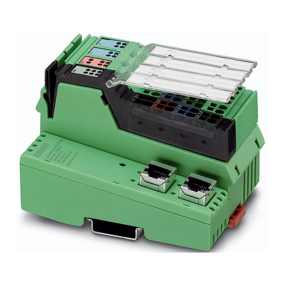
IL ETH BK DI8 DO4 2TX-PAC
Inline, bus coupler, Modbus/TCP (UDP),
digital inputs: 8, 24 V DC,
digital outputs: 4, 24 V DC, 500 mA
Data sheet
7275_en_09
1
Description
The bus coupler with integrated I/Os is intended for use
within a Modbus/TCP (UDP) network and represents the
link to the Inline I/O system.
Up to 61 Inline devices can be connected to the bus coupler.
The bus coupler supports a maximum of 16 PCP devices.
Features
–
2 Ethernet ports (with integrated switch)
–
Auto negotiation
–
Autocrossing
–
Transmission speed of 10 Mbps and 100 Mbps
–
Automatic detection of the transmission speed in the
local bus (500 kbps or 2 Mbps)
–
Eight digital inputs, four digital outputs (on-board)
–
Data exchange via OPC server supported
–
Software interfaces for access via TCP/IP: Device
Driver Interface (DDI) and High-Level Language
Fieldbus Interface (HFI)
–
Web-based management
WARNING: Explosion hazard when used in potentially explosive areas
When using the terminal in potentially explosive areas, observe the corresponding notes.
This data sheet is only valid in association with the IL SYS INST UM E user manual.
Make sure you always use the latest documentation.
It can be downloaded at:
© PHOENIX CONTACT
2020-02-26
phoenixcontact.net/product/2703981
Advertisement
Table of Contents

Related Manuals for Phoenix Contact IL ETH BK DI8 DO4 2TX-PAC

Summary of Contents for Phoenix Contact IL ETH BK DI8 DO4 2TX-PAC
-
Page 1: Description
IL ETH BK DI8 DO4 2TX-PAC Inline, bus coupler, Modbus/TCP (UDP), digital inputs: 8, 24 V DC, digital outputs: 4, 24 V DC, 500 mA Data sheet 7275_en_09 © PHOENIX CONTACT 2020-02-26 Description The bus coupler with integrated I/Os is intended for use within a Modbus/TCP (UDP) network and represents the... -
Page 2: Table Of Contents
IL ETH BK DI8 DO4 2TX-PAC Table of contents Description ..........................1 Table of contents ........................2 Ordering data .......................... 3 Technical data ......................... 5 Internal circuit diagram ......................9 Notes on using the terminal block in potentially explosive areas ........... 10 Safety note .......................... -
Page 3: Ordering Data
Type Order No. Pcs./Pkt. Inline, Bus coupler, Modbus/TCP(UDP), RJ45 socket, IL ETH BK DI8 DO4 2TX-PAC 2703981 digital inputs: 8, 24 V DC, connection method: 3-wire, digital outputs: 4, 24 V DC, 500 mA, connection method: 3-wire, transmission speed in the local bus: 500 kbps / 2 Mbps, degree of protection: IP20, including... - Page 4 IL ETH BK DI8 DO4 2TX-PAC Accessories Type Order No. Pcs./Pkt. Crimping pliers, for assembling the RJ45 plugs FL PLUG FL CRIMPTOOL 2744869 RJ45..., for assembly on site (Tools) Connector set, for Inline bus coupler with I/Os mounted in IL BKDIO-PLSET...
-
Page 5: Technical Data
IL ETH BK DI8 DO4 2TX-PAC Technical data Dimensions (nominal sizes in mm) 119,8 Width 80 mm Height 119.8 mm Depth 71.5 mm Note on dimensions Specfications with connectors General data Color green Weight 375 g (with connectors) Ambient temperature (operation) -25 °C ... - Page 6 IL ETH BK DI8 DO4 2TX-PAC Interface: Modbus/TCP (UDP) Number Connection method RJ45 socket Note on the connection method Auto negotiation and autocrossing Transmission speed 10/100 Mbps Transmission physics Ethernet in RJ45 twisted pair Interface: Inline local bus Connection method...
- Page 7 IL ETH BK DI8 DO4 2TX-PAC Segment circuit supply (U Supply voltage 24 V DC (via Inline connector) Supply voltage range 19.2 V DC ... 30 V DC (including all tolerances, including ripple) Power supply unit max. 8 A DC (Sum of U ;...
- Page 8 IL ETH BK DI8 DO4 2TX-PAC Digital outputs Maximum output current per device Nominal load, ohmic 12 W Nominal load, inductive 12 VA (1.2 H, 48 Ω) Nominal load, lamp 12 W Signal delay typ. 1.2 ms Maximum operating frequency with inductive nominal 0.5 Hz (1.2 H, 48 Ω)
-
Page 9: Internal Circuit Diagram
IL ETH BK DI8 DO4 2TX-PAC Internal circuit diagram µP Local bus DO1...4 DI1...8 ACT1/2 LNK1/2 8 x DI 7,5V 2 TX ETH Figure 1 Internal wiring of the terminal points Key: Power supply unit Microprocessor µP Electrically isolated area... -
Page 10: Notes On Using The Terminal Block In Potentially Explosive Areas
IL ETH BK DI8 DO4 2TX-PAC Notes on using the terminal block Safety note in potentially explosive areas NOTE: Risk of unauthorized network access WARNING: Explosion hazard Connecting devices to a network via Ethernet Please make sure that the following notes and entails the danger of unauthorized access to instructions are observed. -
Page 11: Connecting Ethernet, The Supply, Actuators, And Sensors
IL ETH BK DI8 DO4 2TX-PAC Connecting Ethernet, the supply, actuators, and sensors Connecting Ethernet Connect Ethernet to the bus coupler via an 8-pos. RJ45 connector. The Ethernet connections are set to autocrossing. Shielding The shielding ground of the connected twisted pair cables is electrically connected with the socket. -
Page 12: Connection Example
IL ETH BK DI8 DO4 2TX-PAC Connecting the supply, actuators, and sensors Terminal point assignment of the output connector (2) - terminal point assignment Terminal Assignment Terminal Assignment point point OUT1 OUT2 OUT3 OUT4 Terminal point assignment of the input connector (3) -
Page 13: Local Diagnostic And Status Indicators
IL ETH BK DI8 DO4 2TX-PAC Local diagnostic and status indicators BO RY P W R LNK1 ACT1 ACT2 LNK2 Figure 4 Local diagnostic and status indicators Designation Color Meaning State Description LNK 1/2 Green Link port 1/2 Connection via Ethernet to a module via port 1/2 established... - Page 14 IL ETH BK DI8 DO4 2TX-PAC Designation Color Meaning State Description O1: diagnostics of the Inline station/diagnostics and status of the outputs Green Diagnostics Data transmission active within the station Flashing Data transmission not active within the station Error Short circuit/overload at one of the outputs No short circuit/overload at one of the outputs 1 ...
-
Page 15: Reset Button
IL ETH BK DI8 DO4 2TX-PAC Reset button If you wish to restore the default settings, proceed as follows: The reset button is on the front of the bus coupler. • Disconnect the power to the module. The reset button has two functions: •... -
Page 16: Startup
IL ETH BK DI8 DO4 2TX-PAC Startup Startup behavior of the bus coupler The startup behavior of the bus coupler is determined by the 12.1 Starting the firmware following system parameters: By default, the bus coupler has no valid IP... - Page 17 IL ETH BK DI8 DO4 2TX-PAC Plug and Play mode inactive 13.3 Delayed startup (delayed start data transfer) When plug and play mode is deactivated, the reference Firmware version 1.42 or later. configuration is compared to the physical configuration. If...
- Page 18 IL ETH BK DI8 DO4 2TX-PAC 13.4 Possible combinations of modes Plug and Play Expert mode Description/effect mode Deactivated Deactivated Normal case. The station sets the valid configuration to the “RUN” state. The process data exchange is possible. Activated Deactivated The connected configuration is stored as the reference configuration and the station is set to the "RUN"...
-
Page 19: Monitoring
IL ETH BK DI8 DO4 2TX-PAC 13.6 Changing and starting a configuration in plug- Monitoring and-play mode Various functions are available for monitoring the Ethernet communication: Ensure that plug-and-play mode is enabled – Process data watchdog (process data monitoring) and expert mode is disabled. - Page 20 IL ETH BK DI8 DO4 2TX-PAC 14.2 Process data watchdog / process data Acknowledge error message monitoring To reset the error, it must be acknowledged. The following options are available: By default upon delivery, the process data – Web-based management watchdog is activated with a timeout of –...
-
Page 21: Modbus Protocols And Registers
IL ETH BK DI8 DO4 2TX-PAC The following causes are possible: Modbus protocols and registers Cause Code The bus coupler supports a Modbus/TCP server and a (hex) Modbus/UDP server. DDI_NF_TASK_ Error when starting 0001 The Modbus protocol can be used in both in a connection-... - Page 22 IL ETH BK DI8 DO4 2TX-PAC 15.5 Modbus register Modbus register table Access Function Access with function code (16-bit word) Local bus 1400 Number of local bus devices/entries FC3, FC4 1401 ... 1463 ID code and length code of the relevant device...
- Page 23 IL ETH BK DI8 DO4 2TX-PAC 15.6 Assignment of process data ETHERNET RESET LNK1 ACT1 LNK2 ACT2 MODBUS register/location of process data Address 8000 x x x x x x x x Address 8001 x x x x x x x x...
- Page 24 IL ETH BK DI8 DO4 2TX-PAC ETHERNET RESET LNK1 ACT1 LNK2 ACT2 Address 0000 Digital IN x x x x x x x x Address 0001 x x x x x x x x Address 0002 Address 0191 Address 0192...
- Page 25 IL ETH BK DI8 DO4 2TX-PAC 15.7 Diagnostic registers (7996 ... 7999) The diagnostic registers provide an overview of the general operating state of the bus coupler and the connected devices. In order to respond quickly in the event of an error, the error source and sometimes even the exact error location are specified.
- Page 26 IL ETH BK DI8 DO4 2TX-PAC READY, ACTIVE, RUN status displays Error with local bus shutdown The READY, ACTIVE, and RUN status displays show the Error bit Error location Contents of current state of the local bus system. the diagnostic The diagnostic parameter register is not used.
-
Page 27: Special Registers
IL ETH BK DI8 DO4 2TX-PAC Special registers 16.2 Register 1400 ... 1463: local bus configuration The bus coupler makes the local bus configuration available 16.1 Register 1280: Modbus connection timeout in these registers. A monitoring mechanism can be activated for every... - Page 28 IL ETH BK DI8 DO4 2TX-PAC 16.2.4 Register 2006: command register 16.2.7 Electronic rating plate (2075 ... 2089) You can use the network interface command register to Firmware version 1.42 or later. transmit commands with basic functions to the bus coupler The electronic rating plate contains the basic information on using the Ethernet host controller.
- Page 29 IL ETH BK DI8 DO4 2TX-PAC 16.3 Modbus/TCP PCP registers Communi- Communi- Configura- Note The PCP registers are divided into two classes: cation cation tion register – Communication registers for exchanging data with the reference register desired PCP device CR 2 6020 ...
- Page 30 IL ETH BK DI8 DO4 2TX-PAC 16.4 Transmitting an odd number of data bytes via Example 2: Reading 11 data bytes from the 5FE0 PCP (firmware version 1.30 or later) object of the PCP device with communication reference 4 (CR 4) The Modbus functions allow you to exchange data words with PCP devices.
-
Page 31: Ddi: Device Driver Interface
IL ETH BK DI8 DO4 2TX-PAC DDI: Device Driver Interface 17.4 Firmware services It does not make sense to use every firmware service in both The bus coupler supports access via the Device Driver operating modes (activating or deactivating expert mode). - Page 32 IL ETH BK DI8 DO4 2TX-PAC 17.4.1 Supported firmware services that can be used in every operating mode Code (hex) Service Function 0309 Read_Configuration Reads various entries of the configuration directory Used_Attributes: 0002 = Device code 030B Complete_Read_Configuration Reads all the device data for a configuration...
- Page 33 IL ETH BK DI8 DO4 2TX-PAC 17.4.3 System parameters for the Set_Value (0750 ) and Read_Value (0351 ) services Variable_ID (hex) System parameter Length Value/note 0104 Diagnostic status register 16-bit word Read only 0105 Diagnostic parameter register 1 16-bit word Read only 010D Diagnostic parameter register 2...
- Page 34 IL ETH BK DI8 DO4 2TX-PAC 17.5 PCP communication 17.5.3 Configuration of the PCP PDU size The standard PDU size for communication with all Inline 17.5.1 Transmission of parameter data devices is 64 bytes in the transmit and receive direction. Simple devices exchange process data. However, there are System couplers such as the ILC 200 UNI-PAC have...
-
Page 35: Hfi: High-Level Language Fieldbus Interface
IL ETH BK DI8 DO4 2TX-PAC HFI: High-Level Language Fieldbus Firmware update Interface In order to update the firmware of the bus coupler, provide the bus coupler with a firmware container via a TFTP server The bus coupler supports access via the High-level or load it onto the bus coupler via FTP. - Page 36 IL ETH BK DI8 DO4 2TX-PAC IP_ADDRESS In the event of an error in the Inline station, this is indicated in the diagnostic registers. The D LED on the bus coupler Contains the IP address of the station. flashes. The process data is invalid because only internal values are MODULE_NUMBER indicated, not the values on the local bus.
-
Page 37: Snmp: Simple Network Management Protocol
A message is displayed here informing you whether the last password change was successful. Result 1: Not known 2: Failed 3: Successful PHOENIX CONTACT GmbH & Co. KG • Flachsmarktstraße 8 • 32825 Blomberg • Germany 7275_en_09 37 / 37 phoenixcontact.com...
Need help?
Do you have a question about the IL ETH BK DI8 DO4 2TX-PAC and is the answer not in the manual?
Questions and answers