Table of Contents
Advertisement
Quick Links
Advertisement
Table of Contents

Summary of Contents for Inkema RH11
- Page 1 Loading Bays • Dock Shelters • High-Speed Doors Fire Doors • Free Standing Frames and Dock Houses • Scissor Lifts Loading Bridges • Industrial Doors Instructions manual Hydraulic dock leveller Models: RH11 and RH12 EMBEDDED AND SELF-SUPPORTING RH11 RH12 Contents...
-
Page 2: Table Of Contents
01 – Introduction............................3 02 – Technical specifications ........................4 02.01 – Usage conditions and limits ......................... 4 02.02 – RH11 embedded pit ..........................4 02.03 – RH12 self-supporting pit ........................5 02.04 – Platform ............................... 5 02.05 – Lip ................................ 5 02.06 –... -
Page 3: Introduction
Inkema 01 – Introduction This manual is a guide for the correct, safe installation, use and maintenance of the RH11 and RH12 dock levellers. Compliance with the instruction set forth herein ensures the long life of the machine and respect for the safety guidelines prevents the most common work or maintenance-related accidents. -
Page 4: Technical Specifications
Instructions manual RH11 and RH12 Inkema 02 – Technical specifications Ramp designed pursuant to the UNE-EN 1398 standard Calculated for a maximum nominal load of: (See its plate characteristics) 02.01 – Usage conditions and limits Nominal load capacity 6t ... -
Page 5: Rh12 Self-Supporting Pit
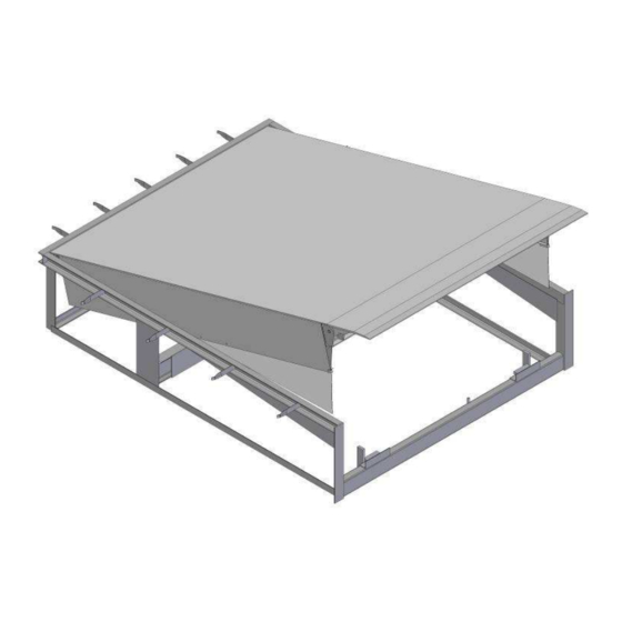
Instructions manual RH11 and RH12 Inkema 02.03 – RH12 self-supporting pit Recess tube Ø50mm. for electrical conductors as far as the electrical panel. Allow for guide cable inside the tube. Detail B Corrugated steel notches Ø20 embedded in concrete and Detail A laid out on either side. -
Page 6: Hydraulic Power Unit
Instructions manual RH11 and RH12 Inkema 02.07 – Hydraulic power unit 1.0CV electric motor. 0’75kw 230/400Volt 3F 50Hz. Hydraulic pump with flowrate of 5 litres/minute. 7-litre tank with oil level viewer. Logicblock where all the elements are incorporated (including 24V electro valve). -
Page 7: Hydraulic Unit Version 07
Instructions manual RH11 and RH12 Inkema 02.07.02 – Hydraulic unit version 07 02.08 – Electrical control panel (See electrical control panel connections, page 17) Transformer for manoeuvring circuit at 24Volt. AC. Green light indicating ON. Emergency stop/section switch. -
Page 8: Maintenance
The correct operation and long life of the ramp depend largely on the preventive maintenance work carried out. Advanced maintenance may only be carried out by the INKEMA technical service or staff authorised by the latter. This maintenance is carried out to ensure that the product conserves the safety and usage characteristics it had when it was first installed. -
Page 9: Maintenance Plan
Instructions manual RH11 and RH12 Inkema 02.10.05 – Maintenance plan Every Maintenance job Daily 6 months 1 year 2 years month General state of the machine Greasing Hydraulic oil level ... -
Page 10: During Use
Instructions manual RH11 and RH12 Inkema 02.11.02 – During use The dock leveller will merely rest on the load surface (truck). The hydraulic cylinders MUST NOT be blocked to allow the leveller to adapt to the height of the load surface (which will vary, depending on the variation in the truck suspension). -
Page 11: Ce Declaration
Instructions manual RH11 and RH12 Inkema 03 – CE Declaration DECLARATION OF CONFORMITY INKEMA SISTEMAS, S.L. declares, under its own responsibility, that the electro hydraulic dock levellers: Make : INKEMA Model : RH11 and RH12 with a capacity of 6000 Kg... -
Page 12: Machine Units And Parts
Instructions manual RH11 and RH12 Inkema 04 – Machine units and parts Pos. Part code Description 20.0002 … (*) 6t RH bedplate (*) 20.0001 … (*) 6t RH structure (*) 20.0003 … (*) 6t RH swing lip (*) 20.0017.0001 RH hydraulic power unit (Complete) 30.0015.0005... - Page 13 Instructions manual RH11 and RH12 Inkema 30.0008 …(*) Galv. mobile toe guard 30.0012.0002 M6x16 ISO-7380 zinced Allen truss head cap screw 30.0012.0003 M6 DIN-985 zinced self-locking nut 30.0006.0008 Zinqued axle Ø16 x 70 30.0012.0039 Ø5x28 DIN-94 Cotter Pin 20.0018.0001 RH electrical panel (standard) 30.0015.0104...
-
Page 14: Installation
Instructions manual RH11 and RH12 Inkema 05 – Installation 05.01 – Positioning in the pit VERY IMPORTANT: When handling the leveller, always respect the occupation risk prevention legislation and the regulations regarding safety, hygiene and health at work. Place it in the pit with the help of a crane, fork lift truck or similar element, using the worm screws, and chains, slings and similar items to lift it. -
Page 15: Securing In The Case Of A Self-Supporting Model
Instructions manual RH11 and RH12 Inkema The weld areas are indicated in the following diagram: 2 weld cords with a throat of 6mm. and length of 200mm. coinciding with the points where the lip is supported on the front of the machine. -
Page 16: Installing The Electrical Control Panel
Lastly, check the condition of the leveller paint, correcting any flaws (including the levelling plates). The installation is considered completed when the installer authorised by INKEMA has filled in the respective installation control sheet. V03 – 2016... -
Page 17: Electrical Control Panel Connection
Instructions manual RH11 and RH12 Inkema 05.05 – Electrical control panel connection Before installing the automatisms, check that the power supply is disconnected 05.05.01 – Connecting the power input 3-phase 380 V connection 3-phase 220 V connection MOTOR GUARD MOTOR GUARD... -
Page 18: Description Of The Connection Terminals
Instructions manual RH11 and RH12 Inkema 05.05.04 – Description of the connection terminals Ground Power input 220V ac Power input 220V ac Voltage 24V ac Electro valve output 24V ac Electro valve output 24V ac (24V ac power) FC2 N.C. electro valve limit switch Common Limit Switches FC1 N.C. -
Page 19: Actions Selection
Instructions manual RH11 and RH12 Inkema 05.05.05 – Actions Selection Select the type of operation using the micro switches. TABLE type Man present manual operation RH1 LEVELLER type semi-automatic operation BAY WITH AUTOMATIC RETURN type semi-automatic operation. 05.05.06 – Timers Leveller raising time. -
Page 20: Dismantling
Instructions manual RH11 and RH12 Inkema 06 – Dismantling 06.01 – Dismantling an embedded leveller VERY IMPORTANT: When handling the leveller, always respect the occupation risk prevention legislation and the regulations regarding safety, hygiene and health at work. To dismantle the leveller, it must be in the rest position. - Page 21 Instructions manual RH11 and RH12 Inkema As an additional safety measure, a sling will be placed on the platform as follows: At the ends of the lip axle (1) to embrace the back part (2). Use chains, slings or similar elements (with a load capacity equal to or greater than the weight of the leveller and keep under voltage, ensuring that the platform is not raised, so as not to block the maintenance lever.
-
Page 22: Incidents
Instructions manual RH11 and RH12 Inkema 07 – Incidents Warning: All checks must be made taking the opportune safety measures: - Do not perform checks when under voltage. - Ensure which voltage is being measured with the multimeter. - All cable connections and disconnections will be made when not under voltage. -
Page 23: The Ramp Does Not Rise
Instructions manual RH11 and RH12 Inkema 07.02 – The ramp DOES NOT rise Check the voltage between panel L1, L2 and L3 - There should be 400v between L1 and L2 - There should be 400v between L1 and L3 - There should be 400v between L2 and L3 ... -
Page 24: The Leveller Does Not Descend
Instructions manual RH11 and RH12 Inkema 07.03 – The leveller DOES NOT descend Check that PIN 1 is at ON - (When functioning as a table PIN 1 must be at OFF) Check the safety device FC2 in terminals 7 and 8... -
Page 25: Contact
Instructions manual RH11 and RH12 Inkema 08 – Contact Inkema Sistemas S.L Branches in Spain: C/ Galileo, 2 – Naves 7 y 8 Tel: +34 93 544 47 08 Apartado de correos 132 Fax: +34 93 572 30 11 08150 Parets del Vallés inkema@inkema.com...
Need help?
Do you have a question about the RH11 and is the answer not in the manual?
Questions and answers