Table of Contents
Advertisement
Quick Links
Owner and Installation Manual
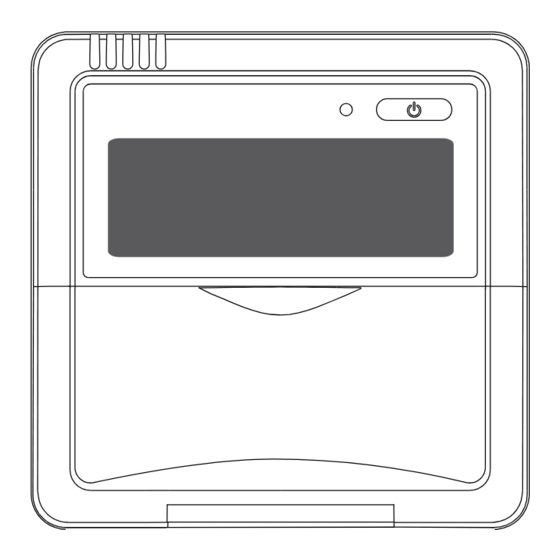
DURASTAR 12B Wired Thermostat
FOR DURASTAR SPLIT-STYLE INDOOR UNITS
Model Number:
Serial Number:
Purchase Date:
Installing Contractor Company Name:
TIP
Capture relevant information about your Durastar mini-split equipment before it is installed and
write it above for future reference.
©2023 Ferguson Enterprises, LLC V1.0_01.23
DURASTAR.COM
Advertisement
Table of Contents

Related Manuals for DURASTAR 12B

Summary of Contents for DURASTAR 12B
- Page 1 FOR DURASTAR SPLIT-STYLE INDOOR UNITS Model Number: Serial Number: Purchase Date: Installing Contractor Company Name: Capture relevant information about your Durastar mini-split equipment before it is installed and write it above for future reference. DURASTAR.COM ©2023 Ferguson Enterprises, LLC V1.0_01.23...
-
Page 2: Table Of Contents
• Read the troubleshooting section of this manual as it will help you diagnose and solve Field Supplied Installation Accessories ........6 common issues. Optional Accessories ................6 • Visit us on the web at www.durastar.com to download product guides and up-to- Tools Needed .................... 6 date information. Mounting The Thermostat ................7 Exposed Wire Mounting .............. -
Page 3: Compatability Chart
Included Parts And Accessories Compatability Chart This chart shows mini-split compatability with the the 12B wired thermostat. The following items are included in the kit: COMPATABILITY Number Name Quantity DRAW06F1B, DRAW09F1B, DRAW12F1B, DRAW18F1B, DRPDRAD09F1A17 Wall Mounted DRAW24F1B 12B Controller DRAW09F1A, DRAW12F1A,... -
Page 4: Field Supplied Installation Accessories
2. Remove the top panel of the thermostat by inserting a screwdriver into the two slots on the bottom. Slots WARNING • The Printed Circuit Board (PCB) is mounted in the upper panel of the thermostat. Be careful not to damage the board with the screwdriver. DURASTAR.COM DURASTAR.COM... -
Page 5: Embedded Wire Mounting
Fasten the back plate to a wall One M4 Screw with two M4 screw. Two M4x25 Screws Embedded Switch Box Wiring Wiring through Wall Wiring Hole Wall hole and wiring hole Diameter of wall hole Φ 2 cm DURASTAR.COM DURASTAR.COM... -
Page 6: Connecting The Thermostat
This thermostat is not compatible with the DRAC24F1B. NOTE • If there is a connection lug at the end of the shielded wire, the connection lug should be properly grounded. • Make sure to reserve a length of the lead wire for periodic maintenance. DURASTAR.COM DURASTAR.COM... -
Page 7: Wired Thermostat
Press to select the operating mode. → → → → Dry (Dehumidify) • Press the MODE button and select DRY. • Set your desired temperature using the TEMP down or TEMP up button. • Press the ON/OFF button to start the unit. DURASTAR.COM DURASTAR.COM... -
Page 8: Advanced Features
No buttons need to be pressed to set this feature - it is automatic. Current Time 2:00PM 3:00PM 3:30PM 4:00PM 5:00PM 6:00PM 1:00PM 2.5 hours later 5 hours later DURASTAR.COM DURASTAR.COM... -
Page 9: Led Display Indicators
The set temperature has been reached, at which point the unit turns off the 3. Press the MANUAL button again to activate FORCED COOLING mode. compressor. The unit will continue operating when the temperature fluctuates again. Display Manual Optional Display Control Panel Panel Button MANUAL buton DURASTAR.COM DURASTAR.COM... -
Page 10: Wiring Diagram
Wiring Diagram Wire Joint, 5p This page left blank intentionally Infrared Pipe 5-core Shield Cable Indoor Unit Switch Board Indoor Unit Dimensions 1/2" 13/16" (13mm) (21mm) 4-3/4"(120mm) 1-15/16" (50mm) DURASTAR.COM DURASTAR.COM ©2023 Ferguson Enterprises, LLC V1.0_01.23...
Need help?
Do you have a question about the 12B and is the answer not in the manual?
Questions and answers