Shure ADX5D - Portable Slot-In Receiver Manual
- User manual (45 pages) ,
- Manual (33 pages)
Advertisement
- 1 Features
- 2 Optional Accessories
- 3 Hardware Callouts
- 4 Hardware Setup
- 5 Scan for Available Frequencies
- 6 IR Sync
- 7 Home Screen
- 8 Icons
-
9
Menus and Configuration
- 9.1 Shortcut Menu
-
9.2
Device Configuration Menu
- 9.2.1 Device configuration menu map
- 9.2.2 Party Dial
- 9.2.3 3.5mm Cfg
- 9.2.4 Display
- 9.2.5 Advanced
- 9.2.6 Device Audio
- 9.2.7 Device RF
- 9.2.8 Device ID
- 9.2.9 ShowLink
- 9.2.10 Access Ctrl
- 9.2.11 Net Browse
- 9.2.12 HW Identify
- 9.2.13 Tx Fw Update
- 9.2.14 3rd Party Control
- 9.2.15 About
- 9.2.16 Factory Reset
- 9.2.17 User Presets
- 9.2.18 Menu Lock
- 9.2.19 Power Status
-
9.3
Channel Menu
- 9.3.1 Channel menu map
- 9.3.2 New Freq
- 9.3.3 Radio
- 9.3.4 Channel Scan
- 9.3.5 Group Scan
- 9.3.6 Channel Name
- 9.3.7 Sync
- 9.3.8 Advanced
- 9.3.9 Spectrum Scan
- 9.3.10 RF Level
- 9.3.11 Interference Mgmt
- 9.3.12 Frequency Diversity
- 9.3.13 IR Presets
- 9.3.14 FD-S Advanced
- 9.3.15 Talk Switch
- 9.3.16 Standby
- 9.3.17 Tx Details
- 9.3.18 Tx Slots
- 9.3.19 Audio
- 10 ShowLink Remote Control
- 11 Assigning Transmitters to Transmitter Slots
- 12 Party Dial
- 13 Transmission Modes
- 14 Frequency Diversity
- 15 Interference Management
- 16 3.5 mm. Output Settings
- 17 Firmware
- 18 Troubleshooting
- 19 Notifications
- 20 Contact Customer Support
- 21 Receiver Frequency Bands
- 22 Specifications
- 23 Dimensions
- 24 Pinout Diagrams
- 25 IMPORTANT SAFETY INSTRUCTIONS
- 26 Documents / Resources
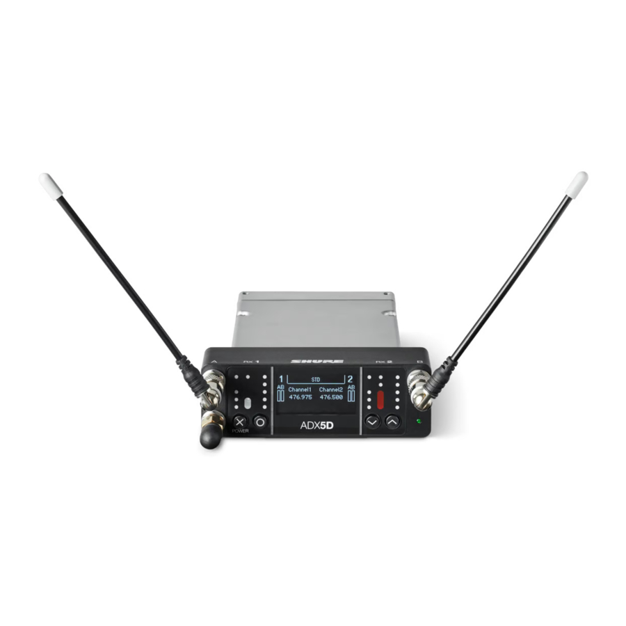
Features
The Axient® Digital ADX5D is a portable, dual-channel, digital wireless receiver.

- Wide tuning range up to 184 MHz (varies by region)
- High spectral efficiency due to advanced digital modulation scheme offers more wireless channels in available RF space
- True digital diversity reception per channel for drop-out resistance and excellent range
- Low latency, down to 2 milliseconds
- Networked control with Wireless Workbench software and ShurePlus™ Channels
- ShowLink® direct mode allows remote control of Axient® Digital transmitters without the need of additional equipment*
- Aux 3.5mm audio output provides connection to headphones or to a balanced line level input
- Three backplate connector options support various applications and connector types
* See Country-Specific Functionality Restrictions.
Optional Accessories
- ADX5BP-TA3
Standalone backplate - ADX5BP-DB15
DB15 backplate and spacer plate - ADX5BP-DB25
DB25 backplate and spacer plate - ADX5BS-L
L-type battery sled attachment - ADX5BS-AA
AA battery sled attachment - ADX5-MOUNT
Mounting plate with cold shoe - M3 screws (x2)
To attach cold shoe to mounting plate - ¼-20 screws (x2) and M2.5 screws (x2)
To attach mounting plate to third-party mounts
Hardware Callouts

- SMA inputs from Antenna A and Antenna B
RF connection for Antenna A and Antenna B. - Main mounting screws (M2.5x0.45)
Captive screws for mounting the receiver to other hardware. - SMA input from ShowLink® antenna
RF connection for networking via ShowLink.
Note: See Country-Specific Functionality Restrictions. - "Exit" (X) button
Push to return to the previous menu screen, hold to power the unit on or off. - "Enter" (O) button
Press to enter menu screens and confirm menu changes. - Control buttons
Use to navigate through parameter menus and to change settings. - Power LED
- Green = Unit is powered on
- Red = Unit is powered off
- Off = Unit is not connected to a valid power supply
- Audio level LEDs
Red, yellow, and green LEDs indicate average and peak audio levels. For more specific readings, use the in-display audio monitor. - Antenna status LEDs
Indicates status for both antennas:- Blue = Normal RF signal between the receiver and transmitter
- Red = Interference detected
- Off = No RF connection between the receiver and transmitter
Note: The receiver will not output audio unless one blue LED is illuminated.
- Channel quality LEDs
Displays signal-to-noise ratio of RF signal. When the RF signal is strong with a low level of noise, all five LEDs are lit; low levels of channel quality provide an early warning of potential problems, allowing you to switch to a clear frequency. - IR Sync LED
Indicates the receiver's IR port is aligned with a transmitter. - Infrared (IR) port
Align with a compatible transmitter's IR port during an IR Sync for automated tuning and setup. - Ambient Light Sensor
Automatically detects external lighting conditions. - Display
View menu screens and settings. Press any control button to activate the display. - USB-C port
Connect to a computer to update firmware.
Note: Device cannot be powered by USB. - 3.5mm output port
User-assignable audio output. - Backplate screw holes
Internally-threaded screw holes for securing interchangeable backplates. - Rear panel connector
Transfers data and power from compatible backplates.
Hardware Setup
Antenna Attachment

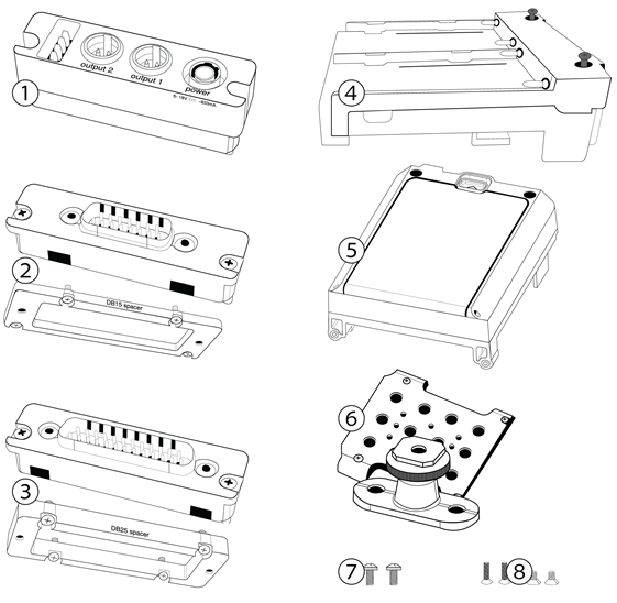
Rear Panel Kits
One of the major advantages of the slot-in receiver form factor is that they can be configured for multiple applications, including insertion into a camera or multi-coupler device, or for standalone use where power is provided by a battery distribution system (BDS) or battery sled. The rear panels manage power input, audio output, and data transfer between mating devices (e.g. cameras, multi-couplers, etc.). The spacer plates facilitate mounting in cameras, SuperSlot™ and UniSlot® multi-couplers, and audio bag organizer plates, as each of these devices have different dimensions and clearances for slot-in receivers.
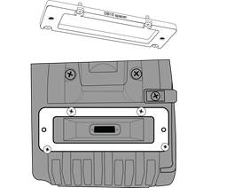
Attaching the Backplate
Align the captive Phillips screws with the threaded holes on the back of the ADX5D receiver and slide the backplate into place. Tighten screws to ensure a solid connection.

TIP: Backplates only align one way. You don't need to force it into place.
TA3 Backplate
The TA3 Backplate for ADX5D is designed to accommodate power input from an external source, audio output for the receiver, and optional interfacing with compatible battery sleds. The panel includes a 4-pin connector for mating with the battery sled, two TA3 (mini 3-pin XLR) audio output connectors, a 4-pin locking Hirose power input connector, and captive Phillips-head screws to mount/unmount the rear panel.

When connected, output 1 can be configured for analog or AES3 output in the device menu. Analog output 2 is disabled when AES3 is selected.
Since the receiver doesn't need to mate with an external device while being used with the standalone rear panel, a spacer plate is not required or included with the rear panel.
Connectors are (from left to right): 4-pin battery sled power input, TA3 audio outputs 1 and 2, and Hirose 4-pin power input.
Connecting a Power Supply
Connect a compatible 6-18V power supply to the power input. When multiple power sources are connected, the device will draw power from the Hirose connector, with the battery sled serving as backup. This allows for seamless switching between power supply and battery operations.


Always attach backplate to receiver before connecting power supply.
Note: The power supply does not charge rechargeable batteries.
Battery Sleds

ADX5BS-L and ADX5BS-AA battery sleds must be used with the ADX5BP-TA3 standalone rear panel, as this panel includes the 4-pin connector required for the two components to mate and pass power. The battery sled is then secured to the receiver using two screws on the rear of the sled, which ensures that the sled cannot fall off or be removed, and two screws from the front panel to stabilize the sled while on the receiver.
ADX5BS-L
The ADX5D can be powered by a single L type battery; when two batteries are installed, one can be replaced without interrupting operation. Battery runtime changes depending on the number, type, and capacity of the batteries used.

Insert the battery so that the contact points on the front face connect with the contacts at the rear of the battery sled bay until the latch moves into place. To remove the battery, push the latch down and pull the battery back and up.
ADX5BS-AA
The ADX5D can be powered by 6 AA batteries. Ensure all batteries are properly inserted as shown before powering on the device. Always power off the device fully before removing batteries.

AA Battery Runtimes
| Battery Type | Runtime |
| Alkaline | >1:30 |
| NiMH | >4:00 |
| Li Primary | >6:00 |
Note: Different operating and storage conditions can shorten or lengthen battery life.
DB15 Backplate
DB15 backplates are available for devices with 15-pin connectors, such as Sony video cameras. If only one audio channel is available, the 3.5mm connector on the bottom of the front plate can be used to output audio from channel 1, channel 2, channel 1+2 stereo, or channel 1+2 summed mono.
Note: See Country-Specific Functionality Restrictions.
The DB15 rear panel kit for ADX5D includes:

- A DB15 rear panel, with captive Phillips-head screws that make it easy to mount/unmount the rear panel without losing screws
- A DB15 spacer plate
Connecting to External Hardware
Attach the backplate and slot the ADX5D receiver into a compatible DB15 video camera. If needed, attach the included spacer plate to provide a proper fit.

DB25 Backplate
DB25 rear panels utilize a 25-pin D-Sub connector to transmit audio, video, data, and power. This connector type is commonly used on devices that require multiple interfacing paths in a small form factor, including SuperSlot™/UniSlot® devices.
Note: See Country-Specific Functionality Restrictions.

The DB25 rear panel kit for ADX5D includes:
- A DB25 rear panel, with captive Phillips-head screws that make it easy to mount/unmount the rear panel without losing screws
- A DB25 spacer plate
Connecting to External Hardware

Attach the backplate and slot the ADX5D receiver into compatible DB25 equipment, such as a video camera or multi-coupler. If needed, attach the included spacer plate to provide a proper fit.
Scan for Available Frequencies
Perform group and channel scans to find the best frequencies for your devices.
What are groups and channels
To minimize interference, Shure wireless systems organize RF bands into predefined groups and channels. An individual frequency is a channel. Channels that are unlikely to interfere with each other are compiled into groups.
Note: Because groups are band-dependent, some systems only have one available group. Single-group bands have the same RF performance as those with multiple groups.

Before you begin:
Turn off all transmitters for the systems you are setting up (this prevents them from interfering with the frequency scan).
Turn on potential sources of interference (other wireless systems or devices, computers, large LED panels, effects processors, and so on) so they are operating as they would be during the presentation or performance. The scan will detect and avoid any interference they generate.
Group Scan
Perform a group scan to find the group with the most available frequencies. Available frequencies can be automatically deployed to receiver channels and other networked components.
- Go to Channel Menu > Group Scan.
- Press O to scan the group.
- When the scan is complete, the number of frequencies found are shown on the display.
- Press O to assign frequencies to components on the network.
- To deploy frequencies to your transmitters, perform an IR sync.
Channel Scan
Perform a channel scan to find available frequencies within a group.
- Go to Channel Menu > Channel Scan
- Use the arrow buttons to choose the group you'd like to scan.
- Choose one of the following options:
- Find Next: Finds the next available frequency within the group
- Find Best: Finds the best available frequency based on RSSI
- Press O to confirm your frequency selection.
- To deploy frequencies to your transmitters, perform an IR sync.
Spectrum Scan
Scan the full RF spectrum for potential sources of interference, from the receiver or from connected control software. Use the control buttons to move the cursor across the spectrum and view frequency and level information.
- Set Zoom: Zoom in on the cursor point, up to 16x.
- Save: Store the current scan results.
- Recall: Restore the results of the most recently saved scan.
- Rescan: Perform a new scan.
IR Sync
Use IR Sync to form an audio channel between the transmitter and receiver.
Note: The receiver band must match the band of the transmitter.
- Power on the transmitter.
- Enter a receiver channel menu.
- Select Sync.
- Align the IR windows until the receiver IR sync LED illuminates red. When complete, Success appears. The transmitter and receiver are now tuned to the same frequency.


Note:
Any change to the encryption status on the receiver such as enabling/ disabling encryption or requesting a new encryption key, requires a sync to send the settings to the transmitter.
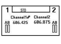
Home Screen
The home screen displays the most critical device and channel properties and statuses. From the main home screen, use the arrow buttons to navigate to the channel home screens. Press O to open the menu selection screen, or hold X to go to the shortcut menu.
Note: To change the information that appears on the device or channel home screens, go to Device Configuration > Display > Dev Home Options or Ch Home Options.
Icons
| Icon | Setting |
 | Battery runtime in hours and minutes or bar display |
 | Displayed when encryption is enabled |
 | Displayed when controls are locked. Icon will flash if access is attempted to a locked control (power or menu). |
 | ShowLink signal strength displays 0 to 5 bars |
 | Standard Transmission Mode |
 | High Density Transmission Mode |
 | Displayed when RF output is muted |
Menus and Configuration
The receiver uses a two-tier menu structure to support multiple channels:
- Device configuration menu: Items in this menu affect the overall performance of the receiver and apply to all channels globally.
- Channel menus: Each channel has its own menu allowing for independent channel configuration.
Note: If your receiver features a different menu structure, update to the latest firmware.
Shortcut Menu
To access the shortcut menu, hold the X button. Use the arrow keys to cycle through options, push O to confirm your selection.
| Shortcut | Function |
| Power Off? | Turn off the receiver. |
| Switch Channels | Quickly switch between channels without changing the se lected parameter. Note: Only available when the Shortcut menu is launched from within a channel menu. |
| 3.5mm Level | Adjust the 3.5mm output level from -60 to 12 in 1 dB steps. |
| Home | Open the device home screen. |
| Menu Lock | Use the locking feature to prevent accidental or unauthorized changes to controls and settings. Use the arrow buttons to change the lock status of the menu. |
| Rx1 Sync | Perform an IR Sync on Rx1. |
| Rx2 Sync | Perform an IR sync on Rx 2. Note: Not displayed in FD-C mode |
Device Configuration Menu
Use the following menu items and parameter settings to configure the receiver at the device level. From the following home screen, press O to see your menu options:
Use the arrows to select the menu of your choice, and press O to open that menu.
As you edit menu values, press O to save changes or press X to cancel without saving.
Device configuration menu map

Party Dial
Automatically set up transmitter for Party Dial, if applicable.
Switch between active channels. At-a-glance audio and battery life monitoring.
3.5mm Cfg
3.5mm Level
Adjust the headphone level from -60 to 12 in 1 dB steps.
3.5mm Limiter
Adjust the limiter threshold to prevent overdriving the headphone amp. 0 to -30 dB.
3.5mm Output
Choose an output mode. See 3.5 mm. Output Settings for more details.
3.5mm FD-S Options
When FD-S mode is engaged, select whether the headphone monitoring point is before or after FD-S selection.
Display
Brightness
Adjust the brightness of the display and LEDs. By default, ADX5D uses the ambient light sensor to automatically control the brightness based on the environment.
Note: Lower brightness settings consume less power.
Timeout
Offers options to turn off display and front panel illumination after 30 seconds, 1 minute (default), 2 minutes, 3 minutes, or 5 minutes.
LEDs
- Always On (default): All LEDs function normally.
- Always Off: Antenna status, audio, and channel quality LEDs off. Power status and IR alignment LEDs continue to function normally.
- Follow Display: Antenna status, audio, and channel quality LEDs follow the on/off behavior of the OLED display. Power status and IR alignment LEDs continue to function normally.
Dev Home Options
Select a device home screen.
Ch Home Options
Select a channel home screen.
Advanced
Technical configuration options.
Device Audio
Audio Format
Choose analog or AES3 audio format.
AES3 Rate
Configure sample rate of AES3 output.
Device RF
RF Band
Select the tuning band for the receiver. For proper operation, this should match the band of your transmitters.
Encryption
The receiver features Advanced Encryption Standard (AES 256) to ensure that only the receiver that is keyed to the transmitter can monitor the audio content. Use the menu buttons to select whether to encrypt the audio content and perform an IR sync to enable or disable the encryption.
Note: The encryption key icon (![]() ) will appear on the display of both the receiver and the transmitter when encryption is enabled.
) will appear on the display of both the receiver and the transmitter when encryption is enabled.
Trans Mode
Choose between standard and high density transmitter spacing. For more information about each option, see Transmission Modes.
Custom Groups
Configure, edit, or load (copy and distribute to other receivers on the network) custom frequency groups.
TV Format
Adjust TV bandwidth to match regional standards.
Device ID
Assigning custom names or IDs helps with monitoring and organizing when the receiver is part of a large system. Use the arrow buttons to select or edit an ID.
ShowLink®
Note: See Country-Specific Functionality Restrictions.
SL Mode
Select a ShowLink® mode:
- Direct mode: Control parameters of up to 16 registered ADX-series transmitters.
- Network mode: Connect to an existing Shure control network via one or more AD610 access points.
For more information on each ShowLink® mode, see ShowLink® Remote Control.
SL Current Channel
When ShowLink® mode is on, displays the current channel.
SL Direct Config
The following settings apply when the ADX5D is operating in ShowLink® direct mode:
- SL Ch Selection: Choose whether channel selection is automatic or manual.
- SL Ch (Manual): Select a ShowLink® channel.
- SL Ch Mask (Auto): Set automatic channel selection to use or avoid individual channels.
- SL Capacity: Displays the number of devices connected to the ShowLink® network as well as the total capacity of the network.
SL Network Config
The following settings apply when the ADX5D is operating in ShowLink® network mode:
- SL Test (Rx): See the ADX5D <=> Access Point ShowLink® status as the ADX5D moves around the working area. For more information, see ShowLink Test.
- SL Net ID (Client): See and configure the ShowLink® network client ID.
Access Ctrl
View the status of access control (enabled or disabled). If enabled, you can disable access control here. Use Wireless Workbench or other Shure control software to enable access control.
If access control is enabled, control applications such as Wireless Workbench and ShurePlus Channels supply a PIN in order to remotely manage the device. That access control PIN appears in this menu. The initial PIN can be configured by Wireless Workbench; see the Wireless Workbench help for more information on this.
Net Browse
Use the network browser utility to view all Shure devices on a network.
By Model
Arranges the network browser results by model name.
By FW Version
Arranges the network browser results by firmware version.
HW Identify
Send a hardware identification message to control applications, like Wireless Workbench, so you can locate your device in the application.
Tx Fw Update
Align transmitter IR window and select to update transmitter firmware.
3rd Party Control
Turn third-party control support On or Off. Reboot to apply changes.
*See Country-Specific Functionality Restrictions.
About
Provides a detailed list of build specifications and vital statistics for the receiver.
Factory Reset
Resets all receiver parameters to factory settings.
All current settings will be cleared during the reset and the receiver will reboot.
User Presets
Presets store all receiver settings to provide a quick way to configure a receiver or switch between several different setups. Up to 4 presets can be stored in receiver memory. Manage and load presets with the control buttons.
- Restore Preset: Load existing preset
- Save Preset: Save the current settings as a preset
- Delete Preset: Delete a preset
Menu Lock
Use the locking feature to prevent accidental or unauthorized changes to controls and settings. Use the arrow buttons to change the lock status of the menu.
Power Status
View the voltage, connected power sources, and active power source for the receiver.
Channel Menu
Use the following menus and parameters to configure the receiver channels. From either of the following home screens, press O to see the corresponding channel's options:

Use the arrows to select the menu of your choice, and press O to open that menu.
As you edit menu values, press O to save changes or press X to cancel without saving.
Channel menu map

New Freq
Press O to deploy a new frequency when using a spectrum manager as a frequency server.
Note: You won't see this menu option if you don't have a frequency server assigned to the receiver.
Radio
Set a group, channel, and frequency.
Channel Scan
Finds available channels within the selected group:
- Find Next: Selects the nearest available channel
- Find Best: Selects the channels with the best RF noise floor
Group Scan
Scans the selected group to find all available channels.
Channel Name
Assigning unique names to each channel helps with identification and organization when the receiver is part of a large system. Use the arrow keys to assign or edit the channel name.
Sync
Sync a transmitter to the receiver channel. You can also see information about the IR sync process, including when a sync is in progress, whether a sync was successful, and some helpful tips if it failed.
Advanced
Technical configuration options.
Spectrum Scan
Choose to perform a scan or recall a previously saved scan, if one is available.
RF Level
See finer-resolution details about the RF signal strength.
Interference Mgmt
Select interference detection setting for the channel. For more information on each setting, see Interference Detection.
Frequency Diversity
Configure frequency diversity for handheld or bodypack transmitters. Choose between:
- Combining: For use with a single ADX2FD handheld transmitter
- Selection: For use with a pair of AD1 or ADX1 series transmitters For more information on these settings, see Frequency Diversity.
IR Presets
Configuring IR presets allows all transmitter parameters to be automatically set from the receiver during an IR sync. Use the arrow buttons to select and edit transmitter parameters from the preset list. Select No Change to keep existing settings.
FD-S Advanced
View and adjust the advanced FD-S options. For more information, see FD-S Advanced Settings.
Talk Switch
Set receiver output signal routing options for talk switch control from a transmitter. For more information about using a talk switch with an Axient® Digital transmitter, see the talk switch user guide.
Standby
Put this channel on standby to conserve power when you aren't using it.
Tx Details
Displays build details and vital statistics for the transmitter being received.
Tx Slots
View and configure transmitter properties. Press O to select a slot and see further actions for that slot. For more details about transmitter slots, see Assigning Transmitters to Slots.
![]() Indicates a ShowLink® capable transmitter
Indicates a ShowLink® capable transmitter![]() ShowLink® status (ShowLink® transmitters only)
ShowLink® status (ShowLink® transmitters only)![]() RF status. If the icon appears, RF output is on (ShowLink® transmitters only)
RF status. If the icon appears, RF output is on (ShowLink® transmitters only)![]() Battery information (ShowLink® transmitters only)
Battery information (ShowLink® transmitters only)
 Indicates a ShowLink® capable transmitter
 ShowLink® status (ShowLink® transmitters only)
 RF status. If the icon appears, RF output is on (ShowLink® transmitters only)
 Battery information (ShowLink® transmitters only)
Sync
Assign a transmitter to the selected slot.
Unlink
Remove a transmitter from the selected slot.
Flash (ShowLink® transmitters only)
Flashes the display of a transmitter linked to the receiver.
Activate (ShowLink® transmitters only)
Press O to send RF mute to all other slots.
SL Test
Press O to see the transmitter's ShowLink® status as the portables move around the working area. For more information, see ShowLink® Test.
Audio
Gain/Mute
You can individually control the gain and audio output in real time for each channel.
- Gain: Adjust the gain in 1dB increments while performing a sound check using typical audio input signal levels and monitor the audio meter LEDs. Reduce the gain if the red LED triggers repeatedly.
- Output: Select On or Mute for the receiver audio output.
Tone Generator
Provides a continuous audio signal tone for testing and troubleshooting. Use the arrow buttons to select a level and frequency for the tone, and set the level to Off to stop the generator.
ShowLink® Remote Control
ShowLink® remote control uses a wireless network connection to enable real-time remote parameter adjustments for select portable Axient® devices. Whether performers are in the middle of a presentation or off stage waiting for their cue, ShowLink® lets you make crucial changes to transmitter settings without interrupting the performers.
Note: See Country-Specific Functionality Restrictions.
ADX5D ShowLink® Modes
To update the ShowLink® mode, go to Device Configuration > ShowLink > SL Mode. ADX5D ShowLink® modes:
- Direct (default)
- Network
- Off
ShowLink modes: When to use
| Mode | Reasons for use | Needed equipment | Example use case |
| Direct mode | To establish a connection between a single ADX5D and one or more transmit ters | ADX5D ShowLink enabled trans ® mitters | Crew has a small setup with a few ADX transmitters and no need to use Wireless Workbench or connect to a larger network. |
| Network mode | To connect ADX5D to an ex isting network, control the receiver and any linked de vices with software (such as Wireless Workbench), and perform frequency mitigation or coordination for any linked devices | ADX5D AD610 ShowLink access ® point Optionally, other AD trans mitters and receivers | Studio or filming site with a mix of carts and racks of other gear and computers or tablets running control soft ware. |
| Off mode | You don't need to connect to Wireless Workbench or a larger network and want to extend battery life by turning off non essential power con suming features or avoid us ing the 2.4 GHz spectrum | ADX5D | Crew has transmitters that aren't ShowLink enabled. ® Users are transmitting audio but not connecting to a larg er network or remotely modi fying parameters. |
Direct Mode
Operate your ADX5D in direct mode to remotely control parameters of registered ADX transmitters without connecting to a larger installation or using control software. When ADX5D is in direct mode, you can control up to 16 Axient® Digital ADX-series transmitters (8 per channel) from a single ADX5D receiver.
Note: An ADX5D in direct mode has no connection to any control applications (e.g. Wireless Workbench or Channels) or devices other than transmitters (e.g. Axient® Digital receivers or AD610 access points).
Automatic or Manual ShowLink® Channel Selection
When your device is in direct mode, the ShowLink® radio will scan the 2.4 GHz spectrum and pick the best channel to operate on. The device will use this channel until the next boot time. You can update your settings to choose a specific channel instead by going to Device Configuration > ShowLink > SL Direct Config > SL Ch Selection, selecting Manual, and entering the ShowLink® channel you want the device to operate on.
ShowLink Channel Mask
If your receiver is in automatic channel selection mode, you can set a ShowLink® channel mask to dictate channels to use or avoid. Go to Device Configuration > ShowLink > SL Direct Config > SL Ch Mask (Auto) to select "Use" or "Avoid" for each individual ShowLink® channel.
Network Mode

- AD-series transmitter (no ShowLink)
- ADX-series transmitter(ShowLink enabled)
- ADX5D
- AD610
- Network switch
- Computer
Use network mode to connect the ADX5D to an existing Shure network and take advantage of the full features of an Axient® Digital receiver, including interference management and frequency coordination via control software such as Wireless Workbench. In network mode, your ShowLink® communications are routed through an AD610 access point, which increases device capacity and ShowLink® range as well as enabling features that depend on connection to a larger network.
Note: The ADX5D is compatible with the AD610 ShowLink® access point.
Set Up an AD610 and Choose a Network Host ID
To use the ADX5D in network mode, you must connect an AD610 ShowLink® access point to your network and set a network host ID, which grants access to ADX5Ds with a matching client ID. You can control up to 24 Axient® Digital devices with each AD610.
Note: Update your AD610 to the latest firmware and download the latest version of Wireless Workbench before connecting your ADX5D to the network.
Use the following steps to set up an AD610 ShowLink® access point and choose a network host ID:
- Connect your AD610 to your network using a Class 1 Power over Ethernet (PoE) port.
- Right-click the device in Wireless Workbench and open the device properties.
- Set the ShowLink® network host ID (e.g. A.B.C.D).
Repeat this process for any other AD610s you have on the network that you want to act as a gateway for an ADX5D.
Turn On ADX5D Network Mode and Set the Client ID
An ADX5D in network mode uses a client ID to join networks with an AD610 that has a matching host ID. Once you have an AD610 on your network and a network host ID chosen, set your ADX5D to network mode and set the client ID to match the host ID.
Note: You must be using network mode in order to control this device with Wireless Workbench.
To turn on network mode and set the client ID:
- In the ADX5D Device Configuration menu, go to ShowLink > SL Mode and select network mode.
- Choose the client ID (e.g. A.B.C.D) that matches with your AD610.
- The ADX5D reboots to apply the new settings.
If the ADX5D is already operating in network mode, go to Device Cfg > ShowLink > SL Network Cfg > SL Net ID (Client) and choose the client ID that matches the AD610. The ADX5D reboots to apply the new setting.
ShowLink® Test
Perform a ShowLink® test to find the boundaries of the ShowLink® coverage area between linked devices. When a ShowLink® test is activated, a five bar display indicating the link quality is shown on the screen. As the devices are moved apart, the number of bars will decrease. ShowLink® control is maintained as long as 1 bar is displayed.
If the device is beyond the coverage range, ShowLink® control is not possible. However, the audio signal will not be affected or interrupted as long as the receiver is within range of the RF signal.
To improve coverage, adjust the location of your devices or place additional access points to extend coverage.
Tip: During a ShowLink® test, press O to drop a marker in Wireless Workbench.
Test coverage of linked transmitters
Perform a ShowLink® test from the Tx Slots menu to plot the status of a linked transmitter's ShowLink® coverage. When your device is in direct mode, this function measures the coverage between your transmitter and the ADX5D; when your device is in network mode, this function measures the coverage between your transmitter and the AD610 it is associated with.
- Go to the channel menu and select Tx Slots > SL Test.
- Position your equipment where you expect it to be when in use.
- On the receiver, press the O button to start the test.
- Walk the transmitter around the coverage area. Monitor the number of bars displayed and the state of the ShowLink® icon. Coverage boundaries are indicated by 0 bars displayed or the ShowLink® icon is empty.
- Press X to exit the ShowLink® test.
Test coverage between AD610 and receiver (network mode only)
To test ShowLink® coverage between an ADX5D in network mode and an AD610 access point:
- From the Device Configuration menu, navigate to SL Test.
- Position the AD610 where you expect it to be when in use.
- On the receiver, press the O button to start the test.
- Walk the receiver around the coverage area. Monitor the number of bars displayed and the state of the ShowLink® icon.
Coverage boundaries are indicated by 0 bars displayed or the ShowLink® icon is empty. - Press X to exit the ShowLink® test.
Assigning Transmitters to Transmitter Slots
Each receiver channel contains 8 transmitter slots to control the RF signals passed by the receiver. Transmitters can be assigned to the channel slots or "registered" with the receiver.
For added protection from interference, the receiver will issue a warning or block signals from any transmitters that aren't registered.
To assign a transmitter to a receiver channel:
- From the Channel menu, go to Tx Slots.
- Use the arrow buttons to scroll to an available transmitter slot. If the slot is occupied, syncing will overwrite the existing transmitter.
- Use the arrow buttons to select Sync and press O.
When the sync is complete, the transmitter will be assigned to the slot. The transmitter will remain assigned to the slot until it is unlinked. To remove a transmitter from a slot, use the arrow buttons to select the slot. Then, use the arrow buttons to select Unlink and press O.
Party Dial
Use party dial to quickly switch between active transmitters from a single menu. In party dial, 2 transmitters can be live at any time, and you can switch between channel IDs without having to confirm the change.
Party dial limits your available frequencies to those in a single group. Before entering party dial, you must select a group for your transmitters. You can perform a group scan or create a custom group to define frequencies for each transmitter.
To open party dial, go to Device Cfg > Party Dial. Note that entering party dial will set the following on your receiver:
- Encryption turns off
- Frequency diversity turns off
- Unregistered transmitter action is allowed
- All transmitter slots are unlinked
These changes persist if you exit party dial.
Navigating in party dial
Each device channel can receive audio from 1 transmitter at a time. Press the arrow keys to change the selected channel ID. Changes are applied immediately, and device information populates shortly thereafter. Press Enter to switch between receiver channel 1 and receiver channel 2.

- Receiver channel indicator
1 or 2. Press Enter to switch to the other channel - Device ID for selected transmitter
Quickly identifies each connected device - Group ID
Must be set outside of party dial - Channel ID
Switch between channel IDs using the arrow keys - Battery time remaining
For the selected transmitter - Audio meter
For more specific readings, use the in-display audio monitor.
Custom Groups
In party dial, you can quickly move between all available RF channels in a selected group. To limit that group to a specific set of channel IDs, you can pre-select frequencies for your transmitters and assign them to a custom group.
Note: Party dial does not necessarily have to employ custom groups. You can use pre-programmed groups, but be aware that there may be extra channel IDs in that pre programmed group. If there are extra channel IDs in your group, you will have to scroll past them when in party dial to reach the channel IDs assigned to your transmitters.
Set Up Custom Groups in Wireless Workbench
Use the coordination tools in Wireless Workbench determine the best frequencies for your needs and assign those frequencies to a custom group.
- Set up your ADX5D to sync custom groups (Channel > Advanced > IR Presets > Custom Groups > Sync).
- Perform a frequency coordination.
- Create a custom group of those frequencies (see the Custom Groups topic in the Wireless Workbench® help system for these steps).
- IR sync all transmitters to assign custom group and channel information.
Set Up Custom Groups on the ADX5D
You can also set custom groups using just the ADX5D receiver if you don't use or have access to Wireless Workbench.
- Go to Device Cfg > Advanced > Device RF > Custom Groups.
- Manually set the group ID, channel ID, and frequency. Use the arrows to select each field, press enter to edit, press enter again to confirm.
- Load copies custom group information to all other networked AD receivers with the same tuning band.
- Clear removes custom group information from your device, but does not affect networked receivers.
- Perform a sound check. Use the microphone offset feature to adjust the gain on each transmitter.
- Go to Device Cfg. > Party Dial.
Note: If party dial is engaged following a standard group/channel scan, all frequencies in the selected group will be included. Blue LEDs confirm audio is being received on the selected channel.
Transmission Modes
The receiver offers two transmission modes to efficiently manage the available spectrum used by the transmitters.
Standard Mode
Standard mode employs channel spacing that allows for the operation of transmitters at various power levels.
Standard mode is ideal for situations where spectrum is not limited or when you need to operate transmitters at higher power levels to increase range.
High Density Mode
High density mode creates additional bandwidth for more channels in crowded RF environments by transmitting at 2 mW RF power and narrowing the modulation bandwidth.
High density mode is ideal for applications where many channels are needed in a confined area, transmission distances are short, and the number of available frequencies is limited.
Note: Operation mode varies according to region.
Selecting a Transmission Mode
- From the Device Configuration menu, go to Device RF > Trans Mode.
- Press O to enable editing. Use the arrow buttons to select a mode.
- Press O to save.
Frequency Diversity
Frequency diversity enables seamless, uninterrupted audio for mission-critical applications. Frequency diversity works by transmitting the audio on two independent frequencies from an ADX2FD handheld transmitter or from 2 AD/ADX series transmitters.
When operated in frequency diversity mode, the receiver uses two frequencies to provide a single channel of audio. If one frequency experiences interference, the audio from the other frequency is used to prevent dropouts or interruption of the audio.
Using frequency diversity in conjunction with interference detection provides an additional layer of protection for the audio signal.
- From the channel menu: Advanced > Frequency Diversity.
- Choose one of the following frequency diversity modes:
- Combining: For use with a single ADX2FD handheld transmitter
- Selection: For use with a pair of AD/ADX series transmitters
- Press O to save.
- Perform an IR sync between the receiver and the transmitters.
FD-S Advanced Settings
| Setting | Description |
| Override / Lock to | Enables the ability to override the FD S algorithm and manu ally select the receiver. |
| Monitor 3.5mm Output | Configures the 3.5mm output to monitor pre- or post- FD-S selection. |
| Audio Evaluation | When OFF: Only the RF assessment to the FD-S pairs is made. Recommended when two separate inputs are in use. When ON: If both RF channels in the FD S pair pass RF as sessment, an optional assessment of the audio signal level is made. If the difference in the audio level is significant, the algorithm selects the higher of the two signals. |
Interference Management
See Country-Specific Functionality Restrictions.
In the event of signal degradation, interference management technology provides options to move to a clean, compatible frequency, either manually or automatically.
Respond to an alert by manually selecting a new frequency, or allow the Spectrum Manager or Wireless Workbench to automatically deploy a backup frequency the instant interference is detected.
Tip: To dismiss a interference alert, select the affected channel, and then select Dismiss.
Setting the Detection Mode
The detection mode determines how the receiver will switch to a clear frequency in the event of interference.
- Select a channel and navigate to: Advanced > Interf. Mgt > Detection Mode
- Choose one of the following modes:
- Manual: Select a frequency manually when interference occurs
- Automatic: Allow the receiver to automatically select a new frequency
Unregistered Transmitter Action
The unregistered transmitter setting determines how the receiver reacts to the presence of unregistered transmitters, which can be a potential source of interference. If a transmitter is not listed in the receiver's Tx Slots, then that transmitter is considered unregistered to the receiver channel.
From the Interf. Mgt menu, choose one of the following options:
- Allow: The receiver will pass audio from the unregistered transmitter
- Warn: The receiver will display a warning when an unregistered transmitter is detected
- Block: The receiver will treat the unregistered transmitter as interference and will block the audio
Frequency Server
The frequency server option allows you to assign a networked Spectrum Manager as a server for clear frequencies in the event of interference.
- From the Interf. Mgt menu, select Freq. Server
- Press O to enable editing and select a Spectrum Manager from your network.
- Press O to save.
3.5 mm. Output Settings
Choose a mode for your 3.5 mm. output depending on which equipment you use with the receiver.

*When ADX5D is operating in FD-S with Pre selection chosen, the sum will continue to output the Post FD-S audio
Firmware
Firmware is embedded software in each component that controls functionality. Installing the latest version of firmware updates the receiver to incorporate additional features and enhancements. New versions of the firmware can be uploaded and installed using the Shure Update Utility tool. Software is available for download from http://www.shure.com/firmware.
Firmware Versioning
When you update receiver firmware, update your transmitters to the same firmware version to ensure consistent operation.
The firmware of all devices has the form of MAJOR.MINOR.PATCH (e.g., 1.2.14). At a minimum, all devices on the network (including transmitters) must have the same MAJOR and MINOR firmware version numbers (e.g., 1.2.x).
Updating the Receiver Firmware
Ensure that receiver power and network connections are maintained during a firmware update. Do not turn off the receiver until the update is complete.
- Open the Shure Update Utility.
- Click Check for Updates to view new versions available for download.
- Select the updates and click Download.
- Connect your receiver to your computer via USB-C.
- Open the Update Devices tab to view all Shure devices connected to the computer.
- Select your receiver.
- Press Send Updates to download the latest firmware to the receiver.
Updating the Transmitter Firmware
- From the Device Configuration menu of the receiver: Tx FW Update.
- Turn on the transmitter and align the IR sync windows on the transmitter and receiver. The red alignment LED will illuminate when alignment is correct.
- Maintain alignment and press O on the receiver to begin the update.
Alignment must be maintained during the entire update cycle. Percentage of update progress appears on the receiver display.
Troubleshooting
| Problem | Solution |
| No sound | Make sure the receiver and transmitter are powered on and are set to the same channel Perform a scan and sync to ensure the transmitter and receiver are set to the same group and channel Make sure the transmitter and receiver are in compatible bands Check that all cables and connectors are working correctly Re-sync all receivers and transmitters after enabling or disabling encryption |
| Faint sound, distortion | Adjust the system gain on the receiver. Ensure the output level of the receiver corresponds to the mic/line input setting of the mixing console, amplifier, or DSP Check that all cables and connectors are working correctly |
| Lack of range, unwanted noise bursts, or dropouts | Make sure the receiver antennas are securely attached Perform a group or channel scan to find the best open frequency. Perform a sync to transfer the setting to the transmitter For multiple systems, check that all systems are set to channels in the same group (systems in different bands do not need to be set to the same group) Maintain a line of sight between transmitter and receiver antennas Move or point receiver antennas away from metal objects or other sources of RF interference (such as LED walls, computers, digital effects, network switches, wireless access points, network cables and Personal Stereo Monitor (PSM) wireless systems) Eliminate RF overload: Move the transmitter further away from the receiver—at least 6 m (20 ft) Reduce the transmitter RF power level If you are using active antennas, reduce antenna or amplifier gain Use omnidirectional antennas |
| Cannot add network ID in AD610 properties panel in Wireless Workbench | Install the latest version of Wireless Workbench Update AD610 to latest firmware |
| Experiencing ShowLink interference ® | Move or point receiver antenna away from metal objects or other sources of RF interference Reboot the ADX5D |
| Not able to set ShowLink mode on ADX5D ® | Verify that your attached backplate and mode enable ShowLink - ® see Country-Specific Functionality Restrictions. |
| ADX5D not appearing in Wireless Workbench | Ensure that there is an AD610 connected to your network with a network ID set Check that the ADX5D is in network mode Verify that the ADX5D's client ID matches the AD610s network ID Install the latest version of Wireless Workbench Reboot the ADX5D |
| Linked transmitters not appearing in Wireless Workbench | Perform a scan and sync to ensure the transmitter and receiver are set to the same group and channel Make sure the transmitter and receiver are in compatible bands Update transmitter to latest firmware |
Notifications
The following alerts are displayed in the ADX5D menu screens. If the suggested actions do not resolve the issue, contact your Shure customer service representative.
Device Notifications
| Message | Action |
| RF Power Overload | Confirm there are no high power transmitters in the vicinity |
| Over Temperature | Power off and allow device to cool before resuming use |
| SM Offline | Confirm the connected spectrum manager is powered on and online |
| Back Plate Failure | Power off the unit Remove the back plate Confirm connectors are not obstructed or damaged Reconnect the back plate |
| FPGA Unresponsive | Reboot the unit If the alert is still reported, attempt to update the firmware. If the condition persists, contact support. |
| SL Proc. Failure | Reboot the unit If the alert is still reported, attempt to update the firmware. If the condition persists, contact support. |
| 3.5mm Lim. Engaged | Adjust/reduce the following: 3.5mm level System gain Tx offset Source audio |
| 3.5mm Overload | Confirm the 3.5mm output format is appropriate for the connected output device Adjust the 3.5mm limiter Check the connection for shorts |
| Low Voltage | Check the Power Status in the device configuration menu to toggle this alert on/off and to set the power threshold for the alert. |
Channel Notifications
| Message | Action |
| Interference | Perform a group or channel scan and sync the transmitter For multiple systems, check that all systems are set to channels in the same group (sys tems in different bands do not need to be set to the same group). Maintain a line of sight between transmitter and receiver antennas. Move or point receiver antennas away from metal objects or other sources of RF interfer ence (LED walls, computers, digital effects, network switches, network cables and Person al Stereo Monitor (PSM) wireless systems). Eliminate RF overload (see below). |
| Unregistered AD Tx | Ensure all transmitters are assigned to transmitter slots. |
| Multiple Tx Active | Enter the Channel > Tx Slots menu. Select the desired transmitter and select Activate. |
| Encryption Mismatch | Re-sync the transmitter with the intended receiver. |
| Tx Overload | Confirm the input pad and transmitter offset are appropriate for the source audio. |
| Tx Muted | Unmute the active transmitter. |
| Tx RF Muted | Disable RF mute on the active transmitter. |
| Firmware Mismatch | Use Device Cfg > Tx FW Updateto update the transmitter firmware. |
| Rx Muted | Navigate to Channel > AudioOutput and change the mode to On |
| Tx Battery Hot | Remove the transmitter from heat and replace the battery to let it cool down. If condition persists, the transmitter will shut down. Replace the battery and ensure unit is operating in normal temperature environments. |
Contact Customer Support
Didn't find what you need? Contact our customer support to get help.
Receiver Frequency Bands
| Band | Frequency Range ( MHz) |
| G53 | 470 to 510 |
| G54 | 479 to 565 |
| G55† | 470 to 636* |
| G56 | 470 to 636 |
| G57 (G57+) | 470 to 616* (614 to 616*** ) |
| G62 | 510 to 530 |
| G63 | 487 to 636 |
| H54 | 520 to 636 |
| K53 | 606 to 698* |
| K54 | 606 to 663** |
| K55 | 606 to 694 |
| K56 | 606 to 714 |
| K57 | 606 to 790 |
| K58 | 622 to 698 |
| L54 | 630 to 787 |
| L60 | 630 to 698 |
| P55 | 694 to 703, 748 to 758, 803 to 806 |
| R52 | 794 to 806 |
| JB | 806 to 810 |
| X51 | 925 to 937.5 |
| X55 | 941 to 960 |
| X56 | 960 to 1000 |
*With a gap between 608 to 614 MHz.
**With a gap between 608 to 614 MHz and a gap between 616 to 653 MHz.
***Selecting the G57+ band extends the G57 band with 2 MHz of additional spectrum between 614 to 616 MHz. Maximum transmitter power is limited to 10mW between 614 to 616 MHz.
†Operation mode varies according to region. In Brazil, High Density mode is used. The maximum power level for Peru is 10mW.
Specifications
UHF Specifications
RF Carrier Frequency Range
470–1000 MHz, varies by region (See frequency table)
Working Range (line of sight)
Note: Actual range depends on RF signal absorption, reflection, and interference
Standard Density Mode 75 m (246 ft)
High Density Mode 40 m (131 ft)
RF Sensitivity
−90 dBm at 10-5 BER
RF Tuning Step Size
25 kHz, varies by region
Image Rejection
>70 dB, typical
Spurious Rejection
>80 dB, typical
Connector Type
SMA (Shell=Ground, Center=Signal)
Impedance
50 Ω
ShowLink® Specifications
Frequency Range
2.40 to 2.4835 GHz (16 Channels)
Working Range
30m
Note: Actual range depends on RF signal absorption, reflection, and interference
Connector Type
SMA (Shell=Ground, Center=Signal)
Impedance
50 Ω
ShowLink® Antenna Power
2.5 dBm EIRP
Antenna Type
1 Omni 2.4 GHz
Network Type
IEEE 802.15.4
Audio Output
Gain Adjustment Range
−18 to +42 dB in 1 dB steps (plus Mute setting)
Impedance
66 Ω, Typical, TA3 Out
Full Scale Output ( 200K Ωload)
+9 dBV
Phantom Power Protection
Yes
Note: 3.5mm output does not have phantom power protection
Audio Frequency Response
Note: Dependent on microphone type
20 Hz – 20 kHz
Dynamic Range
129 dB
Total Harmonic Distortion
0.0006% at -6 dBFS, 1 kHz,
System Audio Polarity
Positive pressure on diaphragm produces positive voltage on audio+ with respect to audio-
Analog Output Latency
Standard Density Mode 2.08 ms
High Density Mode 2.96 ms
USB Input (used for firmware updates)
Connector Type
USB-C
USB Protocol
USB 2.0
USB Role
Peripheral (upstream-facing port)
USB Power Delivery
None
Power
DC Power Requirements
6V DC to 18V DC
Thermal Power Dissipation
| maximum | 4.8 W (18 V in, full brightness, all audio full scale out, and RF channels active) |
| nominal | 4W (12 V in, no outputs, no linked transmitters) |
| minimum | 2.3 W (6.5V in, both channels in standby) |
Mechanical Specifications
Operating Temperature Range
-18°C (0°F) to 50°C (122°F)
Note: Battery characteristics may limit this range.
Storage Temperature Range
-29°C (-20°F) to 65°C (149°F)
Dimensions
29 x 88 x 108 mm H x W x D (No backplate)
Weight
0.24 kg (0.53 lbs), without antennas or backplate
Housing
Machined aluminum
Dimensions

Pinout Diagrams
DB15

DB25

TA3M

Hirose

IMPORTANT SAFETY INSTRUCTIONS
- READ these instructions.
- KEEP these instructions.
- HEED all warnings.
- FOLLOW all instructions.
- DO NOT use this apparatus near water.
- CLEAN ONLY with dry cloth.
- DO NOT block any ventilation openings. Allow sufficient distances for adequate ventilation and install in accordance with the manufacturer's instructions.
- DO NOT install near any heat sources such as open flames, radiators, heat registers, stoves, or other apparatus (including amplifiers) that produce heat. Do not place any open flame sources on the product.
- DO NOT defeat the safety purpose of the polarized or grounding type plug. A polarized plug has two blades with one wider than the other. A grounding type plug has two blades and a third grounding prong. The wider blade or the third prong are provided for your safety. If the provided plug does not fit into your outlet, consult an electrician for replacement of the obsolete outlet.
- PROTECT the power cord from being walked on or pinched, particularly at plugs, convenience receptacles, and the point where they exit from the apparatus.
- ONLY USE attachments/accessories specified by the manufacturer.
- USE only with a cart, stand, tripod, bracket, or table specified by the manufacturer, or sold with the apparatus. When a cart is used, use caution when moving the cart/apparatus combination to avoid injury from tip-over.
- UNPLUG this apparatus during lightning storms or when unused for long periods of time.
- REFER all servicing to qualified service personnel. Servicing is required when the apparatus has been damaged in any way, such as power supply cord or plug is damaged, liquid has been spilled or objects have fallen into the apparatus, the apparatus has been exposed to rain or moisture, does not operate normally, or has been dropped.
- DO NOT expose the apparatus to dripping and splashing. DO NOT put objects filled with liquids, such as vases, on the apparatus.
- The MAINS plug or an appliance coupler shall remain readily operable.
- The airborne noise of the Apparatus does not exceed 70dB (A).
- Apparatus with CLASS I construction shall be connected to a MAINS socket outlet with a protective earthing connection.
- To reduce the risk of fire or electric shock, do not expose this apparatus to rain or moisture.
- Do not attempt to modify this product. Doing so could result in personal injury and/or product failure.
- Operate this product within its specified operating temperature range.

Voltages in this equipment are hazardous to life. No user serviceable parts inside. Refer all servicing to qualified service personnel. The safety certifications do not apply when the operating voltage is changed from the factory setting.

Documents / Resources
References
Download manual
Here you can download full pdf version of manual, it may contain additional safety instructions, warranty information, FCC rules, etc.
Advertisement


Need help?
Do you have a question about the ADX5D and is the answer not in the manual?
Questions and answers