Table of Contents
Advertisement
Available languages
Available languages
Quick Links
CL I MATI ZZ AT OR I D'A R IA M ONO SPLIT- R3 2
MAN U AL E DI U SO E INSTA LLA Z IONE
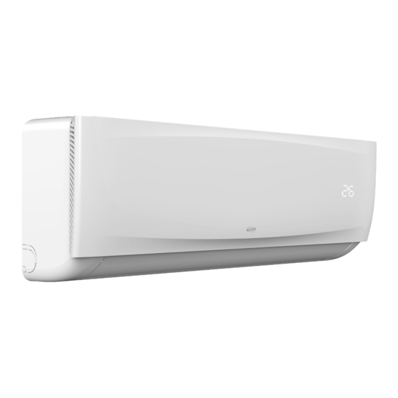
UNITÀ INTERNA
NEWAGE 9000 UI
NEWAGE 12000 UI
NEWAGE 18000 UI
Leggere attentamente il presente manuale prima di installare e usare il climatizzatore e conservarlo per
futuri riferimenti.
N E WA GE
V 11/22
UNITÀ ESTERNA
NEWAGE 9000 UE
NEWAGE 12000 UE
NEWAGE 18000 UE
IT
Advertisement
Table of Contents

Related Manuals for Argo NEWAGE 12000 UI


Summary of Contents for Argo NEWAGE 12000 UI
- Page 1 MAN U AL E DI U SO E INSTA LLA Z IONE UNITÀ INTERNA UNITÀ ESTERNA NEWAGE 9000 UI NEWAGE 9000 UE NEWAGE 12000 UI NEWAGE 12000 UE NEWAGE 18000 UI NEWAGE 18000 UE Leggere attentamente il presente manuale prima di installare e usare il climatizzatore e conservarlo per futuri riferimenti.
-
Page 2: Table Of Contents
INDICE Avvertenze generali Precauzioni di base Informazioni sull’uso Descrizioni delle parti Guida all’uso del telecomando Guida alla WiFi (optional) Pulizia e manutenzione Risoluzione dei problemi Note per l’installazione Installazione unità interna Installazione unità esterna Note di manutenzione Avvertenze per lo specialista del circuito frigorifero REQUISITI PERSONALE ADDETTO A INSTALLAZIONE E MANUTENZIONE Tutto il personale che effettua operazioni di installazione e/o manutenzione sulle unità... -
Page 3: Avvertenze Generali
AVVERTENZE GENERALI Apparecchio contenente gas Prima di installare e utilizzare l’unità, leggere le istruzioni. leggermente infiammabile R32. Prima di installare l’unità, leggere il Per eventuali riparazioni, rivolgersi sempre ad manuale di installazione. un Centro Assistenza autorizzato e attenersi rigorosamente a quanto contenuto nel Manuale di servizio. -
Page 4: Precauzioni Di Base
PRECAUZIONI DI BASE ATTENZIONE • Questo apparecchio può essere utilizzato da bambini di età non inferiore a 8 anni e da persone con ridotte capacità fisiche, sensoriali o mentali, o prive di esperienza e della necessaria conoscenza, purché sotto sorveglianza oppure dopo che le stesse abbiano ricevuto istruzioni relative all’uso sicuro dell’apparecchio e alla comprensione dei pericoli ad esso inerenti. - Page 5 errate possono causare incendi o esplosioni. Contattare un tecnico qualificato per espletare qualsiasi intervento di manutenzione. • Non utilizzare il condizionatore d’aria in caso di forti temporali. L’alimentazione deve essere interrotta per prevenire il verificarsi di pericoli. • Non mettere le mani o alcun oggetto nelle prese o uscite dell’aria. Ciò può...
-
Page 6: Informazioni Sull'uso
permanente ad una presa, dotare la linea di un interruttore di corrente. L’interruttore di corrente deve essere unipolare, con una distanza tra i contatti superiore a 3 mm e valore residuo nominale non superiore a 30mA. Il circuito di alimentazione deve avere un dispositivo di protezione contro eventuali perdite ed un interruttore dell’aria la cui capacità... -
Page 7: Descrizioni Delle Parti
OPERAZIONI DI EMERGENZA • Se il telecomando è guasto, utilizzare il pulsante di emergenza posizionato sotto il pannello frontale dell’unità interna (vedi immagine a lato) Pulsante di • Premendo il tasto con l’unità spenta, l’unià inizierà a funzionare in modalità emergenza Automatica. -
Page 8: Guida All'uso Del Telecomando
GUIDA ALL’USO DEL TELECOMANDO 1. Al primo utilizzo del telecomando, installare le batterie assicurandosi di posizionare correttamente le due polarità “+”e “-”. Per inseriere le batterie, seguire le indicazioni sotto riportate: • Aprire il vano batterie facendo scorrere verso l’esterno lo sportellino (osservare la direzione della freccia nella fig.1). - Page 9 DESCRIZIONE DEI PULSANTI 1. Pulsante “ON/OFF” Tramite questo pulsante è possibile accendere o spegnere l’unità. Questo pulsante può essere utilizzato anche per resettare il timer e la funzione SLEEP. 2. Pulsante “°C/°F” Premere questo pulsante per selezionare l’unità di misura della temperatura, le unità selezionabili sono Fahrenheit (°F) o Celsius (°C), che è...
- Page 10 per attivarla. Alla pressione del pulsante, il display mostrerà la scritta “ON (OFF)” lampeggiando. E’ possibile premere i pulsanti “ “ e “ ” per impostare il timer, ogni pressione incrementerà o diminuirà il timer di 0.5 h fino a 10 h, poi la l’intervallo di tempo sarà di 1h. Il range impostabile è di 0.5-24 h. Premere nuovamente il pulsante “TIMER”...
- Page 11 Quando il climatizzatore funziona nella modalità riscaldamento, il ventilatore interno funziona per tre minuti alla bassa velocità prima di fermarsi. Lo scopo di questa funzione è quello di asciugare perfettamente l’evaporatore dell’unità interna e prevenire la formazione di muffe e batteri. Questa funzione non è impostata di default, si può...
-
Page 12: Guida Alla Wifi (Optional) 1
• Premere il pulsante “ON/OFF” per accendere l’unità, il display si accenderà e il climatizzatore inizierà a funzionare in modalità DRY. • Premere nuovamente per arrestare l’unità. Note: tutte le immagini e le descrizioni riportate in questo manuale possono leggermente differire da com’è realmente il prodotto. - Page 13 RESET DEL IL MODULO WI-FI Nel caso di configurazione iniziale o dopo aver sostituito il router wireless collegato, è necessario ripristinare il modulo Wi-Fi all’interno del climatizzatore. Per resettare il modulo Wifi, seguire la seguente procedura: • Accendere il climatizzatore e selezionare la modalità FAN (ventilazione) con il tasto MODE e la velocità di ventilazione ALTA (con il tasto SPEED).
- Page 14 Nota: se il dispositivo non è stato collegato correttamente, eseguire nuovamente la configurazione come descritto sopra. 1. In caso di prima configurazione o dopo la modifica del router wireless o del punto di accesso, assicurarsi che il proprio dispositivo sia già collegato al router wireless o al punto di accesso da associare al modulo Wi-Fi. 2.
-
Page 15: Pulizia E Manutenzione 1
PULIZIA E MANUTENZIONE ATTENZIONE • Prima di pulire il climatizzatore, è necessario spegnerlo e togliere l’alimentazione elettrica per più di 5 minuti, altrimenti potrebbero verificarsi scosse elettriche. • Non bagnare il climatizzatore, ciò può causare scosse elettriche. Assicurarsi che esso non venga mai a contatto diretto con acqua o altri liquidi, in nessun caso. -
Page 16: Risoluzione Dei Problemi 1
RISOLUZIONE DEI PROBLEMI ATTENZIONE Non riparare il climatizzatore da soli, può causare scariche elettriche, incendio o esplosione. Contattare il Servizio Tecnico Autorizzato che può professionalmente effettuare la manutenzione. Ad evitare costi indesiderati, prima di contattare il Servizio Tecnico Autorizzato alla manutenzione, effettuare i seguenti controlli. Fenomeno Cause Possibili soluzioni... -
Page 17: Note Per L'installazione 1
ATTENZIONE Fermare immediatamente il funzionamento dell’apparecchio, staccare la corrente elettrica e contattare il Centro Assistenza Tecnico più vicino nei seguenti casi: • Rumori strani oppure odori sgradevoli durante il funzionamento. • Riscaldamento anomalo del cavo di alimentazione e della spina. •... - Page 18 non si contaminino fra di loro. • Il serbatoio del refrigerante dovrebbe essere tenuto in posizione verticale al momento del riempimento del circuito frigorifero. • Attaccare l’etichetta sul sistema dopo aver completato il riempimento. • Non riempire eccessivamente. • Dopo aver completato il riempimento controllare se si rilevano delle perdite prima della prova di funzionamento; un altro controllo di rilevamento delle perdite dovrebbe essere fatto quando il refrigerante viene rimosso.
- Page 19 ISPEZIONE DEL LUOGO DI INSTALLAZIONE • Controllare la targhetta dell’unità esterna per assicurarsi se il refrigerante è R32. • Controllare l’ambiente in cui viene installata l’unità interna. Lasciare uno spazio inutilizzabile dall’unità non inferiore a 5 metri come indicato nella specifica tecnica. •...
- Page 20 • Vengono qui riportate le indicazioni essenziali per una corretta installazione delle apparecchiature. Si lascia comunque all’esperienza dell’installatore il perfezionamento di tutte le operazioni a seconda delle esigenze specifiche. • Non installare l’unità in locali in cui sono presenti gas infiammabili oppure sostanze acide od alcaline che possano danneggiare irrimediabilmente gli scambiatori di calore in rame-alluminio o i componenti interni in plastica.
-
Page 21: Installazione Unità Interna
ALTRI REQUISITI • Il metodo di collegamento del climatizzatore e del cavo di alimentazione e il metodo di interconnessione di ciascun elemento indipendente devono essere soggetti allo schema elettrico apposto sulla macchina. • Il modello e il valore nominale del fusibile devono essere soggetti alla serigrafia sul controller o sul manicotto del fusibile corrispondenti. - Page 22 CONNESSIONE DELLE TUBAZIONI 1. Rimuovere la parte fissa per estrarre le tubazioni all’interno dalla custodia. Avvitare il dado esagonale a sinistra del giunto all’estremità con la mano. 2. Collegare i tubi all’unità interna: puntare al centro del tubo, avvitare il dado conico con le dita, quindi serrarlo con una chiave dinamometrica, la direzione è...
-
Page 23: Installazione Unità Esterna
SCHEMA ELETTRICO Velocità costante Velocità variabile Connettore Questo schema vale solo come 2(N) 1(L) riferimento. Se c’è un connettore collegarlo direttamente All’unità esterna All’unità esterna Lo schema valido per ciascun modello è quello riportato sull’unità. 2(N) 1(L) All’unità esterna All’unità esterna VERIFICHE DOPO L’INSTALLAZIONE 1. - Page 24 MODELLI 9000 12000 18000 Lunghezza min.- max. delle tubazioni con 3 - 7 3 - 7 3 - 7 carica standard (m) Lunghezza massima delle tubazioni con carica aggiuntiva (m) Carica gas aggiuntiva (g/m) Dislivello massimo (unità esterna sopra) (m) Dislivello massimo (unità...
- Page 25 SCHEMA ELETTRICO Velocità costante Velocità variabile N(2) Questo schema vale solo come riferimento. All’unità interna Alimentazione Lo schema valido per ciascun modello è quello All’unità interna Alimentazione riportato sull’unità. N(2) All’unità interna Alimentazione All’unità interna Alimentazione Connettore Se c’è un connettore collegarlo direttamente ESECUZIONE DEL VUOTO •...
-
Page 26: Note Di Manutenzione
Note: assicurarsi che ci sia una buona ventilazione prima di eseguire tali controlli. TEST DI FUNZIONAMENTO • Preparazione al test: 1. Verificare che le tubazioni e le connessioni elettriche siano perfettamente eseguite. 2. Verificare che i rubinetti lato gas e lato liquido siano completamente aperti. 3. -
Page 27: Avvertenze Per Lo Specialista Del Circuito Frigorifero
5. Allargare l’apertura 6. Ispezione • Allargare l’apertura servendosi di un allargatubi. • Verificare la qualità dell’apertura di espansione. In caso di difetti, allargare nuovamente l’apertura forma secondo la procedura descritta sopra. dura allarga tubi superficie liscia tubo allargamento imperfetto •... - Page 28 • Verifica che ci sia continuità di messa a terra. 3. Controllo perdite refrigerante. L’area deve essere controllata con un rilevatore di refrigerante appropriato prima e durante il lavoro, per garantire che il tecnico sia a conoscenza di atmosfere potenzialmente tossiche o infiammabili.
- Page 29 in modo sicuro. Prima dell’esecuzione dell’attività, è necessario prelevare un campione di olio e refrigerante nel caso in cui sia necessaria un’analisi prima del riutilizzo del refrigerante recuperato. È essenziale che l’energia elettrica sia disponibile prima dell’inizio dell’attività. A. Acquisire familiarità con l’apparecchiatura e il suo funzionamento. B.
- Page 30 poiché c’è rischio di l’infiammabilità. Deve essere rispettata la seguente procedura: • rimuovere il refrigerante; • spurgare il circuito con gas inerte; evacuare; • spurgare nuovamente con gas inerte; • aprire il circuito mediante taglio o brasatura. La carica di refrigerante deve essere recuperata nelle corrette bombole di recupero. Per gli apparecchi contenenti refrigeranti infiammabili, il sistema deve essere lavato con OFN per rendere l’unità...
- Page 31 REGOLAMENTO (UE) N. 517/2014 - F-GAS L’unità contiene R32, un gas fluorurato a effetto serra, con potenziale di riscaldamento globale (GWP) = 675. Non disperdere R32 nell’ambiente. NEWAGE 9000 UE - Kg. 0,51 = 0,34 Tonn CO equiv. NEWAGE 12000 UE - Kg. 0,55 = 0,37 Tonn CO equiv.
- Page 32 U SER MANU AL an d INS TA L L ATIO N GU IDE INDOOR UNIT OUTDOOR UNIT NEWAGE 9000 UI NEWAGE 9000 UE NEWAGE 12000 UI NEWAGE 12000 UE NEWAGE 18000 UI NEWAGE 18000 UE Please read this manual carefully before installing and using the air conditioner, and retain for future reference.
- Page 33 INDEX General warnings Safety precautions Notices for usage Description of parts Remote control guide WiFi guide (optional) Cleaning and care Troubleshooting Notices for the installation Indoor unit installation Outdoor unit installation Maintenance notes Warnings for the refrigeration system specialist REQUIREMENTS FOR INSTALLATION AND MAINTENANCE PERSONNEL All personnel who carry out installation and/or maintenance operations on the units must be equipped with PEF (European Refrigerators License) as required by the D.P.R.
- Page 34 GENERAL WARNINGS Appliance filled with flammable Before using the appliance, read the owner’s manual. gas R32. Before installing the appliance, Before repairing the appliance, read the read the installation manual. service manual. THE REFRIGERANT R32 • To realize the function of the air conditioner unit, a special refrigerant circulates in the system. The refrigerant is the fluoride R32 = GWP (Global warming potential).
- Page 35 SAFETY PRECAUTIONS WARNING • This appliance can be used by children aged from 8 years and above and persons with reduced physical, sensory or mental capabilities or lack of experience and knowledge if they have been given supervision or instruction concerning use of the appliance in a safe way and understand the hazards involved.
- Page 36 be cut in time to prevent the occurrence of danger. • Don’t put hands or any objects into the air inlets or outlets. This may cause personal injury or damage to the unit. • Please note whether the installed stand is firm enough or not. If it is damaged, it may lead to the fall of the unit and cause the injury.
- Page 37 INFORMATION FOR CORRECT DISPOSAL OF THE PRODUCT IN ACCORDANCE WITH THE EUROPEAN DIRECTIVE 2012/19/EU At the end of its working life this equipment must not be disposed of as an household waste. It must be taken to special local community waste collection centres or to a dealer providing this service. Disposing of electrical and electronic equipment separately avoids possible negative effects on the environment and human health deriving from an inappropriate disposal and enables its components to be recovered and recycled to obtain significant savings in energy and resources.
- Page 38 DESCRIPTION OF PARTS INDOOR UNIT Air inlet Emergency button Air inlet grille Panel Air filter Pipe protection ring Air louver Air outlet Air flap Remote controller OUTDOOR UNIT Air inlet Power cable Air outlet grille Connecting pipe Drain hose Uscita aria Air outlet Note: all the illustrations in this manual are for explanation purpose only.
- Page 39 7. lf the remote controller is not to be used far a long period of time, remove the batteries first, lest the leakage from them may damage the remote controller. 8. Properly dispose the discarded batteries. INFORMATION FOR THE CORRECT DISPOSAL OF BATTERIES IN ACCORDANCE WITH EUROPEAN DIRECTIVE 2006/66/EC and MODIFICATIONS INTRODUCED BY DIRECTIVE 2013/56/EU Replace batteries when they are depleted.
- Page 40 3. SPEED BUTTON Press this button, you can select the fan speed as follows: Note: AUTO air speed is not available in FAN mode. 4. DISPLAY BUTTON It is possible to turn the remote control display on or off, while the unit is running, to extend the life of the batteries. 5.
- Page 41 turns off. The ventilation speed will automatically switch to the lowest level available to ensure maximum quiet operation during night rest. Note: press the MODE button or the ON/OFF button to cancel the SLEEP function setting. The SLEEP function cannot be activated in FAN mode. 12.
- Page 42 • Press the “ON/OFF” button again, the air-conditioner stops. DRY mode • Press the “MODE” button, select the drying operation mode. • By pressing the “ “ or “ “ you can set the temperature, the display changes as you touch the button. •...
- Page 43 Once the control software is installed, enter the “Scanning Interface” (point 1, Fig.1) for downloading the Home Page. SCAN Function: by clicking “scan” and scanning the QR code on the right(Fig.2). After scanning the QR code, enter the activation code “6364d” (point 1, Fig.3) and click on activate (point 2, Fig.3) AcFreedom scan AcFreedom...
- Page 44 CONFIGURATION OF DEVICES After downloading and installing the app on your smartphone or tablet, you need to add the air conditioner as your new Wi-Fi device associated according to the following figure: Device List Add device Device List Add a new device to the WIFI network Air-conditioner WIFI name: XXXXX password:...
- Page 45 3. Remote control with wireless router Once the wireless router is connected to the Internet, activating the GPRS on the mobile terminal will enable the remote control of the devices. 1. The software provides help service through which the users may check the operational instructions of the software and other information.
- Page 46 Clean the air filter Use a vacuum cleaner or water to rinse the filter, and if the filter is very dirty (for example, with greasy dirt), clean it with warm water (below 45 °C) with mild detergent, and then put the filter in the shade to dry in the air. Mount the air filter Reinstall the dried filter in reverse order of removal, then cover and lock the panel.
- Page 47 • The air conditioner itself does not have • Clean the air filter or activate the cleaning undesirable odor. If there is odor, it may function. The indoor unit blows out odor be due to accumulation of the odor in the environment.
- Page 48 TABLE A - Minimum room area (m Charge amount (kg) ≤1.2 Floor location 14.5 16.6 19.3 24.8 27.8 34.3 37.8 41.5 45.4 49.4 53.6 Minimum room Window mounted 11.2 12.4 13.6 16.3 17.8 19.3 area (m Wall mounted Ceiling mounted Maintenance notes •...
- Page 49 • Keep leak detector in working state during the installation. • If R32 refrigerant leakage occurs during the installation, you shall immediately detect the concentration in indoor environment until it reaches a safe level. If refrigerant leakage affects the performance of the air conditioner, please immediately stop the operation, and the air conditioner must be vacuumed firstly and be returned to the maintenance station for processing.
- Page 50 • The minimum clearance between the air conditioner and the combustibles is 1.5 m. • The interconnection cord connect the indoor and outdoor units. You must first choose the right cable size before preparing it for connection. • Cable Types: •...
- Page 51 sufficient strength be securely fastened to the outdoor unit, to prevent falling that could cause personal injury or death as well as property loss. GROUNDING REQUIREMENTS • The air conditioner is the class I electrical appliance and must ensure a reliable grounding. •...
- Page 52 WALL-THROUGH HOLE 1. Make a hole with an electric hammer or a water drill at the predetermined position on the wall for piping, which shall slant outwardly by 5°-10°. Pipe protection 2. To protect the piping and the cables from being damaged running through ring the wall, and from the rodents that may inhabit in the hollow wall, a pipe protecting ring shall be installed and sealed with putty.
- Page 53 FIXING THE INDOOR UNIT 1. Hang the indoor unit on the peg board, and move the unit from left to right to ensure that the hook is properly positioned in the peg board. 2. Push toward the lower left side and the upper right side of the unit toward the peg board, until the hook is embedded in the slot and makes a “click”...
- Page 54 INSTALLATION OF OUTDOOR UNIT DIMENSION DRAWING OF OUTDOOR UNIT INSTALLATION Space to the obstruction Air in side Space to the obstruction Space to the obstruction Air out side Installation outdoor unit bolt Outdoor unit size oh shape A (mm) B (mm) W1(W2)*H*D (mm) 665(710)x420x280 600(710)x500x240...
- Page 55 INSTALL THE CONNECTION PIPE Connect the Outdoor Unit with Connecting Pipe: Aim the counter-bore of the connecting Taper nut Connection Stop valve pipe pipe at the stop valve, and tighten the Taper nut with fingers. Then tighten the Taper nut with a torque wrench.
- Page 56 1. To prevent air leakage and spilling tighten all connecting nut of all Pressure gauge flare tubes. Compound meter -76 cmHg Manifold valve 2. Connect the stop valve, charge hose, manifold valve, and vacuum Handle Lo Handle Hi pump. 3. Fully open the handle Lo of the manifold valve and apply vacuum Charge hose for at least 15 minutes and check that the compound vacuum gauge Charge hose...
- Page 57 MAINTENANCE NOTES ATTENTION: for maintenance or scrap, please contact authorized service centers. Maintenance by unqualified person may cause dangers. APPENDICES Connecting pipe diameter Additional refrigerant Piping configuration: Liquid pipe (mm) Gas pipe (mm) (g/m) Ф6.35 Ф9.52 PROCEDURE FOR EXTENDING THE PIPING Note: improper extension of piping is the main cause of refrigerant leaks.
- Page 58 WARNINGS FOR THE REFRIGERATION SYSTEM SPECIALIST Here are warnings and safety instructions for the maintenance of systems containing flammable refrigerant (repairs should only be carried out by specialists). 1. Any person involved in the work or in the interruption of a refrigeration circuit must be equipped with PEF (European Refrigerators License) as required by the D.P.R.
- Page 59 the correct specifications. The manufacturer’s maintenance and service guidelines should always be followed. If in doubt, consult the manufacturer’s technical department for assistance. 7. Repairs on sealed components. During repairs to sealed components, all electrical supplies must be disconnected from the equipment being worked on before removing the sealed covers, etc. If it is absolutely necessary to have an electrical power supply to the equipment during maintenance, then a leak detection device must be placed at the most critical point to warn of a potentially dangerous situation.
- Page 60 If compressors or compressor oils need to be removed, make sure they have been evacuated to an acceptable level to ensure that flammable refrigerant does not remain within the lubricant. The evacuation process must be carried out before returning the compressor to suppliers. To speed up this process, only electrical heating of the compressor body must be used.
- Page 61 REGULATION (EU) No. 517/2014 - F-GAS The unit contains R32, a fluorinated greenhouse gas with global warming potential (GWP) = 675. Do not release R32 into the atmosphere. NEWAGE 9000 UE - Kg. 0,51 = 0,34 Tonn CO equiv. NEWAGE 12000 UE - Kg. 0,55 = 0,37 Tonn CO equiv.
Need help?
Do you have a question about the NEWAGE 12000 UI and is the answer not in the manual?
Questions and answers