Advertisement
Quick Links
Questo foglio istruzioni è parte integrante del libretto dell'apparec-
chio sul quale è stato installato l'accessorio. A tale documento si
rimanda per le AVVERTENZE GENERALI.
DESCRIZIONE
Comando a bordo fan-coil MT
Il comando MT consente la regolazione dell'aria (3 velocità), la regola-
zione della temperatura tramite termostato elettronico, la selezione del-
lo stato di funzionamento estate/inverno e l'accensione/spegnimento
del fan-coil.
CONTENUTO DELLA CONFEZIONE
Descrizione
Comando elettronico MT completo di sonde
Staffa di fissaggio
Viti di fissaggio
Foglio istruzioni
DATI TECNICI - TECHNICAL DATA
Dati tecnici
Tensione di alimentazione
Frequenza di alimentazione
Portata contatti
Sonda aria remota
Sonda acqua remota
Campo di regolazione termostato
Temperatura di stoccaggio
Umidità massima di stoccaggio
Temperatura di esercizio
Umidità massima di esercizio
Grado di protezione
Materiale contenitore
Colore
Dimensioni
Peso
Q.tà
1
1
3
1
Technical data
Supply voltage
Supply frequency
Contact rating
Remote air probe
Remote water probe
Regulation range
Storage temperature
Max. storage humidity
Working temperature
Max. working humidity
Index of protection
Case material
Color
Dimensions
Weight
These instructions are an integral part of the booklet accompanying
the appliance on which the accessory is installed. Refer to this book-
let for the GENERAL RECOMMENDATIONS.
DESCRIPTION
On board controls MT
The MT control is used to regulate the air (3 speeds), the temperature
through electronic thermostat, to select the summer/winter mode of
operation and to switch the fan-coil on/off.
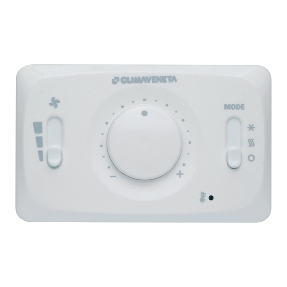
Manopola della temperatura
Temperature selector
La scelta della temperatura ambiente è
possibile regolando la posizione della
manopola alla temperatura desiderata
tra +14°C a +30°C.
Adjust the temperature as required by
turning the temperature selector from
+14°C to 30°C.
Led di segnalazione
Led description
Led blu acceso: Termostato fan-coil in
chiamata
Blue Led: indicates fan-coil thermostat
call
CONTENTS OF THE KIT
Description
MT electronic control with probes
Fastening bracket
Fastening screws
Instruction sheet
90% (non condensante) (not condensing)
90% (non condensante) (not condensing)
PC + ABS (autoestinguente V0) (flame retardant V0)
KIT COMANDO MT
MT CONTROL KIT
Selettore delle funzioni
Function selector
Raffreddamento
Cooling
Riscaldamento
Heating
Spegnimento
Off
Selettore della ventilazione
Fan selector
Velocità di ventilazione massima
Maximum fan speed
Velocità di ventilazione media
Medium fan speed
Velocità di cazione minima
Minimum fan speed
230 V ~ ±10%
50/60 Hz
2,5 A (cosØ ≥0.85; 230V)
NTC 10 kOhm @ T = 25 °C
NTC 10 kOhm @ T = 25 °C
+14°C a 30°C
-20 °C / +85 °C
0 °C / +55 °C
IP 30
RAL 9003 (bianco) (white)
120 x 75 x 25 mm
0,150 kg
Qty.
1
1
3
1
Advertisement

Subscribe to Our Youtube Channel
Related Manuals for CLIMAVENETA life2

Summary of Contents for CLIMAVENETA life2
- Page 1 KIT COMANDO MT MT CONTROL KIT Questo foglio istruzioni è parte integrante del libretto dell’apparec- These instructions are an integral part of the booklet accompanying chio sul quale è stato installato l’accessorio. A tale documento si the appliance on which the accessory is installed. Refer to this book- rimanda per le AVVERTENZE GENERALI.
- Page 2 DESCRIZIONE DELLE FUNZIONI DESCRIPTION OF FUNCTIONS Modalità di funzionamento ESTIVA SUMMER mode of operation La selezione della modalità Estiva avviene impostando il selettore della The Summer mode is selected by setting the mode selector on the rela- modalità in corrispondenza del simbolo tive symbol In questa modalità...
- Page 3 COMANDO DX COMANDO SX DX CONTROL SX CONTROL A = LIFE 102-202 B = LIFE 302-402 C = LIFE 502-602 D = LIFE 702-802 E = LIFE 902-1002 MORSETTIERA COLLEGAMENTO COMANDO TERMINAL BOARD TO BE CONNECTED TO THE CONTROL SONDA ACQUA DA POSIZIONARE WATER PROBE READY TO BE POSITIONED...
- Page 4 COLLEGAMENTI ELETTRICI - ELECTRICAL CONNECTIONS UNITA’ 2-TUBI: Eseguire questo collegamento sempre in caso di una sola valvola. 3 4 5 6 7 2-PIPES UNIT: Always carry out this connection Aria - Air when there is just one valve. Acqua - Water Valvola Valve 1 2 3 4 5 6 7...
Need help?
Do you have a question about the life2 and is the answer not in the manual?
Questions and answers