Table of Contents
Advertisement
Quick Links
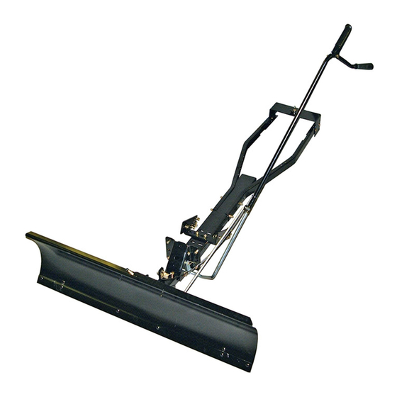
Owner's Manual
48" SNOW BLADE
Model No. 486.244283
CAUTION:
Before using this prod uct, read
this manual and fol low all Safe ty
Rules and Operating In struc tions.
Sears, Roebuck and Co., Hoffman Estates, IL 60179 U.S.A.
www.sears.com/craftsman
PRINTED IN U.S.A.
®
DO NOT RETURN TO STORE
For Missing Parts or Assembly
Questions Call 1-866-576-8388
Most fasteners are readily available
through any hardware store
STOP
• Safety
• Assembly
• Operation
• Maintenance
• Parts
FORM NO. 49828 (1/06)
Advertisement
Table of Contents

Related Manuals for Craftsman 486.244283


Summary of Contents for Craftsman 486.244283
- Page 1 Owner's Manual 48" SNOW BLADE Model No. 486.244283 CAUTION: Before using this prod uct, read this manual and fol low all Safe ty Rules and Operating In struc tions. Sears, Roebuck and Co., Hoffman Estates, IL 60179 U.S.A. www.sears.com/craftsman PRINTED IN U.S.A.
-
Page 2: Table Of Contents
3. Never allow children to operate tractor and snow blade, and do not allow adults to operate without proper instructions. 4. Always begin with transmission in fi rst (low) gear and gradually increase speed as required. MODEL NUMBER: SERIAL NUMBER: DATE OF PURCHASE: 486.244283 __________________ __________________... -
Page 3: Warranty
ACCESSORIES AND ATTACHMENTS These and other accessories are recommended for use with your unit. Call 1-800-4-MY-HOME® to fi nd out if they are available. If available, they may be purchased at most Craftsman outlets or by calling 1-800-4-MY-HOME®. WHEEL WEIGHT... -
Page 4: Full Size Hardware Chart
HARDWARE PACKAGE CONTENTS REF. REF. QTY. QTY. DESCRIPTION DESCRIPTION Hex Bolt, 1/4" x 3-1/4" LG. Hex Bolt, 1/4" x 3-1/4" LG. Hex Bolt, 1/4" x 3-1/4" LG. Hex Bolt 1/4" x 1-1/4" Hex Bolt 1/4" x 1-1/4" Hex Bolt 1/4" x 1-1/4" Hex Bolt, 5/16"... -
Page 5: Carton Contents
PARTS IN HARDWARE PACKAGES NOT SHOWN FULL SIZE REF. REF. REF. QTY. QTY. QTY. DESCRIPTION DESCRIPTION DESCRIPTION Cable End Fitting Cable End Fitting Cable End Fitting Cable Mount Bracket Cable Mount Bracket Cable Mount Bracket Angle Lock Spring Angle Lock Spring Angle Lock Spring Nylon Tie Nylon Tie... -
Page 6: Assembly
TOOLS REQUIRED FOR ASSEMBLY (1) Pliers (1) Hammer (1) Adjustable Wrench (or socket set) (1) 9/16" Open End or Box End Wrench (2) 7/16" Open End or Box End Wrench (2) 1/2" Open End or Box End Wrench REMOVAL OF PARTS FROM CARTON •... - Page 7 STEP 4: (SEE FIGURE 4) This step is for Sears tractors only. If you have a tractor brand other than Sears, skip to step 5. • Stack the short Hanger Bracket on top of the long Hanger Bracket with the ends of the brackets pointing up.
- Page 8 INSTRUCTIONS FOR TRACTORS WITH DUAL FRONT DECK SUSPENSION BRACKETS STEP 7: (SEE FIGURE 7) • Locate the Mower Deck Suspension Brackets on each side at the front of the tractor frame. A Sears tractor is shown below. For examples of brackets on other tractors see the illustrations on page 9.
- Page 9 SEARS TRACTORS WITH CENTER SUSPENSION BRACKET 12.75" LOCATE HANGER BRACKETS IN MIDDLE SET OF SLOTS IN THRUST CHANNEL SEARS LAWN TRACTORS 9.75" LOCATE HANGER BRACKETS IN MIDDLE SET OF SLOTS IN THRUST CHANNEL SEARS GARDEN TRACTORS 12" LOCATE HANGER BRACKETS IN MIDDLE SET OF SLOTS IN THRUST CHANNEL MTD - LAWN TRACTORS WITH FAST ATTACH FEATURE...
- Page 10 STEP 9: (SEE FIGURE 9) • Install the Rear Locating Bracket to the top of the Rear Mounting Bracket using two 3/8" x 1" Carriage bolts (H) and 3/8" nylock nuts (K). Tighten nuts. • Install the Rear Support Channels to the middle set of holes in the sides of the Rear Mounting Bracket using four 3/8"...
- Page 11 STEP 14: (SEE FIGURE 14) • Place the two angle lock bars together so that all holes are aligned. Assemble a 3/8" x 1-1/4" carriage bolt (G) and a 3/8" nylock nut (K) in the top hole. Be sure to insert bolt from side indicated.
- Page 12 STEP 18: (SEE FIGURE 18) • Assemble ball end of control cable up through hole in cable end fi tting and pull until ball slips inside curled edge of fi tting as shown. If ball won't slip under edge of curl it will need to be inserted through open end of curl.
-
Page 13: Assembly
STEP 21: (SEE FIGURE 21) • From the left side, insert the welded end of the lift handle rod through the exposed holes in the end of the channel assembly. Next, insert the lift link pin through the hole in the bracket that is welded to the lift handle rod. - Page 14 KNOW YOUR SNOW BLADE Read this owner's manual and safety rules before operating your snowblade. Compare the illustration below with your snow blade to familiarize yourself with the various controls and their locations. ANGLE LOCK BARS BLADE ADJUST SPRING BLADE SHOE BLADE PIVOT SHAFT LOCK RELEASE GRIP ASS'Y.
-
Page 15: Maintenance
Using the Snowblade Wheel weights and tire chains must be used with your snow blade for traction. These accessories are available at your nearest Sears retail store. See page 3. • Prepare the lawn tractor engine for cold weather using instructions furnished with the lawn tractor. -
Page 16: Service And Adjustments
To Adjust Blade Spring • The tension of the blade adjust spring may be altered to permit the blade to tilt forward to bypass solid obstructions. To change the spring tension, adjust the nuts at upper end of the spring bolt. Turn the nuts counterclockwise to relieve tension and clockwise to increase tension. - Page 17 NOTES...
-
Page 18: Repair Parts Illustration
PARTS REPAIR PARTS LIST FOR MODEL 486.244283 - 48" SNOW BLADE... -
Page 19: Repair Parts List
REPAIR PARTS LIST FOR MODEL 486.244283 - 48" SNOW BLADE... - Page 20 Get it fixed, at your home or ours! For repair – in your home – of all major brand appliances, lawn and garden equipment, or heating and cooling systems, no matter who made it, no matter who sold it! For the replacement parts, accessories and owner’s manuals that you need to do-it-yourself.