
Related Manuals for TASKING iSYSTEM ARM HSSTP II


Summary of Contents for TASKING iSYSTEM ARM HSSTP II
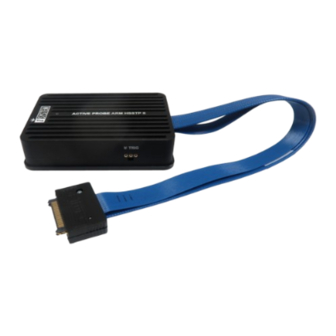
- Page 1 ARM HSSTP II Active Probe Hardware User Manual V2.6, November 2023 isystem.com/start...
- Page 2 General safety instructions Please read the following safety precautions carefully before putting this device to use to avoid any personal injuries, damage to the instrument, or to the target system. Use this instrument only for its intended purpose as specified by this manual to prevent potential hazards. Use included power cord and power supply The enclosed power supply has been approved for use by iSYSTEM.
-
Page 3: Table Of Contents
Contents Package content ..........................4 Specifications ............................5 Operation ............................... 6 mDIO Cable ..............................8 40-pin Samtec ERF8 to 20-pin 2.54mm ARM Converter ............... 9 40-pin Samtec ERF8 to 10-pin 1.27mm CoreSight and 40-pin Samtec ERF8 HSSTP Converter ..............................10 10-pin 1.27mm CoreSight to 20-pin 2.54mm ARM Converter ............ -
Page 4: Package Content
Package content Active Probe ARM HSSTP II allows debugging, tracing and testing ARM® Cortex™ architectures. It supports both the JTAG debug interface and ARM High-Speed Trace Port (HSSTP). Its small and compact hardware size allows for connecting to a target microcontroller in a confined space as far as 10 m away. -
Page 5: Specifications
Specifications GENERAL Supply voltage 9.0V DC via FNet cable Operating temperature 10°C to 40°C Storage temperature -10°C to 60°C Humidity 5% to 80% RH MECHANICAL Size 80 x 55 x 18 mm Weight 0.125 kg Cable length 23 cm OPERATION Communication inter- iSYSTEM proprietary FNet face to BlueBox... -
Page 6: Operation
Operation A – 40-pin HSSTP connector with 20cm high-speed cable and the following pinout: Signal Direc- Signal Direc- Signal Description Signal Signal Signal Description tion tion HSSTP Lane 4 Tx4_P Vref Reference Voltage HSSTP Lane 4 Tx4_N TCK/SWCLK JTAG / SWD Ground Ground HSSTP Lane 2... - Page 7 Number Name Pin1 IOØ Pin2 Pin3 mDIO port on the Active Probe mDIO port pinout C – The indicator light provides the status of the Active Probe as follows: Permanently green – Powered on and ready to use. Blinking green – Establishing connection with the BlueBox. Blinking blue –...
-
Page 8: Mdio Cable
mDIO Cable Ordering code BB-AP-MDIO-20 mDIO Cable is used to connect the Active Probe mDIO port with the signals around the de- bugged microcontroller, which can then be either read or controlled by the debugger. For ex- ample, the debugger can periodically service an external watchdog through the mDIO output or just read and record an external signal through the mDIO input. -
Page 9: 40-Pin Samtec Erf8 To 20-Pin 2.54Mm Arm Converter
40-pin Samtec ERF8 to 20-pin 2.54mm ARM Converter Ordering code IASAM40ARMPIN20 In conjunction with this 40-pin Samtec ERF8 to 20-pin 2.54 ARM converter delivered in the pack- age, the Active Probe can be connected to the target board featuring a 20-pin 2.54 mm ARM tar- get debug connector providing the JTAG debug interface. -
Page 10: 40-Pin Samtec Erf8 To 10-Pin 1.27Mm Coresight And 40-Pin Samtec Erf8 Hsstp Converter
40-pin Samtec ERF8 to 10-pin 1.27mm CoreSight and 40-pin Samtec ERF8 HSSTP Converter Ordering code IASAM40HSSTP-JTAGSAM Normally 40-pin ERF8 ARM HSSTP connector provides both, ARM HHSTP trace interface and JTAG or SWD debug interface. However, some targets for some reason don’t connect debug in- terface to this connector and provide the debug JTAG/SWD interface on a separate debug con- nector (10-pin 1.27mm CoreSight). - Page 11 The converter has the following pinouts: A – 40-pin Samtec ERF8 connector providing merged JTAG/SWD debug signals (C on the im- age) and the HSSTP trace signals (B on the image) signals, to which the Active Probe connects then. Signal Direc- Signal Descrip- Signal De- Signal Direc-...
- Page 12 B – 40-pin Samtec ERF8 connector which connects to target development board with 40-pin Samtec ERF8 connector exposing only the HSSTP trace signals. Signal Direc- Signal Descrip- Signal De- Signal Direc- Signal Signal tion tion scription tion Reference HSSTP Lane 4 Tx4_P Vref Voltage...
-
Page 13: 10-Pin 1.27Mm Coresight To 20-Pin 2.54Mm Arm Converter
10-pin 1.27mm CoreSight to 20-pin 2.54mm ARM Converter Related to the just described converter IASAM40HSSTP-JTAGSAM, the target development board can also feature a 20-pin 2.54 mm ARM target debug connector instead of the 10-pin 1.27 mm CoreSight. To connect the C part of the IASAM40HSSTP-JTAGSAM to this connector, another converter IA10PINCS20PINARM-1 is required, converting from ARM 20-pin 2.54mm to 10-pin 1.27 CoreSight. -
Page 14: 40-Pin Samtec / Usb-C To Usb-C (Hsstp) Switch
40-pin Samtec / USB-C to USB-C (HSSTP) Switch Ordering code IEA-SWITCH-SAM40USBC Through this hardware switch, you can conveniently connect: · ARM HSSTP II Active Probe · and a host PC via a standard USB-C connection to NVIDIA Orin device (connection marked as ORIN USB-C) at the same time. This switch is op- tional and must be ordered separately. - Page 15 Switch configuration MODE SELECT jumper defines which connection is active. MODE SELECT SWITCH MODE in- Selected Description jumper dication USB-C connection between the PC and Not populated / The HOST LED is HOST USB-C the NVIDIA Orin device is established. not bridged.
- Page 16 Signal Dir- Signal Dir- Signal Description Signal Signal Signal Description ection ection USB +5V Supply VBUS VBUS USB +5V Supply USB 3.0 SSRX RX2_N TX2_N USB 3.0 SSTX USB 3.0 SSRX RX2_P TX2_P USB 3.0 SSTX Ground Ground ORIN USB-C pinout in HOST mode...
- Page 17 The following pinout is valid on ORIN USB-C connector in HSSTP mode: Signal Dir- Signal Dir- Signal Description Signal Signal Signal Description ection ection Ground Ground HSSTP Lane 0 TX0_P Not Connected HSSTP Lane 0 TX0_N Not Connected Reference Voltage VREF VREF Reference Voltage...
-
Page 18: Hardware Setup And Configuration
Hardware Setup and Configuration For detailed visual presentation of the hardware setup and configuration, refer to Get- ting started tutorial - use the link isystem.com/start. 1. Connect the power supply cable. BlueBox should be switched off. 2. First connect the BlueBox to the PC via USB cable. Later you can configure TCP/IP connection to work remotely. -
Page 19: Accessories
Accessories Analog/Digital and Network Trace Description Ordering Code IOM6 Hub (3 x FNet & FBridge) IC57031 IOM6 CAN/LIN IC57040 IOM6 ADIO IC57041 ARM HSSTP II Active Probe IC57125-1 Infineon DAP/DAPE II Active Probe IC57163-1 Infineon AGBT Active Probe IC57164 MPC5x/SPC5x Aurora Active Probe IC57150 Infineon SGBT (HSTCU) Active Probe IC57166... - Page 20 Visit our website for: · Support - isystem.com/support · Tutorials - isystem.com/start · Knowledge Base - kb.isystem.com www.isystem.com...
Need help?
Do you have a question about the iSYSTEM ARM HSSTP II and is the answer not in the manual?
Questions and answers