GIGABYTE X670E AORUS MASTER - Motherboard Manual
- User manual (46 pages) ,
- User manual
Advertisement
- 1 Identifying Your Motherboard Revision
- 2 Product Introduction
- 3 Hardware Installation
- 4 BIOS Setup
- 5 Installing the Operating System and Drivers
- 6 Configuring a RAID Set
- 7 Debug LED Codes
- 8 Documents / Resources
Identifying Your Motherboard Revision
The revision number on your motherboard looks like this: "REV: X.X." For example, "REV: 1.0" means the revision of the motherboard is 1.0. Check your motherboard revision before updating motherboard BIOS, drivers, or when looking for technical information.
Example:

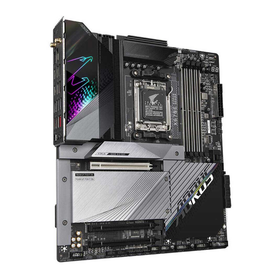
Product Introduction
Motherboard Layout

(Note)
For debug code information, please refer to the Debug LED Codes chapter.
Motherboard Block Diagram

(Note) Actual support may vary by CPU.
Hardware Installation
Installation Precautions
The motherboard contains numerous delicate electronic circuits and components which can become damaged as a result of electrostatic discharge (ESD). Prior to installation, carefully read the user's manual and follow these procedures:
- Prior to installation, make sure the chassis is suitable for the motherboard.
- Prior to installation, do not remove or break motherboard S/N (Serial Number) sticker or warranty sticker provided by your dealer. These stickers are required for warranty validation.
- Always remove the AC power by unplugging the power cord from the power outlet before installing or removing the motherboard or other hardware components.
- When connecting hardware components to the internal connectors on the motherboard, make sure they are connected tightly and securely.
- When handling the motherboard, avoid touching any metal leads or connectors.
- It is best to wear an electrostatic discharge (ESD) wrist strap when handling electronic components such as a motherboard, CPU or memory. If you do not have an ESD wrist strap, keep your hands dry and first touch a metal object to eliminate static electricity.
- Prior to installing the motherboard, please have it on top of an antistatic pad or within an electrostatic shielding container.
- Before connecting or unplugging the power supply cable from the motherboard, make sure the power supply has been turned off.
- Before turning on the power, make sure the power supply voltage has been set according to the local voltage standard.
- Before using the product, please verify that all cables and power connectors of your hardware components are connected.
- To prevent damage to the motherboard, do not allow screws to come in contact with the motherboard circuit or its components.
- Make sure there are no leftover screws or metal components placed on the motherboard or within the computer casing.
- Do not place the computer system on an uneven surface.
- Do not place the computer system in a high-temperature or wet environment.
- Turning on the computer power during the installation process can lead to damage to system components as well as physical harm to the user.
- If you are uncertain about any installation steps or have a problem related to the use of the product, please consult a certified computer technician.
- If you use an adapter, extension power cable, or power strip, ensure to consult with its installation and/or grounding instructions.
Product Specifications
| CPU |
|
| Chipset |
|
| Memory |
|
| Onboard Graphics |
|
| Audio |
|
| LAN |
|
| Wireless Communication Module |
|
| Expansion Slots |
|
| Storage Interface |
|
| USB |
|
| Internal Connectors |
|
| Internal Connectors |
|
| Back Panel Connectors |
|
| I/O Controller |
|
| Hardware Monitor |
|
| BIOS |
|
| Unique Features |
|
| Bundled Software |
|
| Operating System |
|
| Form Factor |
|
* GIGABYTE reserves the right to make any changes to the product specifications and product-related information without prior notice![]()
![]() Please visit the SERVICE/SUPPORT\Utility page on GIGABYTE's website to download the latest version of apps.
Please visit the SERVICE/SUPPORT\Utility page on GIGABYTE's website to download the latest version of apps.
https://www.gigabyte.com/Support/Utility/Motherboard?m=ut
CPU and CPU Cooler
Read the following guidelines before you begin to install the CPU:
![warning]()
Make sure that the motherboard supports the CPU. (Go to GIGABYTE's website for the latest CPU support list.)- Always turn off the computer and unplug the power cord from the power outlet before installing the CPU to prevent hardware damage.
- Locate the pin one of the CPU. The CPU cannot be inserted if oriented incorrectly. (Or you may locate the notches on both sides of the CPU and alignment keys on the CPU socket.)
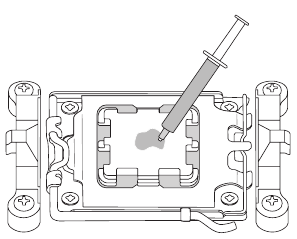
- Apply an even and thin layer of thermal grease on the surface of the CPU.
- Do not turn on the computer if the CPU cooler is not installed, otherwise overheating and damage of the CPU may occur.
- Set the CPU host frequency in accordance with the CPU specifications. It is not recommended that the system bus frequency be set beyond hardware specifications since it does not meet the standard requirements for the peripherals. If you wish to set the frequency beyond the standard specifications, please do so according to your hardware specifications including the CPU, graphics card, memory, hard drive, etc.
Note the CPU Orientation
Note the alignment keys on the motherboard CPU socket and the notches on the CPU.


Do not remove the CPU socket cover before inserting the CPU. It may pop off from the load plate automatically after you insert the CPU and close the load plate.
CPU
Follow the steps below to correctly install the CPU into the motherboard CPU socket.
-
- Gently press the CPU socket lever handle down and away from the socket
![]()
- Completely lift up the CPU socket locking lever.
- With your fingers, hold the plastic protective cover attached to the metal load plate to lift open the metal load plate.

- Gently press the CPU socket lever handle down and away from the socket
- Hold the CPU with your fingers by the edges. Align the CPU pin one marking (triangle) with the pin one corner of the CPU socket (or you may align the CPU notches with the socket alignment keys) and gently insert the CPU into position.

- Make sure the CPU is properly installed and then close the load plate. Secure the socket lever under its retention tab The plastic protective cover will pop off by itself and can be removed.
* Always replace the plastic protective cover when the CPU is not installed to protect the CPU socket.


Do not force to engage the CPU socket locking lever when the CPU is not installed correctly as this would damage the CPU and CPU socket.
CPU Cooler
Be sure to install the CPU cooler after installing the CPU. (Actual installation process may differ depending the CPU cooler to be used. Refer to the user's manual for your CPU cooler.)
- Apply an even and thin layer of thermal grease on the surface of the installed CPU
![]()
![]()
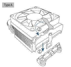
- 121/Type A
![]()
Hook the CPU cooler clip to the mounting lug on one side of the retention frame. On the other side, push straight down on the CPU cooler clip to hook it to the mounting lug on the retention frame. Turn the cam handle from the left side to the right side to lock into place.
![]()
Type B![]()
First remove the four screws from the CPU retention frame and remove the CPU retention frame. Then align the four shoulder screws on the CPU cooler with the standoffs from the back plate. Fasten each shoulder screw in a 1-2-3-4 (x) pattern as shown on the right.

![]()
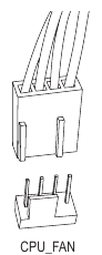
* When using a Type B CPU cooler, it is not recommended to fasten each screw down all the way in one step. Follow order 1-2-34, fasten screw clockwise 1 rotation per step. Repeat steps 1-2-3-4 till all screws are fastened. - Finally, attach the power connector of the CPU cooler to the CPU fan header (CPU FAN) on the motherboard
![]()
![]()


Installing the Memory
Read the following guidelines before you begin to install the memory:
![warning]()
Make sure that the motherboard supports the memory. It is recommended that memory of the same capacity, brand, speed, and chips be used. (Go to GIGABYTE's website for the latest supported memory speeds and memory modules.)- Always turn off the computer and unplug the power cord from the power outlet before installing the memory to prevent hardware damage.
- Memory modules have a foolproof design. A memory module can be installed in only one direction. If you are unable to insert the memory, switch the direction.
Dual Channel Memory Configuration
This motherboard provides four memory sockets and supports Dual Channel Technology. After the memory is installed, the BIOS will automatically detect the specifications and capacity of the memory. Enabling Dual Channel memory mode will double the original memory bandwidth.
The four memory sockets are divided into two channels and each channel has two memory sockets as following:
 Channel A: DDR5 Al, DDR5 A2
Channel B: DDR5 Bl, DDR5 B2
* Recommended Dual Channel Memory Configuration![]()
| DDR5_A1 | DDR5_A2 | DDR5_B1 | DDR5_B2 | |
| 2 Modules | - - | DS/SS | - - | DS/SS |
| 4 Modules | DS/SS | DS/SS | DS/SS | DS/SS |
(SS-Single-Sided, DS=Double-Sided, "- -"=No Memory)
Due to CPU limitations, read the following guidelines before installing the memory in Dual Channel mode.
- Dual Channel mode cannot be enabled if only one memory module is installed.
- When enabling Dual Channel mode with two or four memory modules, it is recommended that memory of the same capacity, brand, speed, and chips be used.


When installing a single memory module, we recommend that you install it in the DDR5 A2 or DDR5 B2 socket.
Installing an Expansion Card
Read the following guidelines before you begin to install an expansion card:
![warning]()
Make sure the motherboard supports the expansion card. Carefully read the manual that came with your expansion card.- Always turn off the computer and unplug the power cord from the power outlet before installing an expansion card to prevent hardware damage.
Follow the steps below to correctly install your expansion card in the expansion slot.
- Locate an expansion slot that supports your card. Remove the metal slot cover from the chassis back panel.
- Align the card with the slot, and press down on the card until it is fully seated in the slot.
- Make sure that the expansion card is fully seated in its slot.
- Secure the card's metal bracket to the chassis back panel with a screw.
- After installing all expansion cards, replace the chassis cover(s).
- Turn on your computer. If necessary, go to BIOS Setup to make any required BIOS changes for your expansion card(s).
- Install the driver provided with the expansion card in your operating system.


![]() Please visit GIGABYTE's website for details on using PCIe EZ-Latch Plus. https://www.gigabyte.com/WebPage/922/removePClE.html
Please visit GIGABYTE's website for details on using PCIe EZ-Latch Plus. https://www.gigabyte.com/WebPage/922/removePClE.html
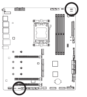
Back Panel Connectors

- Q-Flash Plus Button (Note)
Q-Flash Plus allows you to update the BIOS when your system is off (S5 shutdown state). Save the latest BIOS on a USB thumb drive and plug it into the dedicated port, and then you can now flash the BIOS automatically by simply pressing the Q-Flash Plus button. The QFLED will flash when the BIOS matching and flashing activities start and will stop flashing when the main BIOS flashing is complete. - SMA Antenna Connectors (2TR2)
Use this connector to connect an antenna.
![]()
Tighten the antennas to the antenna connectors and then aim the antennas correctly for better signal reception. - DisplayPort
DisplayPort delivers high quality digital imaging and audio, supporting bi-directional audio transmission. You can use this port to connect your DisplayPort-supported monitor. Note: The DisplayPort Technology can support a maximum resolution of 3840x2160@144 Hz but the actual resolutions supported depend on the monitor being used. - HDMI Port
![]()
The HDMI port is HDCP 2.3 compliant and supports Dolby TrueHD and DTS HD HIGH-DEFINITION MULTIMEDIA INTERFACE Master Audio formats. It also supports up to 192KHz/24bit 7. I-channel LPCM audio output. You can use this port to connect your HDMl-supported monitor. The maximum supported resolution is 4096x2160@60 Hz, but the actual resolutions supported are dependent on the monitor being used.
![]()
After installing the DisplayPort/HDMl device, make sure to set the default sound playback device to DisplayPort/HDMl. (The item name may differ depending on your operating system.) - USB 2.0/1.1 Port
The USB port supports the USB 2.0/1.1 specification. Use this port for USB devices. - USB Type-C@ Port (with USB 3.2 Gen 2 Support) (DisplayPort)
This port supports standard USB Type-C and DisplayPort display output. You can connect a USB Type-C monitor to this port or use an adapter cable to connect a standard DisplayPort monitor. The maximum supported resolution is 3840x2160@144 Hz when using a DisplayPort monitor, but the actual resolutions supported are dependent on the monitor being used. Also, the connector is reversible and supports the USB 3.2 Gen 2 specification and is compatible to the USB 3.2 Gen 1 and USB 2.0 specification. You can use this port for USB devices, too.


![warning]()
When removing the cable connected to a back panel connector, first remove the cable from your device and then remove it from the motherboard.- When removing the cable, pull it straight out from the connector. Do not rock it side to side to prevent an electrical short inside the cable connector.
- USB 3.2 Gen 2 Type-A Port (Red)
The USB 3.2 Gen 2 port supports the USB 3.2 Gen 2 specification and is compatible to the USB 3.2 Gen 1 and USB 2.0 specification. Use this port for USB devices. - USB 3.2 Gen 2 Type-A Port (Red) (Q-Flash Plus Port)
The USB 3.2 Gen 2 port supports the USB 3.2 Gen 2 specification and is compatible to the USB 3.2 Gen 1 and USB 2.0 specification. Use this port for USB devices. Before using Q-Flash Plus (Note), make sure to insert the USB flash drive into this port first. - USB Type-C@ Port (with USB 3.2 Gen 2x2 Support)
The reversible USB port supports the USB 3.2 Gen 2x2 specification and is compatible to the USB 3.2 Gen 2, USB 3.2 Gen 1, and USB 2.0 specifications. Use this port for USB devices. - USB 3.2 Gen 1 Port
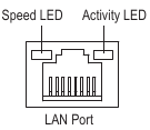
The USB 3.2 Gen 1 port supports the USB 3.2 Gen 1 specification and is compatible to the USB 2.0 specification. Use this port for USB devices. - RJ45 LAN Port
The Gigabit Ethernet LAN port provides Internet connection at up to 2.5 Gbps data rate. The following describes the states of the LAN port LEDs.
![]()
Speed LED:State Description Green 2.5 Gbps data rate Orange 1 Gbps data rate Off 100 Mbps data rate Activity LED:
State Description Blinking Data transmission or receiving is occurring On No data transmission or receiving is occurring - Line Out/Front Speaker Out
The line out jack. - Mic In/Rear Speaker Out
The Mic in jack. - Optical SIPDIF Out Connector
This connector provides digital audio out to an external audio system that supports digital optical audio. Before using this feature, ensure that your audio system provides an optical digital audio in connector.
Audio Jack Configurations:
| Jack | Headphone/ 2-channel | 4-channel | 5.1-channel | 7.1-channel |
|  | | | |
 |
| Front Panel Line Out/ Side Speaker Out | | |||
| Front Panel Mic In/Center/ Subwoofer Speaker Out | | |
 You can change the functionality of an audio jack using the audio software. To configure 7.1 -channel audio, access the audio software for audio settings.
![]() Please visit GIGABYTE's website for details on configuring the audio software.
Please visit GIGABYTE's website for details on configuring the audio software.
https://www.gigabyte.com/WebPage/698/realtek1220-audio.html
(Note)
To enable the Q-Flash Plus function, please navigate to the "Unique Features" page of GIGABYTE's website for more information.
Onboard Buttons, Voltage Measurement Points and LEDs
Quick Buttons
This motherboard has 2 quick buttons: power button and reset button. The power button and reset button allow users to quickly turn on/off or reset the computer in an open-case environment when they want to change hardware components or conduct hardware testing.

PW SW: Power Button
RST SW: Reset Button

The reset button provides you with several functions to use. To remap the button to perform different tasks, please navigate to the "BIOS Setup" page of GIGABYTE's website and search for "RST_SW (MULTIKEY)" for more information.
Voltage Measurement Points
Use a multimeter to measure the following motherboard voltages.

Status LEDs
The status LEDs show whether the CPU, memory, graphics card, and operating system are working properly after system power-on. If the CPU/DRAMNGA LED is on, that means the corresponding device is not working normally; if the BOOT LED is on, that means you havent entered the operating system yet.

CPU: CPU status LED
DRAM: Memory status LED
VGA: Graphics card status LED
BOOT: Operating system status LED
Internal Connectors

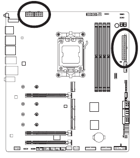
- ATX_12V/ATX_12V1
- ATX
- CPU_FAN
- SYS_FAN1/2/3/4
- SYS_FAN5/6/7/8_PUMP
- CPU_OPT
- EC_TEMP1/EC_TEMP2
- D_LED1/D_LED2
- LED_CPU
- LED_C1/LED_C2
- SATA3 0/1/2/3/4/5
- M2A_CPU/M2B_CPU/M2C_SB/M2D_SB
- F_PANEL
- F_AUDIO
- F_U320G
- F_U32_1/F_U32_2
- F_USB1/F_USB2
- SPI_TPM
- THB_U4
- NOISE_SENSOR
- RST
- CLR_CMOS
- BAT
Read the following guidelines before connecting external devices:
![warning]()
First make sure your devices are compliant with the connectors you wish to connect.- Before installing the devices, be sure to turn off the devices and your computer. Unplug the power cord from the power outlet to prevent damage to the devices.
- After installing the device and before turning on the computer, make sure the device cable has been securely attached to the connector on the motherboard.
ATX 12V/ATX 12V1/ATX 12V (2x4 Power Connectors and Main Power Connector)
With the use of the power connector, the power supply can supply enough stable power to all the components on the motherboard. Before connecting the power connector, first make sure the power supply is turned off and all devices are properly installed. The power connector possesses a foolproof design. Connect the power supply cable to the power connector in the correct orientation.
The 12V power connector mainly supplies power to the CPU. If the 12V power connector is not connected, the computer will not start.
 To meet expansion requirements, it is recommended that a power supply that can withstand high power consumption be used (500W or greater). If a power supply is used that does not provide the required power, the result can lead to an unstable or unbootable system.
ATX_12V/ATX_12V1:
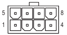
| Pin No. | Definition |
| 1 | GND (Only for 2x4-pin 12V) |
| 2 | GND (Only for 2x4-pin 12V) |
| 3 | GND |
| 4 | GND |
| 5 | +12V (Only for 2x4-pin 12V) |
| 6 | +12V (Only for 2x4-pin 12V) |
| 7 | +12V |
| 8 | +12V |
ATX:
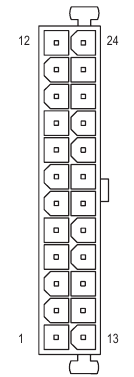
| Pin No. | Definition | Pin No. | Definition |
| 1 | 3.3V | 13 | 3.3V |
| 2 | 3.3V | 14 | -12V |
| 3 | GND | 15 | GND |
| 4 | +5V | 16 | PS_ON (soft On/Off) |
| 5 | GND | 17 | GND |
| 6 | +5V | 18 | GND |
| 7 | GND | 19 | GND |
| 8 | Power Good | 20 | NC |
| 9 | 5VSB (stand by +5V) | 21 | +5V |
| 10 | +12V | 22 | +5V |
| 11 | +12V (Only for 2x12-pin ATX) | 23 | +5V (Only for 2x12-pin ATX) |
| 12 | 3.3V (Only for 2x12-pin ATX) | 24 | GND (Only for 2x12-pin ATX) |
CPU FAN/SYS FAN1/2/3/4 (Fan Headers)
All fan headers on this motherboard are 4-pin. Most fan headers possess a foolproof insertion design. When connecting a fan cable, be sure to connect it in the correct orientation (the black connector wire is the ground wire). The speed control function requires the use of a fan with fan speed control design. For optimum heat dissipation, it is recommended that a system fan be installed inside the chassis.

CPU_FAN

SYS_FAN1/SYS_FAN2/ SYS_FAN3

SYS_FAN4
| Pin No. | Definition |
| 1 | GND |
| 2 | Voltage Speed Control |
| 3 | Sense |
| 4 | PWM Speed Control |
SYS FAN5/6/7/8_PUMP (System Fan/Water Cooling Pump Headers)
The fan/pump headers are 4-pin. Most fan headers possess a foolproof insertion design. When connecting a fan cable, be sure to connect it in the correct orientation (the black connector wire is the ground wire). The speed control function requires the use of a fan with fan speed control design. For optimum heat dissipation, it is recommended that a system fan be installed inside the chassis. The header also provides speed control for a water cooling pump. Please navigate to the "BIOS Setup" page of GIGABYTE's website and search for "Smart Fan 6" for more information.

SYS FAN5 PUMP
 SYS FAN6 PUMP/SYS FAN7 PUMP

SYS FAN8 PUMP
| Pin No. | Definition |
| 1 | GND |
| 2 | Voltage Speed Control |
| 3 | Sense |
| 4 | PWM Speed Control |
![warning]()
Be sure to connect fan cables to the fan headers to prevent your CPU and system from overheating. Overheating may result in damage to the CPU or the system may hang.- These fan headers are not configuration jumper blocks. Do not place ajumper cap on the headers.
CPU_OPT (CPU Fan/Water Cooling Pump Header)
The fan/pump header is 4-pin and possesses a foolproof insertion design. Most fan headers possess a foolproof insertion design. When connecting a fan cable, be sure to connect it in the correct orientation (the black connector wire is the ground wire). The speed control function requires the use of a fan with fan speed control design.
| Pin No. | Definition |
| 1 | GND |
| 2 | Voltage Speed Control |
| 3 | Sense |
| 4 | PWM Speed Control |

| Connector | CPU_FAN | SYS_FAN1~4 | SYS_FAN5~8_PUMP | CPU_OPT |
| Maximum Current | 2A | 2A | 2A | 2A |
| Maximum Power | 24W | 24W | 24W | 24W |
EC TEMPI/EC TEMP2 (Temperature Sensor Headers)
Connect the thermistor cables to the headers for temperature detection.

| Pin No. | Definition |
| 1 | SENSOR IN |
| 2 | GND |
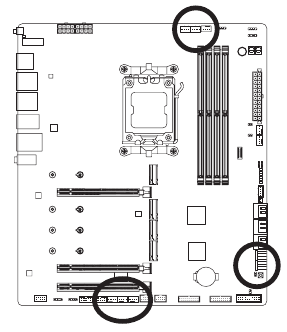
D LEDI/D LED2 (Addressable LED strip Headers)
The headers can be used to connect a standard 5050 addressable LED strip, with maximum power rating of 5A (5V) and maximum number of 1000 LEDs.

| Pin No. | Definition |
| 1 | V (5V) |
| 2 | Data |
| 3 | No Pin |
| 4 | GND |
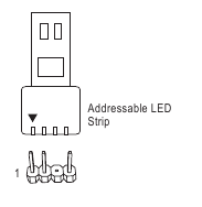
Connect your addressable LED strip to the header. The power pin (marked with a triangle on the plug) of the LED strip must be connected to Pin 1 of the addressable LED strip header. Incorrect connection may lead to the damage of the LED strip.
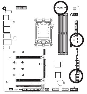
LED CPU (CPU Cooler LED Strip/RGB LED strip Header)
The header can be used to connect a CPU cooler LED strip or a standard 5050 RGB LED strip (12V/G/R/B), with maximum power rating of 2A (12V) and maximum length of 2m.

| Pin No. | Definition |
| 1 | 12V |
| 2 | G |
| 3 | R |
| 4 | B |
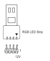
Connect the CPU cooler LED strip/RGB LED strip to the header. The powerRGB LED strip pin (marked with a triangle on the plug) of the LED strip must be connected to Pin 1 (12V) of this header. Incorrect connection may lead to the damage of the LED strip.

For how to turn on/off the lights of the LED strip, please navigate to the "Unique Features" page of GIGABYTE's website.
Before or removing installing the devices, be sure to turn off the devices and your computer. Unplug the power cord from the power outlet to prevent damage to the devices.
LED CllLED C2 (RGB LED strip Headers)
The headers can be used to connect a standard 5050 RGB LED strip (12V/G/R/B), with maximum power rating of 2A (12V) and maximum length of 2m.

LED_C2

LED_C1
| Pin No. | Definition |
| 1 | 12V |
| 2 | G |
| 3 | R |
| 4 | B |
Connect one end of the RGB LED strip extension cable to the header and the other end to your RGB LED strip. The black wire (marked with a triangle on theRGB LED plug) of the extension cable must be connected to Pin 1 (12V) of this header. TheStrip 12V pin (marked with an arrow) on the other end of the extension cable must be lined up with the 12V of the LED strip. Be careful with the connection orientation of the LED strip; incorrect connection may lead to the damage of the LED strip.

For how to turn on/off the lights of the LED strip, please navigate to the "Unique Features" page of GIGABYTE's website.
Before or removing installing the devices, be sure to turn off the devices and your computer. Unplug the power cord from the power outlet to prevent damage to the devices.
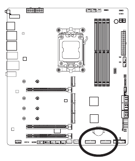
SATA3 01112131415 (SATA 6Gb/s Connectors)
The SATA connectors conform to SATA 6Gb/s standard and are compatible with SATA 3Gb/s and SATA 1.5Gb/s standard. Each SATA connector supports a single SATA device. The SATA connectors support RAID O, RAID l, and RAID 10. Please navigate to the "Configuring a RAID Set" page of GIGABYTE's website for instructions on configuring a RAID array.

| Pin No. | Definition |
| 1 | GND |
| 2 | TXP |
| 3 | TXN |
| 4 | GND |
| 5 | RXN |
| 6 | RXP |
| 7 | GND |

To enable hot-plugging for the SATA ports, please navigate to the "BIOS Setup" page of GIGABYTE's website and search for "SATA Configuration" for more information.
M2A CPU/M2B CPU/M2C SBIM2D SB (M.2 Socket 3 Connectors)
There are two types of M.2 SSDs: M.2 SATA SSDs and M.2 PCIe SSDs. This motherboard only supports M.2 PCIe SSDs. Please note that an M.2 PCIe SSD cannot be used to create a RAID set with a SATA hard drive. Please navigate to the "Configuring a RAID Set' page of GIGABYTE's website for instructions on configuring a RAID array.

Follow the steps below to correctly install an M.2 SSD in the M.2 connector.
Step 1:
To access the M.2 slot you want to use, unfasten the screws on the motherboard heatsink diagonally to remove the heatsink. Locate the proper mounting hole for the M.2 SSD to be installed and then install the M.2 EZ-Latch Plus clip first.
If you want install an M.2 SSD in the 11 Omm hole that already has a motherboard heatsink standoff, be sure to remove the EZ-Latch Plus clip first and use the motherboard heatsink screw to secure the heatsink and SSD.
Step 2:
Remove the protective film from the thermal pad on the M.2 connector. Insert the M.2 SSD into the M.2 connector at an angle.
Step 3:
Press down on the front end of the M.2 SSD and make sure the M.2 SSD is secured by the M.2 EZ-Latch Plus clip. Remove the protective film from the thermal pad at the bottom of the motherboard heatsink and then replace the heatsink and tighten the screws diagonally.
* Types of M.2 SSDs supported by each M.2 connector:
| M.2 PCIe x4 SSD | M.2 PCIe x2 SSD | M.2 SATA SSD | |
| M2A_CPU |  | |  |
| M2B_CPU | | | |
| M2C_SB | | | |
| M2D_SB | | | |
![]() Please visit GIGABYTE's website for details on using M.2 EZ-Latch Plus.
Please visit GIGABYTE's website for details on using M.2 EZ-Latch Plus.
Install the M 2 SSD https://www.gigabyte.com/WebPage/920/M2-latchplus.html
Remove the M 2 SSD https://www.gigabyte.com/WebPage/921/removeM2.html
* Motherboard heatsink design may vary by model.
F PANEL (Front Panel Header)
Connect the power switch, reset switch, speaker, chassis intrusion switch/sensor and system status indicator on the chassis to this header according to the pin assignments below. Note the positive and negative pins before connecting the cables.
")
- PLED/PWR_LED (Power LED):
Connects to the power status indicator on the chassis front panel. The LED is on when the system is operating. The LED is off when the system is in S3/ S4 sleep state or powered off (S5).
| System Status | LED |
| S0 | On |
| S3/S4/S5 | Off |
- PW (Power Switch):
Connects to the power switch on the chassis front panel. You may configure the way to turn off your system using the power switch (please navigate to the "BIOS Setup" page of GIGABYTE's website and search for "Soft-Off by PWR-BTTN" for more information). - SPEAK (Speaker):
Connects to the speaker on the chassis front panel. The system reports system startup status by issuing a beep code. One single short beep will be heard if no problem is detected at system startup. - HD (Hard Drive Activity LED):
Connects to the hard drive activity LED on the chassis front panel. The LED is on when the hard drive is reading or writing data. - RES (Reset Switch):
Connects to the reset switch on the chassis front panel. Press the reset switch to restart the computer if the computer freezes and fails to perform a normal restart. - CI (Chassis Intrusion Header):
Connects to the chassis intrusion switch/sensor on the chassis that can detect if the chassis cover has been removed. This function requires a chassis with a chassis intrusion switch/sensor. - NC: No connection.
The front panel design may differ by chassis. A front panel module mainly consists of power switch, reset switch, power LED, hard drive activity LED, speaker and etc. When connecting your chassis front panel module to this header, make sure the wire assignments and the pin assignments are matched correctly.
F_AUDIO (Front Panel Audio Header)
The front panel audio header supports High Definition audio (HD). You may connect your chassis front panel audio module to this header. Make sure the wire assignments of the module connector match the pin assignments of the motherboard header. Incorrect connection between the module connector and the motherboard header will make the device unable to work or even damage it.
")
| Pin No. | Definition |
| 1 | MIC L |
| 2 | GND |
| 3 | MIC R |
| 4 | NC |
| 5 | Head Phone R |
| 6 | MIC Detection |
| 7 | SENSE_SEND |
| 8 | No Pin |
| 9 | Head Phone L |
| 10 | Head Phone Detection |

Some chassis provide a front panel audio module that has separated connectors on each wire instead of a single plug. For information about connecting the front panel audio module that has different wire assignments, please contact the chassis manufacturer.
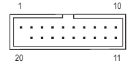
F_U320G (USB Type-C ® Header with USB 3.2 Gen 2x2 Support)
The header conforms to USB 3.2 Gen 2x2 specification and can provide one USB port.

| Pin No. | Definition | Pin No. | Definition |
| 1 | VBUS | 11 | VBUS |
| 2 | TX1+ | 12 | TX2+ |
| 3 | TX1- | 13 | TX2- |
| 4 | GND | 14 | GND |
| 5 | RX1+ | 15 | RX2+ |
| 6 | RX1- | 16 | RX2- |
| 7 | VBUS | 17 | GND |
| 8 | CC1 | 18 | D- |
| 9 | SBU1 | 19 | D+ |
| 10 | SBU2 | 20 | CC2 |
F_U32_1/F_U32_2 (USB 3.2 Gen 1 Headers)
The headers conform to USB 3.2 Gen 1 and USB 2.0 specification and each header can provide two USB ports. For purchasing the optional 3.5" front panel that provides two USB 3.2 Gen 1 ports, please contact the local dealer.
| Pin No. | Definition | Pin No. | Definition |
| 1 | VBUS | 11 | D2+ |
| 2 | SSRX1- | 12 | D2- |
| 3 | SSRX1+ | 13 | GND |
| 4 | GND | 14 | SSTX2+ |
| 5 | SSTX1- | 15 | SSTX2- |
| 6 | SSTX1+ | 16 | GND |
| 7 | GND | 17 | SSRX2+ |
| 8 | D1- | 18 | SSRX2- |
| 9 | D1+ | 19 | VBUS |
| 10 | NC | 20 | No Pin |
F_USBI/F USB2 (USB 2.0/1.1 Headers)
The headers conform to USB 2.0/1.1 specification. Each USB header can provide two USB ports via an optional USB bracket. For purchasing the optional USB bracket, please contact the local dealer.

| Pin No. | Definition |
| 1 | Power (5V) |
| 2 | Power (5V) |
| 3 | USB DX- |
| 4 | USB DY- |
| 5 | USB DX+ |
| 6 | USB DY+ |
| 7 | GND |
| 8 | GND |
| 9 | No Pin |
| 10 | NC |
Prior to installing the USB bracket, be sure to turn off your computer and unplug the power cord from the power outlet to prevent damage to the USB bracket.
SPI_TPM (Trusted Platform Module Header)
You may connect an SPI TPM (Trusted Platform Module) to this header.

| Pin No. | Definition |
| 1 | Data Output |
| 2 | Power (3.3V) |
| 3 | No Pin |
| 4 | NC |
| 5 | Data Input |
| 6 | CLK |
| 7 | Chip Select |
| 8 | GND |
| 9 | IRQ S F_ |
| 10 | NC |
| 11 | NC |
| 12 | RST B S S_F |
THB_U4 (Add-in Card Connector)
This connector is for a GIGABYTE add-in card.
")
NOISE SENSOR (Noise Detection Header)
This header can be used to connect a noise detection cable to detect the noise inside the case.
")
| Pin No. | Definition |
| 1 | Noise Detection |
| 2 | GND |

For more information on the noise detection function, please navigate to the "Unique Features" page of GIGABYTE's website and search for "FAN CONTROL."
Before connecting the cable to the header, make sure to remove the jumper cap; re-place the jumper cap if the header is not in use.
RST (Reset Jumper)
The reset jumper can connect to the reset switch on the chassis front panel. Press the reset switch to restart the computer if the computer freezes and fails to perform a normal restart.
")
| Pin No. | Definition |
| 1 | Reset |
| 2 | GND |

The reset jumper provides you with several functions to use. To remap the button to perform different tasks, please navigate to the "BIOS Setup" page of GIGABYTE's website and search for "RST_SW (MULTIKEY)" for more information.
CLR CMOS (Clear CMOS Jumper)
Use this jumper to clear the BIOS configuration and reset the CMOS values to factory defaults. To clear the CMOS values, use a metal object like a screwdriver to touch the two pins for a few seconds.
")
![warning]()
Always turn off your computer and unplug the power cord from the power outlet before clearing the CMOS values.- After system restart, go to BIOS Setup to load factory defaults (select Load Optimized Defaults) or manually configure the BIOS settings (please navigate to the "BIOS Setup" page of GIGABYTE's website for more information).
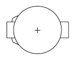
BAT (Battery)
The battery provides power to keep the values (such as BIOS configurations, date, and time information) in the CMOS when the computer is turned off. Replace the battery when the battery voltage drops to a low level, or the CMOS values may not be accurate or may be lost.
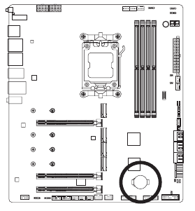
You may clear the CMOS values by removing the battery![]()
- Turn off your computer and unplug the power cord.
- Gently remove the battery from the battery holder and wait for one minute. (Or use a metal object like a screwdriver to touch the positive and negative terminals of the battery holder, making them short for 5 seconds.)
- Replace the battery.
- Plug in the power cord and restart your computer.
![warning]()
Always turn off your computer and unplug the power cord before replacing the battery.- Replace the battery with an equivalent one. Damage to your devices may occur if the battery is replaced with an incorrect model.
- Contact the place of purchase or local dealer if you are not able to replace the battery by yourself or uncertain about the battery model.
- When installing the battery, note the orientation of the positive side (+) and the negative side (-) of the battery (the positive side should face up).
- Used batteries must be handled in accordance with local environmental regulations.
BIOS Setup
BIOS (Basic Input and Output System) records hardware parameters of the system in the CMOS on the motherboard. Its major functions include conducting the Power-On Self-Test (POST) during system startup, saving system parameters and loading operating system, etc. BIOS includes a BIOS Setup program that allows the user to modify basic system configuration settings or to activate certain system features.
When the power is turned off, the battery on the motherboard supplies the necessary power to the CMOS to keep the configuration values in the CMOS.
To access the BIOS Setup program, press the <Delete> key during the POST when the power is turned on.
To upgrade the BIOS, use either the GIGABYTE Q-Flash or Q-Flash Plus utility.
- Q-Flash allows the userto quickly and easily upgrade or back up BIOS without entering the operating system.
- Q-Flash Plus allows you to update the BIOS when your system is off (S5 shutdown state). Save the latest BIOS on a USB thumb drive and plug it into the dedicated port, and then you can now flash the BIOS automatically by simply pressing the Q-Flash Plus button.
For instructions on using the Q-Flash and Q-Flash Plus utilities, please navigate to the "Unique Features" page of GIGABYTE's website and search for "BIOS Update Utilities."
![warning]()
Because BIOS flashing is potentially risky, if you do not encounter problems using the current version of BIOS, it is recommended that you not flash the BIOS. To flash the BIOS, do it with caution. Inadequate BIOS flashing may result in system malfunction.- It is recommended that you not alter the default settings (unless you need to) to prevent system instability or other unexpected results. Inadequately altering the settings may result in system's failure to boot. If this occurs, try to clear the CMOS values and reset the board to default values.
- Refer to the introductions of the battery/clear CMOS jumper in Hardware Installation Chapter or navigate to the "BIOS Setup" page of GIGABYTE's website and search for "Load Optimized Defaults" for how to clear the CMOS values.
![]() Please visit GIGABYTE's website for details on configuring BIOS Setup.
Please visit GIGABYTE's website for details on configuring BIOS Setup.
https://www.gigabyte.com/WebPage/917/amd600-bios.html
Startup Screen:
The following startup Logo screen will appear when the computer boots.

Function Keys
<DEL>: BIOS SETUP\Q-FLASH
Press the <Delete> key to enter BIOS Setup or to access the Q-Flash utility in BIOS Setup.
<F12>: BOOT MENU
Boot Menu allows you to set the first boot device without entering BIOS Setup. In Boot Menu, use the up arrow key <↑> or the down arrow key <↓>to select the first boot device, then press <Enter> to accept. The system will boot from the device immediately.
Note: The setting in Boot Menu is effective for one time only. After system restart, the device boot order will still be based on BIOS Setup settings.
<END>: Q-FLASH
Press the <End> key to access the Q-Flash utility directly without having to enter BIOS Setup first.he Operating System and Drivers
Installing the Operating System and Drivers
Operating System Installation
With the correct BIOS settings, you are ready to install the operating system.
As some operating systems already include RAID driver, you do not need to install separate RAID driver during the Windows installation process. After the operating system is installed, we recommend that you install all required drivers from the GIGABYTE Control Center to ensure system performance and compatibility. If the operating system to be installed requires that you provide additional RAID driver during the OS installation process, please refer to the steps below:
Step 1:
Go to GIGABYTE's website, browse to the motherboard model's web page, download the AMD RAID Preinstall Driver file on the Support\Download\SATA RAID/AHCI page, unzip the file and copy the files to your USB thumb drive.
Step 2:
Boot from the Windows setup disc and perform standard OS installation steps. When the screen requesting you to load the driver appears, select Browse.
Step 3:
Insert the USB thumb drive and then browse to the location of the driver. Select AMD-RAID Bottom Device first and click Next to load the driver. Then select AMD-RAID Controller and click Next to load the driver. Finally, continue the OS installation.

Drivers Installation
After you install the operating system, a dialog box will appear on the bottom-right corner of the desktop asking if you want to download and install the drivers and GIGABYTE applications via GIGABYTE Control Center (GCC). Click Install to proceed with the installation. (In BIOS Setup, make sure Settings\Gigabyte Utilities Downloader Configuration\Gigabyte Utilities Downloader is set to Enabled.)

When the End UserLicenseAgreementdialog box appears, press <Accept> to install GIGABYTE Control Center (GCC). On the GIGABYTE CONTROL CENTER screen, select the drivers and applications you want to install and click Install.


Before the installation, make sure the system is connected to the Internet.
![]() Please visit GIGABYTE's website for more software information.
Please visit GIGABYTE's website for more software information.
https://www.gigabyte.com/WebPage/916/amd600-app.html
![]() Please visit GIGABYTE's website for more troubleshooting information.
Please visit GIGABYTE's website for more troubleshooting information.
https://www.gigabyte.com/WebPage/351/faq.html
Configuring a RAID Set
RAID Levels
| RAID 0 | RAID 1 | RAID 10 | |
| Minimum Number of Hard Drives | ≥2 | 2 | 4 |
| Array Capacity | Number of hard drives * Size of the smallest drive | Size of the smallest drive | Size of the smallest drive * (Number of hard drives/2) |
| Fault Tolerance | No | Yes | Yes |
Before you begin, please prepare the following items:
This motherboard supports RAID 0, RAID 1, and RAID 10. Prepare the correct number of hard drives as indicated in the table above before configuring a RAID array.
- SATA hard drives or SSDs. To ensure optimal performance, it is recommended that you use two hard drives with identical model and capacity.
- Windows setup disc.
- An Internet connected computer.
- A USB thumb drive.
![]() Please visit GIGABYTE's website for details on configuring a RAID array. https://www.gigabyte.com/WebPage/918/amd600-raid.html
Please visit GIGABYTE's website for details on configuring a RAID array. https://www.gigabyte.com/WebPage/918/amd600-raid.html
Debug LED Codes
Regular Boot
| Code | Description |
| 10 | PEI Core is started. |
| 11 | Pre-memory CPU initialization is started. |
| 12~14 | Reserved. |
| 15 | Pre-memory North-Bridge initialization is started. |
| 16~18 | Reserved. |
| 19 | Pre-memory South-Bridge initialization is started. |
| 1A~2A | Reserved. |
| 2B~2F | Memory initialization. |
| 31 | Memory installed. |
| 32~36 | CPU PEI initialization. |
| 37~3A | IOH PEI initialization. |
| 3B~3E | PCH PEI initialization. |
| 3F~4F | Reserved. |
| 60 | DXE Core is started. |
| 61 | NVRAM initialization. |
| 62 | Installation of the PCH runtime services. |
| 63~67 | CPU DXE initialization is started. |
| 68 | PCI host bridge initialization is started. |
| 69 | IOH DXE initialization. |
| 6A | IOH SMM initialization. |
| 6B~6F | Reserved. |
| 70 | PCH DXE initialization. |
| 71 | PCH SMM initialization. |
| 72 | PCH devices initialization. |
| 73~77 | PCH DXE initialization (PCH module specific). |
| 78 | ACPI Core initialization. |
| 79 | CSM initialization is started. |
| 7A~7F | Reserved for AMI use. |
| 80~8F | Reserved for OEM use (OEM DXE initialization codes). |
| 90 | Phase transfer to BDS (Boot Device Selection) from DXE. |
| 91 | Issue event to connect drivers. |
| 92 | PCI Bus initialization is started. |
| 93 | PCI Bus hot plug initialization. |
| 94 | PCI Bus enumeration for detecting how many resources are requested. |
| 95 | Check PCI device requested resources. |
| 96 | Assign PCI device resources. |
| 97 | Console Output devices connect (ex. Monitor is lighted). |
| 98 | Console input devices connect (ex. PS2/USB keyboard/mouse are activated). |
| 99 | Super IO initialization. |
| 9A | USB initialization is started. |
| 9B | Issue reset during USB initialization process. |
| 9C | Detect and install all currently connected USB devices. |
| 9D | Activated all currently connected USB devices. |
| 9E~9F | Reserved. |
| A0 | IDE initialization is started. |
| A1 | Issue reset during IDE initialization process. |
| A2 | Detect and install all currently connected IDE devices. |
| A3 | Activated all currently connected IDE devices. |
| A4 | SCSI initialization is started. |
| A5 | Issue reset during SCSI initialization process. |
| A6 | Detect and install all currently connected SCSI devices. |
| A7 | Activated all currently connected SCSI devices. |
| A8 | Verify password if needed. |
| A9 | BIOS Setup is started. |
| AA | Reserved. |
| AB | Wait user command in BIOS Setup. |
| AC | Reserved. |
| AD | Issue Ready To Boot event for OS Boot. |
| AE | Boot to Legacy OS. |
| AF | Exit Boot Services. |
| B0 | Runtime AP installation begins. |
| B1 | Runtime AP installation ends. |
| B2 | Legacy Option ROM initialization. |
| B3 | System reset if needed. |
| B4 | USB device hot plug-in. |
| B5 | PCI device hot plug. |
| B6 | Clean-up of NVRAM. |
| B7 | Reconfigure NVRAM settings. |
| B8~BF | Reserved. |
| C0~CF | Reserved. |
S3 Resume
| Code | Description |
| E0 | S3 Resume is stared (called from DXE IPL). |
| E1 | Fill boot script data for S3 resume. |
| E2 | Initializes VGA for S3 resume. |
| E3 | OS S3 wake vector call. |
Recovery
| Code | Description |
| F0 | Recovery mode will be triggered due to invalid firmware volume detection. |
| F1 | Recovery mode will be triggered by user decision. |
| F2 | Recovery is started. |
| F3 | Recovery firmware image is found. |
| F4 | Recovery firmware image is loaded. |
| F5~F7 | Reserved for future AMI progress codes. |
Error
| Code | Description |
| 50~55 | Memory initialization error occurs. |
| 56 | Invalid CPU type or speed. |
| 57 | CPU mismatch. |
| 58 | CPU self test failed or possible CPU cache error. |
| 59 | CPU micro-code is not found or micro-code update is failed. |
| 5A | Internal CPU error. |
| 5B | Reset PPI is failed. |
| 5C~5F | Reserved. |
| D0 | CPU initialization error. |
| D1 | IOH initialization error. |
| D2 | PCH initialization error. |
| D3 | Some of the Architectural Protocols are not available. |
| D4 | PCI resource allocation error. Out of Resources. |
| D5 | No Space for Legacy Option ROM initialization. |
| D6 | No Console Output Devices are found. |
| D7 | No Console Input Devices are found. |
| D8 | It is an invalid password. |
| D9~DA | Can't load Boot Option. |
| DB | Flash update is failed. |
| DC | Reset protocol is failed. |
| DE~DF | Reserved. |
| E8 | S3 resume is failed. |
| E9 | S3 Resume PPI is not found. |
| EA | S3 Resume Boot Script is invalid. |
| EB | S3 OS Wake call is failed. |
| EC~EF | Reserved. |
| F8 | Recovery PPI is invalid. |
| <F9> | Recovery capsule is not found. |
| FA | Invalid recovery capsule. |
| FB~FF | Reserved. |

Documents / Resources
References
Remove M.2
GIGABYTE AMD 600 Series BIOS Setup
GIGABYTE Troubleshooting Manual
GIGABYTE AMD 600 Series BIOS Setup
![www.gigabyte.com]() Utility | Service / Support - GIGABYTE Global
Utility | Service / Support - GIGABYTE GlobalGIGABYTE Realtek Audio
M.2 EZ-Latch PLUS
GIGABYTE Motherboards Software Manual
Download manual
Here you can download full pdf version of manual, it may contain additional safety instructions, warranty information, FCC rules, etc.
Advertisement


Need help?
Do you have a question about the X670E AORUS MASTER and is the answer not in the manual?
Questions and answers