Table of Contents
Advertisement
OPERATION & MAINTENANCE
HANDBOOK
Red
Rhino
Crushers (UK) Ltd
Isaac Newton Way
Serial Number
5200110
Grantham
Lincolnshire
Date of manufacture
January 2022
NG31 9RT
United Kingdom
Publication Number
511015
Publication Date
July 2022
Tel: +44 (0) 1476 590 790
E-mail: info@redrhinocrushers.net
Web: www.redrhinocrushers.com
Advertisement
Table of Contents

Related Manuals for Red Rhino 5000 PLUS Series

Summary of Contents for Red Rhino 5000 PLUS Series
- Page 1 OPERATION & MAINTENANCE HANDBOOK Rhino Crushers (UK) Ltd Isaac Newton Way Serial Number 5200110 Grantham Lincolnshire Date of manufacture January 2022 NG31 9RT United Kingdom Publication Number 511015 Publication Date July 2022 Tel: +44 (0) 1476 590 790 E-mail: info@redrhinocrushers.net Web: www.redrhinocrushers.com...
- Page 3 The purpose of this manual is to give a quick reference to the owner and operators of the Red Rhino 5000 Plus. For more Technical, Maintenance and Operational Information please refer to the following: Kubota Engine Operations Manual Red Rhino Technical / Service Department Email: service@redrhinocrushers.net...
-
Page 4: Table Of Contents
Contents Terms & Definitions………………….……………………………………………..…………………………………………………..5 Warranty…………………………………………………………………………………………………..…………………………………6-8 Warranty Registration and Installation Certificate………………………………………………………………….….9-10 EU Declaration of Conformity………………………………………………………………………………………………………..11 Introduction to the Handbook………………………………………………………………………………………….……...12-14 Warning Labels & Symbols…………………………………………………………………………………………………………...15 Stopping the Machine in an Emergency…………………………………………………………………………………….….16 Component Locations………………………………………………………………………………………………………….…….….17 General Safety……………………………………………………………………………………………………………..…………..18-20 Operating Safety…………………………………………………………………………………………………………..……...….21-22 Maintenance Safety……………………………………………………………………………………………..……………………….23 Operation Instructions/ Environment ……………………………………..………………………….…………………..24-25 Crushing ………………….………………………………………………………………………………….……..……………………26/27 Operation Instructions…………………………………………………………………………………………..……………………..28 Pre-Start Safety Checks…………………………………………………………….……………………….…….……………...29/31... -
Page 5: Terms & Definitions
Terms & Definitions For the purposes of this document, the terms and definitions given in ISO 6165 and the following apply. Left-hand side Side which is on the left when an observer is facing in the normal forward direction of travel of the machine. -
Page 6: Warranty
Warranty Terms, Conditions & Procedures- Warranty Terms and Conditions. Your Red Rhino 5000 Plus series Compact Crusher has been designed and manufactured in the UK and meets all current EU legislations on safety, emissions and noise levels. The product is warranted against any defects in material and workmanship for a period of 1 year or 1000 hours usage, from date of installation, whichever occurs first. - Page 7 The warranty liability of Red Rhino Crushers (UK) Ltd is restricted in all cases to the repair or re- placement of the defective part (s), and no liability is accepted for consequential damage or any other expense, loss, or costs (including loss of profit). Red Rhino Crushers (UK) Ltd may actuate the repair or provide compensation in the form of a credit note only, for labour incurred in actuat- ing the repair.
- Page 8 Rhino Crushers (UK) Ltd service record documentation. Service Bulletins Red Rhino Crushers (UK) Ltd may from time to time issue service bulletins to keep you up to date as to any developments or changes that take place on the complete assembly or compo-...
-
Page 9: Warranty Registration And Installation Certificate
It is mandatory that the Warranty Registration and Installation Certificates are completed, signed and returned by the original purchaser to Red Rhino Crushers (UK) Ltd. This is essential for the Red Rhino Warranty Registration & Installation Certificate, and Kubota engine manufacturers Warranty Certificate. - Page 10 DELIVERY DATE: ___________________ I confirm that I have been instructed on the safe use of the Red Rhino Crusher or Screener as detailed above, and that I have retained and read a copy of the operator instruction manual in full and that I un- derstand the terms of the warranty.
-
Page 11: Eu Declaration Of Conformity
Machinery Directive as amended and the National Laws and Regulations adopting this directive. Machine Description: Track mounted compact diesel/hydraulic powered jaw crusher for recycling all types of aggregate based building materials. MAKE: Red Rhino Crusher MODEL: 5000 Plus Series SERIAL NUMBER: ENGINE NUMBER NAME of MANUFACTURER: Red Rhino Crushers (UK) Limited... - Page 12 The technical documentation for the machinery is available from: Red Rhino Crushers (UK) Ltd Isaac Newton Way, Alma Park Industrial Estate, Grantham, Lincs, NG31 9RT Signed for & on behalf of Red Rhino Crushers (UK) Ltd Date of Issue ---------------January 2023----- Andrew Hall...
-
Page 13: Introduction To The Handbook
If the machine is used in any way contrary to its intended use, or if the machine is modified or altered in any way without the prior written consent of Red Rhino Crushers (UK) Ltd, or if the machine is... - Page 14 It must not be removed from the machine and should be kept clean and in good condition always. Additional copies of the handbook can be obtained from Red Rhino Crushers (UK) Ltd. Only trained operators should use this machine. Red Rhino Crushers (UK) Ltd strongly rec- ommends that anyone who is responsible for the operation and servicing of this machine be a fully trained &...
- Page 15 Caution Denotes a reminder of safety practices could result in injury to the operator (or others) and possible damage to the machine. In general, these notes are used to indicate that the procedures being described in the hand- book must be followed to avoid serious injury or death, to yourself or others. The notes are also used to protect the machine from unsafe servicing practices.
-
Page 16: Warning Labels & Symbols
Warning Labels & Symbols Danger of Trapping Emergency Stop Wear P.P.E. Tie Down Points... -
Page 17: Stopping The Machine In An Emergency
Stopping the Machine in an Emergency Warning The machine can be stopped in an emergency by pressing the • emergency stop buttons located along each side of the machine or by turning the ignition key directly to the “off” position. Make sure that all persons in the area of the machine are fully •... -
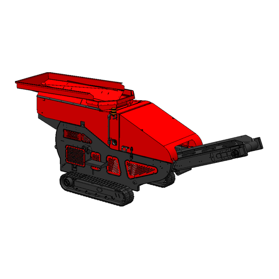
Page 18: Component Locations
Component Locations... -
Page 19: General Safety
You and others could be killed or seriously injured if you operate or maintain the ma- chine without first studying the operator manual. You must understand and follow the instructions in the operator manual. If you do not understand anything, ask your employer or Red Rhino dealer to explain it. Warning Care and alertness: All the time you •... - Page 20 Warning Feeling unwell: • Do not attempt to operate the machine if you are feeling unwell. By doing so you could be a danger to yourself and those you work with. Warning Mobile Phones: • Switch off your mobile phone before entering an area with a potentially ex- plosive atmosphere;...
- Page 21 Warning Lifting: • This machine is NOT permitted to be lifted for transport or any other rea- son. Warning Power Source: • Before any maintenance, service or adjustments are carried out on the ma- chine the “POWER SOURCE” must be isolated. Any persons carrying out repairs or maintenance must isolate the machine and remove the ignition control key.
-
Page 22: Operating Safety
Operating Safety Warning Machine Condition: • A defective machine can injure you or others. Do not operate a machine which is defective or has missing parts. Make sure the maintenance proce- dures in this manual are completed before using the machine. Warning Airborne Debris: •... - Page 23 Warning Transportation: • Make sure that any trailer or vehicle is suitable to transport the machine and meets all road traffic regulations. • Before moving the machine onto a trailer or vehicle, make sure that load bed and ramps are free from oil, grease, ice and mud. •...
-
Page 24: Maintenance Safety
Maintenance Safety Warning Repairs: • If your machine does not function correctly in any way, get it repaired straight away. Neglect of necessary repairs could result in an accident or affect your health. • Do not try to do repairs or any other type of maintenance work you do not understand. - Page 25 Ensure this section is read fully before using the machine. If any part is un- clear please consult your employer or Red Rhino Dealer. Once read and understood, practice with the machine in an open space, clear of any hazards or peo- ple to ensure you are comfortable with the machine and understand all the controls before use in a work environment.
- Page 26 Operating Environment Introduction - This machine is designed to operate in temperatures between -15°C and 40°C. Operating in a Cold Climate (Below 0°C) To account for extremely low temperatures ensure extra time is provided for the warm up of the crusher. Following the warm up time ensure that the crusher and conveyor are functioning correctly before use.
- Page 27 Crushing All crushing should be done on a level surface- Safety Warnings • Crushing machine uses powerful moving jaws so under no circumstances should the machine run without all covers attached or when moving parts are exposed. Safety Warnings • Under no circumstances should you attempt to remove blockages by hand.
- Page 28 It may be possible to also crush steel reinforced concrete though you should first consult your Red Rhino dealer in order to determine if your machine is capable. • If unsure of a material for crushing consult your Red Rhino dealer for information. Unsuitable Materials for Crushing •...
-
Page 29: Operation Instructions/ Environment
Operation Instructions Gradient Transportation: When loading the Machine for transport, the ramp must not exceed 25°. It should also be noted that ground conditions should be taken into consideration as to whether the conditions are wet or slippery because this will greatly reduce this value. Travelling: When moving the machine slope of the ground should not exceed 15°... -
Page 30: Pre-Start Safety Checks
Pre-Start Safety Checks The following checks must be carried out prior to commencing work. Particular attention must be given if the machine has been left idle for any period of time. All of these checks concern the continued operation of the machine and some concern your safety. Any defects should be inspected and corrected by your distributor or service engineer. - Page 31 Guidance to Machine Pre-Start Checks Engine Oil Dipstick Hydraulic Oil Level Gauge Fuel Level Gauge...
- Page 32 Air Cleaner Element Filter Ele- ment Coolant Level Indicator Remote Handset Charge Adaptor 240 V Charger...
-
Page 33: Engine Controls
Engine Controls Control Panel- The control panel box (shown above) is located on the nearside rear enclosure of the ma- chine. Please refer to the following pages for an in depth breakdown of the control panel. Throttle Control - The throttle lever, which controls the Engine Speed (shown above) can be found on the rear nearside enclosure of the machine. - Page 34 Control Panel Indication Lights- Engine Temperature Indicator Engine Running Illuminates to show When illuminated & the the engine tempera- key is in the ON position ture is too high, cool- or the engine is running. ing fan belt is slipping, broken or the cooler/ matrix is blocked.
-
Page 35: Remote Handset
Remote Handset The Remote Handset operates the machine via the radio receiver. This handset has a charging adaptor for mains current charging. For radio operation the handset must be kept charged. If the handset battery becomes flat the umbilical cord connection can be used. Please refer to the umbilical cord connection picture below. - Page 36 Remote Handset Crusher Charging Jaws On / Off Connection Reverse Jaws Out Magnet Vibratory Conveyor Feeder Slow Jaws In Main Conveyor Horn Vibratory Feeder on/off Vibratory Feeder Speed Left Track Increase Mode Forward / Light Reverse Right Track On / Off Forward / Reverse...
-
Page 37: Radio Receiver
Radio Receiver Pairing Handset 1. Turn ignition ON (Do not start) Turn handset ON. 2. Locate receiver on the side of the machine just above control panel. 3. Press blue button on receiver and light will go to orange. 4. Press and hold down the horn, jaw in and jaw out, all at the same time. If correctly paired the handset light will turn green. -
Page 38: Discharge Conveyor
Discharge Conveyor Starting the Conveyor system - Before attempting to crush any material, you should first ensure that the conveyor is running so there will not be a build-up on material in the crusher. The conveyor is started by using the touch pad on the remote control, when using the radio remote con- trol the conveyor will stop after 30 seconds if the remote signal is lost. - Page 39 Conveyor Side Wear The Conveyor is fitted with side Rubber wear rubber skirting to prevent Skirting any spillages. Conveyor Grease Point The Head-drum Bearings are fit- Grease Point ted with grease points left hand side and right hand side. Conveyor Motor Drive Assembly Coupling The Conveyor drive coupling is a direct drive assembly and requires...
-
Page 40: Dust Suppression
Dust Suppression Dust Suppression Spray Bar A dust suppression water spray & Nozzles bar is mounted above the con- veyor discharge belt. This cross belt assembly is fitted with three water nozzle jet valves. Connection Point A mains water supply is required to connect to the spray bar. -
Page 41: Vibrating Feeder
Vibrating Feeder The Vibrating Feeder is capable of handling a wide range of products, such as minerals, aggregates, re- cyclables and limestone. The feeder is Hydraulically driven and vibration is controlled by the feeder pan being mounted on 4 x Vi- brating Rosta Mounts. -
Page 42: Feeder Lubrication Detail
Feeder Lubrication Detail Oil Filler / Breather Plug Oil Level Oil Drain Plug Plug The feeder only requires the oil level to be maintained and the bearings to be greased on occasion. Oil Level - The Oil Level plug should be checked every 250 hours and the correct level must be maintained. - Page 43 Running Gear (Rubber Tracks) Checking tracks for cuts and abrasions: Whilst visually inspecting the tracks, attention should also be taken for any signs of wear on the tracks such as damage that may indicate the tracks need to be replaced. Warning •...
-
Page 44: Running Gears (Tracks)
Running Gears (Tracks) Track Adjustment After maintenance or over time the Track will become slack and will have to be adjusted. The adjustment of the tracks operates through a Tensioning Cylinder (C). When the Cylinder is filled with grease it extends and pushes the Spring Tension unit (B), and the Idler (A), forward. - Page 45 Gear Box Oil Level Important: Cleanliness is essential when checking, filling or replacing oil in the gearbox. Gearbox operating life will be dramatically shortened if the oil becomes contaminated. Only use new clean oil in clean containers and fillers. A. Check and Filling Gearbox Oil Move the Host Machine to a level surface and bring the oil fill and oil drain holes to the posi- Left Hand...
-
Page 46: Jaw Crusher Unit
Jaw Crusher Unit CRUSHER FLYWHEEL Jaws Unit The Jaw Crusher Unit is an integral part of the crusher and is situated CRUSHER centrally within the chassis. DRIVE BELTS Power BELT The crusher is hydraulically driven TENSIONERS via flywheels, belt and tensioner to give the crusher reciprocating mo- tion. - Page 47 Motion & Sizing HYDRAULIC Hydraulic rams are operated from the remote control. This operates a wedge system to narrow or widen the bottom opening of the jaw. This adjustment al- lows the sizing of the discharge crushed material. Greasing Bearings GREASING The crusher box has a central greasing point for the inner and outer bearings, situ-...
-
Page 48: Guide To Servicing Your Machine
Guide to Servicing Your Machine For full engine service details, please refer to the Kubota Engine Manual For service and technical assistance please contact RRC; Email: service@redhinocrushers.net Telephone: +44 (0) 1476 590790 Engine The engine oil dipstick and oil drain plug are accessible through the rear engine access door at the front of the engine. - Page 49 Air Filtration The Air Filter Element is accessible through the rear right hand side access guard. Remove the element end cap and pull out the primary and secondary filters. Daily- inspections cleaning out dust, for changes refer to the Kubota Engine Manual. Air Filter Element Air Filters Fuel System...
- Page 50 Cooling System The radiator cooling system is filled through the filler cap on top of the header tank. The coolant level gauge is on the front face of the tank. Daily—check the fan belt adjustment and the condition, referring to the Kubota Engine Manual. Belt Header Tank Engine...
- Page 51 FILTER LEVEL GUAGE Hydraulic Filter CRUSHER Check the jaw plates for wear, if evident reverse or replace plates. Check the drive belt for alignment damage and tensioning. Contact Red Rhino service for their jaw maintenance procedures. TENSIONING ROSTA Jaw Box...
- Page 52 Emergency Stop Buttons Check all the emergency stops are working daily to ensure maximum safety. These can be located on either side of the machine. Tracks Check track gearbox oil levels every 500 running hours. Check track tension daily and apply EP2 grease to tension when required.
-
Page 53: Hydraulic Manual Controls
Note: This system is for recovery or maintenance in the case of electronic failure only. Left Hand Right Hand Spool Feeder/ Conveyor Spool Crusher/ Tracks/ Jaw Service Data Gauges The spools also have pressure gauges to obtain system pressure information. These are a useful aid to diagnose the hydraulic issues for Red Rhino Service. -
Page 54: Hydraulic Circuit
Hydraulic Circuit... - Page 55 Engine Start Panel...
- Page 56 Engine Harness...
- Page 57 IO Power/CAN Harness...
- Page 58 Valve Harness...
- Page 59 E Stop Harness...
- Page 60 Optional Extra — Over Band Magnet Benefits The addition of magnet arms will remove any magnetic objects that may have passed through the crusher, preventing them from ending up in the final stock pile. These materials can damage the conveyor belt and effect the purity of the end product. Over Band Connection MAGNET The over band magnet is suspended...
- Page 61 Optional Extra - Feeder Sensor Sonar...
- Page 62 Optional Extra — Screening Attachment Benefits The addition of the RRC 5000 screener is one of the most effective ways of sorting the pro- cessed material, otherwise impossible by hand. The screener attachment will sort the previ- ously crushed material through a screener via the momentum of the machine, into useful stock size piles, dependant on mesh.
-
Page 63: Replacement Parts
Replacement Parts For replacement parts and / or spares you will need to quote the Red Rhino model and engine serial number. Red Rhino will provide an additional recommended Spares List for your machine. These are available from the Red Rhino Parts and Service Department. -
Page 64: Model Specifications
Model Specifications Model 5000 Plus Prime Mover Type Internal Combustion Engine Power Installed 18.5kW (24.8hp) Length 5600mm Vibrating Feeder Length - less conveyor 4100mm Overall dimensions in General Data operating mode Width 1665mm Height 2080mm Mass in operating mode 3170kg Mass in transporting mode 3170kg Ground Clearance... -
Page 65: General Arrangement Dimension
General Arrangement Dimension Rear View Side View... - Page 66 RED RHINO MINI CRUSHERS (UK) LTD. NOISE EMISSION DATA IN ACCORDANCE WITH – MACHINERY DIRECTIVE 2006/42/EC OUTDOOR NOISE DIRECTIVE 2000/14/EC NOMAD (9) 2016 NOISE MACHINERY PROJECT. RED RHINO MODEL 5000Plus Equipment Type THIS EQUIPMENT HAS THE FOLLOWING NOISE EMISSION DATA COMPILED – NOVEMBER 2022. UNDER NON- CRUSHING CONDITIONS.
- Page 67 An example is shown below. HEARING PROTECTION MUST BE WORN! Owners of a Red Rhino machine should carry out further noise testing and risk assessments to reflect the relevant site conditions where the machine is in operation...
Need help?
Do you have a question about the 5000 PLUS Series and is the answer not in the manual?
Questions and answers