
Related Manuals for Automationdirect.com prosense PPC5 Series


Summary of Contents for Automationdirect.com prosense PPC5 Series
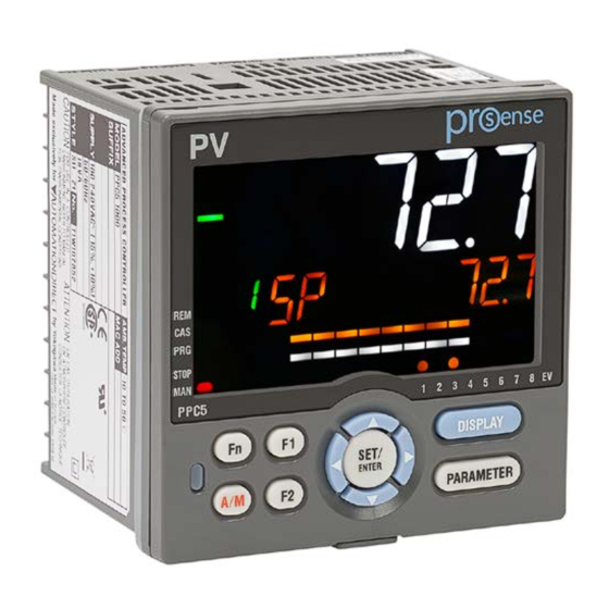
- Page 1 User Manual ProSense Advanced Process Controllers PPC5 Series Models: PPC5-1000 PPC5-1001 PPC5-1002 PPC5-1100 PPC5-1101 PPC5-1102...
- Page 2 ProSense Advanced Process Controllers Please include the Manual Number and the Manual Issue, both shown below, when communicating with Technical Support regarding this publication. Manual Number: PPC5-USER-M Issue: 1st Edition Issue Date: 04/20 Publication History Issue Date Description of Changes 1st Edition 04/20 Original Issue...
-
Page 3: Table Of Contents
Preface Preface Contents Overview of this Publication ..........................a Who Should Read This Manual ......................... a Safety Precautions ............................a Handling Precautions for the Controller ......................c Checking the Contents of the Package ......................c PPC5 Models and Description ........................... d Symbols Used in This Manual .......................... - Page 4 Preface Communication Functions ......................... 2-6 Names and Functions of Display Parts ..................... 2-8 Names and Functions of Keys ......................2-10 List of Display Symbols ........................2-11 Overview of Display Switch and Operation Keys ................2-13 How to Set Parameters ........................2-16 Chapter 3 - Quick Setting Function .................3-1 Setting Using Quick Setting Function ....................
- Page 5 Preface 6.1.4 Cascade Control ..........................6-8 6.1.5 Loop Control for Backup ........................6-10 6.1.6 Loop Control with PV Switching ......................6-12 6.1.7 Loop Control with PV Auto-selector ....................6-14 6.1.8 Loop Control with PV-hold Function ....................6-16 Setting Control Type (CNT) ......................6-18 6.2.1 PID Control ............................6-19 6.2.2 ON/OFF Control (1 point of hysteresis / 2 points of hysteresis) ............6-20 6.2.3...
- Page 6 Preface Chapter 9 - Alarm Functions ..................9-1 Setting Alarm Type ..........................9-2 Setting Number of Alarm Groups to Use ..................9-14 Setting Hysteresis to Alarm Operation .................... 9-15 Delaying Alarm Output (Alarm Delay Timer) ................... 9-16 Setting Alarm Output to Control Relay Terminal ................9-17 Setting Alarm Action According to Operation Mode .................
- Page 7 Preface Chapter 14 - Troubleshooting ................14-1 14.1 Troubleshooting ..........................14-2 14.1.1 Troubleshooting Flowchart ........................14-2 14.1.2 Errors at Power On ...........................14-3 14.1.3 Errors during Operation ........................14-5 14.2 Maintenance ..........................14-15 14.2.1 Cleaning ............................14-15 14.2.2 Disposal ............................14-15 Chapter 15 - Parameter Settings ................15-1 15.1 Parameter Map ..........................
- Page 8 Preface 18.3 Ethernet Communication (PPC5-1x02 Models) ................18-4 18.3.1 Communication Specifications ......................18-4 18.4 Coordinated Communication (PPC5-1x01 Models) ................ 18-6 18.4.1 Communication Specifications ......................18-6 Chapter 19 - Communication Settings ..............19-1 19.1 Setting Parameters .......................... 19-2 19.1.1 Setting RS-485 Communication (PPC5-1x01 Models) ..................19-2 19.1.2 Setting Ethernet Communication (PPC5-1x02 Models) ..............19-4 19.1.3...
- Page 9 Preface 22.1 Overview ............................22-2 22.2 Coordinated Items ........................... 22-3 22.3 Starting Coordinated Operation ....................... 22-4 Chapter 23 - D Registers (Holding Registers) ............23-1 23.1 Overview ............................23-2 23.2 Conventions Used in D Register Tables ..................23-3 23.3 Classification of D Registers ......................23-4 23.4 D Registers ............................
- Page 10 Preface Input (Status) Relay and Output (Status) Relay (5025 to 5280) ................24-12 Control (Status) Relay (5281 to 5408) ........................24-12 Internal Relay (5537 to 5792) ...........................24-12 DI Terminals and DO Terminals (6305 to 6560) ......................24-12 viii PPC Manual Revision 1...
-
Page 11: Overview Of This Publication
This category applies to electric equipment that measures a circuit connected to a low-voltage facility and receives power from stationary equipment such as electric switchboards. 1st Edition : April 2020 All Rights Reserved, Copyright © 2020 AutomationDirect.com PPC Manual Revision 1... - Page 12 To use the instrument properly and safely, observe the safety precautions described in this user’ s manual when operating it. Use of the instrument in a manner not prescribed herein may compromise protection features inherent in the device. We assume no liability for or warranty on a fault caused by users’ failure to observe these instructions.
-
Page 13: Handling Precautions For The Controller
WARNING ● Power Supply Ensure that the instrument’ s supply voltage matches the voltage of the power supply before turning ON the power. ● Do Not Use in an Explosive Atmosphere Do not operate the instrument in locations with combustible or explosive gases or steam. -
Page 14: Ppc5 Models And Description
PPC5 Models and Description Model Description ProSense advanced process controller, 1/4 DIN, 2-line alpha-numeric LCD, bar PPC5-1000 graph LCD, current, voltage, RTD, thermocouple, discrete input, current, voltage pulse, relay, retransmission output, 100-240 VAC operating voltage. ProSense advanced process controller, 1/4 DIN, 2-line alpha-numeric LCD, bar PPC5-1001 graph LCD, current, voltage, RTD, thermocouple, discrete input, current, voltage pulse, relay, retransmission output, 100-240 VAC operating voltage, RS-485. - Page 15 Product Name Quantity Brackets Terminal cover Unit label Installation Instructions and User’ s Guide How to use the unit label • Affix the unit label to the front panel. If necessary, combine with unit prefixes. Affix it so that the LCD area is not blocked. •...
-
Page 16: Symbols Used In This Manual
Symbols Used in This Manual This symbol is used on the instrument. It indicates the possibility of injury to the user or damage to the instrument, and signifies that the user must refer to the user’ s manual for special instructions. The same symbol is used in the user’ s manual on pages that the user needs to refer to, together with the term “WARNING”... -
Page 17: Setup Procedure
Setup Procedure The following flowchart shows the setup procedure for the PPC5 controller. Installation Install and wire a controller. and Wiring Power ON Control mode setup Control type setup Control mode: Single-loop control only Control type setup Input/output setup Input setup Output setup Set the other parameters as necessary. -
Page 18: Chapter 1 - Installation And Wiring
Chapter 1 - Installation and Wiring Chapter 1: Installation and Wiring Chapter Installation and Wiring Contents Installation Location ........................... 1-2 Mounting Method ..........................1-4 External Dimensions and Panel Cutout Dimensions ..................1-5 Wiring ..............................1-6 1.4.1 Important Information on Wiring ......................1-6 1.4.2 PV Input Wiring ...........................1-8 1.4.3... -
Page 19: Installation Location
Chapter 1: Installation and Wiring Installation Location The instrument should be installed in indoor locations meeting the following conditions: • This instrument is designed to be mounted in an instrumented panel. Mount the instrument in a location where its terminals will not inadvertently be touched. •... - Page 20 Chapter 1: Installation and Wiring Do not mount the instrument in the following locations: • Outdoors • Locations subject to direct sunlight, infrared rays, ultraviolet rays, or close to a heater Install the instrument in a location with stable temperatures that remain close to an average temperature of 23°C.
-
Page 21: Mounting Method
Chapter 1: Installation and Wiring Mounting Method WARNING Be sure to turn OFF the power supply to the controller before installing it on the panel to avoid an electric shock. Mounting the Controller Provide an instrumented panel steel sheet of 1 to 10 mm thickness. After cutting the mounting hole on the panel, follow the procedures below to install the controller: Insert the controller into the opening from the front of the panel so that the terminal... -
Page 22: External Dimensions And Panel Cutout Dimensions
Chapter 1: Installation and Wiring External Dimensions and Panel Cutout Dimensions Mounting the Controller Unit: mm (approx. inch) (0.43) 65 (2.56) 96 (3.78) Bracket Terminal cover 20 (0.79) Bracket 1 to 10 mm (0.04 to 0.39 inch) (panel thickness) General mounting Side-by-side close mounting +0.8 –... -
Page 23: Wiring
Chapter 1: Installation and Wiring Wiring 1.4.1 Important Information on Wiring WARNING 1) Be sure to turn OFF the power supply to the controller before wiring to avoid an electric shock. Use a tester or similar device to ensure that no power is being supplied to a cable to be connected. - Page 24 Chapter 1: Installation and Wiring Recommended Crimp-on Terminal Lugs (ød ) Recommended tightening torque: 0.6 N·m Applicable wire size: Power supply wiring 1.25 mm or more Applicable terminal lug Applicable wire size mm (AWG#) (ød) 0.25 to 1.65 (22 to 16) 5.5 3.3 Cable Specifications Purpose...
-
Page 25: Pv Input Wiring
Chapter 1: Installation and Wiring 1.4.2 PV Input Wiring CAUTION 1) Be careful of polarity, for voltage and milliamp input, when wiring inputs. Reversed polarity can damage the controller. 2) Keep the PV input signal line as far away as possible from the power supply circuit and ground circuit. -
Page 26: Remote Auxiliary Analog Input Wiring (Ppc5-110X Models)
Chapter 1: Installation and Wiring 1.4.3 Remote Auxiliary Analog Input Wiring (PPC5-110x models) CAUTION 1) Be careful of polarity when wiring inputs. Reversed polarity can damage the controller. 2) Keep the remote auxiliary analog input signal line as far away as possible from the power supply circuit and ground circuit. -
Page 27: Control Output (Relay, Current And Voltage Pulse) Wiring
Chapter 1: Installation and Wiring 1.4.4 Control Output (Relay, Current and Voltage Pulse) Wiring CAUTION 1) The use of inductive (L) loads such as auxiliary relays, motors and solenoid valves may cause malfunction or relay failure; it is recommended to insert a CR filter for use with alternating current or a diode for use with direct current, as a spark-removal surge suppression circuit, into the line in parallel with the load. - Page 28 Chapter 1: Installation and Wiring Relay Output Contact rating: 250 V AC, 3 A 30 V DC, 3 A (resistance load) Note: The control output should always be used with a load of 10 mA or more. Current and Voltage Pulse Output Shield –...
-
Page 29: Contact Input Wiring
Chapter 1: Installation and Wiring 1.4.5 Contact Input Wiring CAUTION 1) Use a dry contact (relay contact etc.) for external contacts. 2) Use a dry contact which has ample switching capacity for the terminal's OFF voltage (approx. 5V) and ON current (approx 1mA). 3) When using a transistor contact, the voltage at both terminals must be 2 V or less when the contact is ON and the leakage current must be 100 µA or less when it is OFF. - Page 30 Chapter 1: Installation and Wiring The following table shows the initial setting for each control mode. No function is assigned to contact inputs other than those listed below. DI16 Control mode (PPC5-110x models) AUTO (ON)/ STOP (ON)/ Remote (ON)/ Single-loop Control MAN (OFF) RUN (OFF) None...
-
Page 31: Alarm Contact Output Wiring
Chapter 1: Installation and Wiring 1.4.6 Alarm Contact Output Wiring CAUTION 1) Use an auxiliary relay for load-switching if the contact rating is exceeded. 2) Connect a bleeder resistor when a small current is used, so that a current exceeding 1 mA can be supplied. 3) The output relay has a limited service life. -
Page 32: Retransmission Output Wiring
Chapter 1: Installation and Wiring 1.4.7 Retransmission Output Wiring Shield terminals terminals – Receiver (Recorder etc.) Receiving resistor: Grounding Ω or less The current output range can be changed. When retransmission output is not used for retransmission output, it can be used for 15 V DC loop power supply. -
Page 33: Communication Interface Wiring (Ppc5-1X01 Models)
Chapter 1: Installation and Wiring 1.4.9 RS-485 Communication Interface Wiring (PPC5-1x01 Models) Connection to a PC Parameter Setting Software USB-485M (sold separately) PPC5 Black 2-Wire Cable (supplied with USB-485M, not sold separately). PPC5 USB-485M USB-485M Adapter Process Controller black 2-wire cable [407] SDB (+) [408] SDA (-) 4 (SG+) -
Page 34: Coordinated Operation Wiring (Ppc5-1X01 Models)
Chapter 1: Installation and Wiring 1.4.10 Coordinated Operation Wiring (PPC5-1x01 Models) 4-wire Wiring PPC5 (Master) PPC5 (Slave) PPC5 (Slave) SDB (+) RDB (+) RDB (+) (External) (External) Terminating resistor Terminating resistor SDA (–) RDA (–) RDA (–) 220 Ω 1/4 W 220 Ω... -
Page 35: Ethernet Communication Interface Wiring (Ppc5-1X02 Models)
Chapter 1: Installation and Wiring 1.4.11 Ethernet Communication Interface Wiring (PPC5-1x02 Models) *Devices that can be *Devices that can be connected via Ethernet connected via Ethernet Ethernet Straight cable Crossover cable PPC5 PPC5 PPC5 Upper side LED RJ45 connector on back of PPC5-1x02 Lower side LED Upper side LED (baud rate) - Page 36 Chapter 1: Installation and Wiring RS-485 communication wiring for the serial gateway function is as follows. 2-wire Wiring of 4-wire Terminal Serial gateway PPC5 PPC5 RDB (+) RDB (+) RSB (+) (External) (External) Terminating resistor Terminating resistor RDA (–) RDA (–) RSA (–) 220 Ω...
-
Page 37: Power Supply Wiring
Chapter 1: Installation and Wiring 1.4.12 Power Supply Wiring WARNING 1) Wiring work must be carried out by a person with basic electrical knowledge and practical experience. 2) Be sure to turn OFF the power supply to the controller before wiring to avoid an electric shock. -
Page 38: Attaching And Detaching Terminal Cover
Chapter 1: Installation and Wiring Attaching and Detaching Terminal Cover After completing the wiring, the terminal cover is recommended to use for the instrument. Attaching Method (1) Attach the terminal cover to the rear panel (2) The following figure is a mounting image. of the controller unit horizontally. -
Page 39: Chapter 2 - Introduction To Unit, Key, And Display Functions
Chapter 2 - Introduction to Unit, Key, and Display Functions Chapter 2 Introduction to Unit, Key, and Display Functions Chapter Introduction to Unit, Key, and Display Functions Contents Definition of Main Symbols and Terms ....................2-2 Input/Output Function ........................2-3 Display and Key Functions ........................ -
Page 40: Definition Of Main Symbols And Terms
Chapter 2 Introduction to Unit, Key, and Display Functions Definition of Main Symbols and Terms Main Symbol PV: Measured input value SP: Target setpoint OUT: Control output value RSP: Remote setpoint A/M: AUTO/MAN C/A/M: CAS/AUTO/MAN AUTO: Automatic MAN: Manual CASCADE, CAS: Cascade REMOTE, REM: Remote LOCAL, LCL: Local E1, E2, E3, and E4: Terminal areas... -
Page 41: Input/Output Function
Chapter 2 Introduction to Unit, Key, and Display Functions Input/Output Function PV Input PV input is a universal input to arbitrarily set the type and range for the thermocouple (TC), resistance-temperature detector (RTD), and DC voltage/current. Current Voltage pulse PPC5 Relay contact 2-wire trans-... - Page 42 Chapter 2 Introduction to Unit, Key, and Display Functions Retransmission Output Retransmission output outputs a PV input value (PV), target setpoint (SP), control output value (OUT) and the like as an analog signal to, for example, a recorder. External device such as recorder etc. Current PPC5 Contact Input...
-
Page 43: Display And Key Functions
Chapter 2 Introduction to Unit, Key, and Display Functions Display and Key Functions Employing a 14-segment, active color LCD greatly increases the monitoring and operating capabilities. Active Color PV Display (display color change) The active color PV display function changes the PV display color (red or white) when abnormality occurs in PV etc. -
Page 44: Communication Functions
Chapter 2 Introduction to Unit, Key, and Display Functions Communication Functions The PPC5 series is available without communication or with RS-485 communication or Ethernet communication depending on the model. RS-485 Communication Modbus (PPC5-1x01 models) The PPC5 can communicate with PCs, PLCs, touch panels, and other devices. Reference Section 1.4.9 RS-485 Communication Interface Wiring (PPC5-1x01 Models) USB-485M (sold separately) - Page 45 Chapter 2 Introduction to Unit, Key, and Display Functions Coordinated Operation A system of coordinated operation is configured with a master controller and a number of slave controllers. The slave controllers are set to operate in the same way as the master controller.
-
Page 46: Names And Functions Of Display Parts
Chapter 2 Introduction to Unit, Key, and Display Functions Names and Functions of Display Parts (9) Deviation indicator (1) PV display (2) Group display (4) Data display (3) Symbol display (10) Status indicator (5) Bar-graph display (11) Security indicator PPC5 (6) Event indicator (12) Ladder - Not used in PPC5 (7) Key navigation indicator... - Page 47 Chapter 2 Introduction to Unit, Key, and Display Functions No. in figure Name Description Displays PV. Displays an error code if an error occurs. PV display Displays the scrolling guide in the Menu Display and (white or red) Parameter Setting Display when the guide display ON/ OFF is set to ON.
-
Page 48: Names And Functions Of Keys
Chapter 2 Introduction to Unit, Key, and Display Functions Names and Functions of Keys PPC5 (1) DISPLAY key (4) Light-loader interface (2) PARAMETER key (5) A/M key (3) SET/ENTER key (6) User function keys Up/Down/Left/Right arrow keys No. in figure Name Description Used to switch the Operation Displays. -
Page 49: List Of Display Symbols
Chapter 2 Introduction to Unit, Key, and Display Functions List of Display Symbols The following shows the parameter symbols, menu symbols, alphanumeric of guide, and symbols which are displayed on the PPC5 controller. Figure (common to all display area) PV display (14 segments): Alphabet Symbol display and Data display (11 segments): Alphabet (lower-case) 2-11... - Page 50 Chapter 2 Introduction to Unit, Key, and Display Functions Group display (7 segments): Alphabet None PV display (14 segments): Symbol Space ‘ 2-12 PPC Manual Revision 1...
-
Page 51: Overview Of Display Switch And Operation Keys
Chapter 2 Introduction to Unit, Key, and Display Functions Overview of Display Switch and Operation Keys The following shows the transition of Operation Display, Operation Parameter Setting Display, and Setup Parameter Setting Display. The “Operation Parameter Setting Display” has the parameters for setting the functions necessary for the operation. - Page 52 Chapter 2 Introduction to Unit, Key, and Display Functions The display pattern of the PPC5 series is as follows; the Menu Display and Parameter Setting Display. Display Description The Menu Display is segmented by the function and optional terminal position. The scrolling guide for the menu is displayed on PV display.
- Page 53 Chapter 2 Introduction to Unit, Key, and Display Functions Display Shown at the End (the Lowest Level) of the Parameter Setting Display As shown in the figure below, the END Display is shown to indicate the end of the Menu Display and Parameter Setting Display.
-
Page 54: How To Set Parameters
Chapter 2 Introduction to Unit, Key, and Display Functions How to Set Parameters The following operating procedure describes an example of setting alarm setpoint (A1). Operation Hold down the PARAMETER key for 3 seconds in the Operation Display to call up the [MODE] Menu Display. - Page 55 Chapter 2 Introduction to Unit, Key, and Display Functions Press the SET/ENTER key to blink the setpoint. Press the Up or Down arrow key to change the setpoint. (Change the setpoint using the Up/Down arrow keys to increase and decrease the value and the Left/Right arrow keys to move between digits.) Press the SET/ENTER key to register the setpoint (the setpoint stops blinking).
- Page 56 Chapter 2 Introduction to Unit, Key, and Display Functions How to Set Parameter Setpoint Numeric Value Setting Display the Parameter Setting Display. Press the SET/ENTER key to move to the setting mode (the setpoint blinks). Press the Left arrow key to move one digit to the left. (Press the Right arrow key to move one digit to the right.) Press the Up or Down arrow key to change the setpoint.
- Page 57 Chapter 2 Introduction to Unit, Key, and Display Functions Time (minute.second) Setting Example of 17 minutes 59 seconds Display the Parameter Setting Display. Press the SET/ENTER key to move to the setting mode (the setpoint blinks). Press the Left arrow key to move one digit to the left. (press the Right arrow key to move one digit to the right.) Press the Up or Down arrow key to change the setpoint.
-
Page 58: Chapter 3 - Quick Setting Function
Chapter 3 - Quick Setting Function Chapter 3: Quick Setting Function Chapter Quick Setting Function Contents Setting Using Quick Setting Function ....................3-2 Restarting Quick Setting Function ..................... 3-7 PPC Manual Revision 1... -
Page 59: Setting Using Quick Setting Function
Chapter 3: Quick Setting Function Setting Using Quick Setting Function Description The Quick setting function is a function to easily set the basic function of the controller. The Quick setting function starts when the power is turned on after wiring. The Quick setting function can be used only when the control mode is Single-loop control. - Page 60 Chapter 3: Quick Setting Function Flowchart of Quick Setting Function Power ON Decide whether or not to use the Quick setting function. Press the UP arrow key to select YES. Press the SET/ENTER key to start the Quick setting function. Press the Down arrow key to select NO.
- Page 61 Chapter 3: Quick Setting Function Setting Example Set the following parameters to set to PID control, thermocouple Type K (range: 0.0 to 500.0ºC), and current control output. No need to change the parameters other than the following parameters. Set QSM = YES to enter the quick setting mode. (1) Set CNT = PID.
- Page 62 Chapter 3: Quick Setting Function Input Function Parameter Display Name Setting range Menu symbol symbol level OFF: Disable K1: -270.0 to 1370.0 ºC / -450.0 to 2500.0 ºF K2: -270.0 to 1000.0 ºC / -450.0 to 2300.0 ºF K3: -200.0 to 500.0 ºC / -200.0 to 1000.0 ºF J: -200.0 to 1200.0 ºC / -300.0 to 2300.0 ºF T1: -270.0 to 400.0 ºC / -450.0 to 750.0 ºF T2: 0.0 to 400.0 ºC / -200.0 to 750.0 ºF...
- Page 63 Chapter 3: Quick Setting Function Input Function (Continued) Parameter Display Name Setting range Menu symbol symbol level 0: No decimal place PV input scale 1: One decimal place decimal point EASY 2: Two decimal places position 3: Three decimal places 4: Four decimal places Maximum value of EASY...
-
Page 64: Restarting Quick Setting Function
Chapter 3: Quick Setting Function Restarting Quick Setting Function Once functions have been built using the Quick setting function, the Quick setting function does not start even when the power is turned on. The following methods can be used to restart the Quick setting function. ●... -
Page 65: Chapter 4: Operation Monitoring And Control
Chapter 4 - Operation Monitoring and Con Chapter 4: Operation Monitoring and Control Chapter Operation Monitoring and Control Contents Monitoring and Control of Operation Displays ................... 4-2 4.1.1 Operation Display Transitions in Single-loop Control, Cascade Primary-loop Control, Cascade Secondary-loop Control, Loop Control for Backup, and Loop Control with PV-hold Function......4-2 4.1.2 Operation Display Transitions in Loop Control with PV Switching and Loop Control with PV Auto- selector... -
Page 66: Monitoring And Control Of Operation Displays
Chapter 4: Operation Monitoring and Control Monitoring and Control of Operation Displays 4.1.1 Operation Display Transitions in Single-loop Control, Cascade Primary- loop Control, Cascade Secondary-loop Control, Loop Control for Backup, and Loop Control with PV-hold Function. SP Display (SP can be changed.) OUT Display (OUT can be changed in MAN mode.) PID Number Display (display only) (Factory default: non-display) -
Page 67: Operation Display Transitions In Loop Control With Pv Switching And Loop Control With Pv Auto-Selector
Chapter 4: Operation Monitoring and Control 4.1.2 Operation Display Transitions in Loop Control with PV Switching and Loop Control with PV Auto-selector SP Display (SP can be changed.) OUT Display (OUT can be changed in MAN mode.) Program Pattern Number Display (Display only) Parameter RMS = PROG PID Number Display (display only) (Factory default: non-display) -
Page 68: Operation Display Transitions In Cascade Control
Chapter 4: Operation Monitoring and Control 4.1.3 Operation Display Transitions in Cascade Control When the operation mode is Cascade: Loop-1 SP Display (SP can be changed.) PV display: Loop-1 PV Loop-2 OUT Display (display only) PV display: Loop-1 PV LP2 lamp is lit. Program Pattern Number Display (Display only) Parameter RMS = PROG PV display: Loop-1 PV... - Page 69 Chapter 4: Operation Monitoring and Control When the operation mode is AUTO or MAN: Loop-2 SP Display (SP can be changed.) PV display: Loop-2 PV LP2 lamp is lit. Loop-2 OUT Display (OUT can be changed.) PV display: Loop-2 PV LP2 lamp is lit.
- Page 70 Chapter 4: Operation Monitoring and Control Details of the Operation Display The following is the Operation Display types and each display and operation description. PV display Setpoint display Operation Display Display and operation description PV display: Displays measured input value (PV). Setpoint display: Displays and changes target setpoint (SP).
- Page 71 Chapter 4: Operation Monitoring and Control (Continued) Operation Display Display and operation description PV display: Displays measured input value (PV). Setpoint display: Displays control output value and changes control output value in MAN mode. Control output Symbol Target setpoint (SP) number The Display is switched to the OUT Display if the operation mode is switched to MAN when other Operation Display is shown.
- Page 72 Chapter 4: Operation Monitoring and Control (Continued) Operation Display Display and operation description PV display: Displays measured input value (PV). Setpoint display: Displays PID number currently being used. PID Number Symbol PID number Display Target setpoint (SP) number Loop-1 PID number is displayed when the control mode is Cascade control and the operation mode is cascade.
- Page 73 Chapter 4: Operation Monitoring and Control (Continued) Operation Display Display and operation description PV display: Displays measured input value (PV). Setpoint display: Displays PV or RSP auxiliary analog input value. RSP auxiliary analog input value Analog Input Display Symbol RSP input Target setpoint (SP) number SELECT Display is for registering frequently-used parameters from Parameter Setting Display, and for displaying them on Operation...
-
Page 74: Setting Target Setpoint
Chapter 4: Operation Monitoring and Control Setting Target Setpoint Operation in the Operation Display Operation Bring the SP Display into view. Press the SET/ENTER key to move to the setting mode (the setpoint blinks). Press the Left arrow key to move one digit to the left. (Press the Right arrow key to move one digit to the right.) Press the Up or Down arrow key to change a setpoint. - Page 75 Chapter 4: Operation Monitoring and Control Operation in Parameter Setting Display Setting Display Parameter Setting Display Operation Display > PARAMETER key for 3 seconds (to [MODE] Menu Display) > Right arrow key (to [SP] Menu Display ) > SET/ENTER key (The setting parameter is displayed.) Press the Right arrow key until the [SP] Menu Display appears.
-
Page 76: Performing And Canceling Auto-Tuning
Chapter 4: Operation Monitoring and Control Performing and Canceling Auto-tuning Setting Display Operation Mode Setting Display Operation Display > PARAMETER key for 3 seconds (to [MODE] Menu Display) > SET/ENTER key (The operation mode is displayed.) > Down arrow key (The operation mode is displayed.) The parameter AT is displayed when the operation mode is AUTO. - Page 77 Chapter 4: Operation Monitoring and Control In Cascade control, perform Loop-2 auto-tuning in AUTO and RUN modes, then Loop-1 auto-tuning in Cascade and RUN modes. Lamp Status Status STOP lamp CAS lamp MAN lamp During auto-tuning of Loop-2 Unlit Unlit Blinking During auto-tuning of Loop-1 Unlit...
- Page 78 Chapter 4: Operation Monitoring and Control Tuning Point and Storage Location of Tuning Results The tuning point when performing auto-tuning is the target setpoint that is currently used for control computation. PID constants after the tuning are stored in the PID group that is specified when performing auto-tuning.
-
Page 79: Adjusting Pid Manually
Chapter 4: Operation Monitoring and Control Adjusting PID Manually Setting Display Parameter Setting Display Operation Display > PARAMETER key for 3 seconds (to [MODE] Menu Display) > Right arrow key (to [PID] Menu Display ) > SET/ENTER key (The setting parameter is displayed.) >... - Page 80 Chapter 4: Operation Monitoring and Control There are eight groups of PID parameters. In Cascade control, both Loop 1 and Loop 2 have eight groups. The PID parameters can be selected by using the following two methods: (1) SP group number selection The PID group which is set in the PID number selection (PIDN) of each SP group is used.
- Page 81 Chapter 4: Operation Monitoring and Control Description Description and Tuning of Proportional Band The proportional band is defined as the amount of change in input (or deviation), as a percent of span, required to cause the control output to change from 0% to 100%. Because a narrower proportional band gives greater output change for any given deviation, it therefore also makes the control performance more susceptible to oscillation.
- Page 82 Chapter 4: Operation Monitoring and Control Description and Tuning of Integral Time The integral action (I action) is a function that will automatically diminish the offset (steady-state deviation) that is inherently unavoidable with proportional action alone. The integral action continuously increases or decreases the output in proportion to the time integral of the deviation (the product of the deviation and the time that the deviation continues.) The integral action is normally used together with proportional action as proportional-...
- Page 83 Chapter 4: Operation Monitoring and Control Description and Tuning of Derivative Time If the control object has a large time constant or dead time, the corrective action will be too slow with proportional action or proportional-plus-integral action alone, causing overshoot. However, even just sensing whether the deviation is on an increasing or a decreasing trend and adding some early corrective action can improve the controllability.
- Page 84 Chapter 4: Operation Monitoring and Control Manual PID Tuning Procedure (1) Tune PID parameters in the order of P, I, and D. Adjust a numeric slowly by observing the result, and keep notes of what the progress is. (2) Gradually reduce P from a larger value. When the PV value begins to oscillate, stop tuning and increase the value somewhat.
-
Page 85: Setting Alarm Setpoint
Chapter 4: Operation Monitoring and Control Setting Alarm Setpoint Setting Display Parameter Setting Display Operation Display > PARAMETER key for 3 seconds (to [MODE] Menu Display) > Right arrow key (to [SP] Menu Display) > SET/ENTER key (The setting parameter is displayed.) >... -
Page 86: Selecting Target Setpoint Number (Spno)
Chapter 4: Operation Monitoring and Control Selecting Target Setpoint Number (SPNO) Setting Display Parameter Setting Display Operation Display > PARAMETER key for 3 seconds (to [MODE] Menu Display) > SET/ENTER key (The setting parameter is displayed.) > Down arrow key (The setting parameter is displayed.) Setting Details Parameter... -
Page 87: Switching Operation Modes
Chapter 4: Operation Monitoring and Control Switching Operation Modes 4.7.1 Switching between AUTO and MAN Direct Operation by A/M Key Operation MAN lamp is lit in MAN mode. Each time you press the key, AUTO and MAN is switched alternately. Description AUTO/MAN switching can be performed by any of the following: (1) A/M key... - Page 88 Chapter 4: Operation Monitoring and Control Operation Display in AUTO and MAN Modes “OUT” is displayed on Symbol display and “Output value” is displayed on Data display in MAN mode. (The OUT Display is shown.) SP Display is shown in AUTO mode. Lamp Status Status MAN lamp...
-
Page 89: Switching Between Cas (Cascade), Auto, And Man
Chapter 4: Operation Monitoring and Control 4.7.2 Switching between CAS (Cascade), AUTO, and MAN Setting Display Operation Display > PARAMETER key for Operation Mode Setting Display 3 seconds (to [MODE] Menu Display) > SET/ENTER key (The operation mode is displayed.) > Down arrow key (The operation mode is displayed.) Setting Details Parameter... - Page 90 Chapter 4: Operation Monitoring and Control Output Action in CAS/AUTO/MAN Switch Switch Output action CAS→AUTO The control output value does not bump (bumpless). The control output value bumps to the manual preset output value. CAS→MAN Or holds the control output value from CAS mode. AUTO→CAS The control output value does not bump (bumpless).
-
Page 91: Switching Between Stop And Run
Chapter 4: Operation Monitoring and Control 4.7.3 Switching between STOP and RUN Setting Display Operation Display > PARAMETER key for 3 seconds (to Operation Mode Setting Display [MODE] Menu Display) > SET/ENTER key (The operation mode is displayed.) > Down arrow key (The operation mode is displayed.) Factory default: The parameter S.R is not displayed because STOP/RUN switch is assigned to the contact input. - Page 92 Chapter 4: Operation Monitoring and Control Operation Display in STOP and RUN Modes “STOP” is displayed on Symbol display and “Output value” is displayed on Data display in STOP mode. Preset output value is displayed. The display at operation start differs depending on AUTO or MAN mode. SP Display is shown in AUTO mode and OUT Display is shown in MAN mode.
-
Page 93: Switching Between Rem (Remote) And Lcl (Local)
Chapter 4: Operation Monitoring and Control 4.7.4 Switching between REM (Remote) and LCL (Local) Setting Display Operation Display > PARAMETER key for 3 seconds (to Operation Mode Setting Display [MODE] Menu Display) > SET/ENTER key (The operation mode is displayed.) > Down arrow key (The operation mode is displayed.) Setting Details Parameter... -
Page 94: Manipulating Control Output During Manual Operation
Chapter 4: Operation Monitoring and Control Manipulating Control Output during Manual Operation Operation Direct key method The value specified by the Up and Down arrow keys is output as is. Press the Up arrow key to increase the control output. Press the Down arrow key to decrease the control output. - Page 95 Chapter 4: Operation Monitoring and Control Setting Details Parameter Display Name Setting range Menu symbol symbol level In manual operation mode, you can use the direct key method or the SET/ENT key method to control the output value. (Note) DT.ET: Direct key method Manual output The value specified by the MAN.T...
-
Page 96: Releasing On-State (Latch) Of Alarm Output
Chapter 4: Operation Monitoring and Control Releasing On-State (Latch) of Alarm Output Description Alarm latch can be released by any of the following. (1) User function key (2) Communication (3) Contact input For the switching operation by using the above, the last switching operation is performed. Releasing the alarm latch function releases all of the latched alarm outputs. -
Page 97: Chapter 5 - Input Setting Functions
Chapter 5 - Input Setting Functions Chapter 5: Input Setting Functions Chapter Input Setting Functions Contents Setting Functions of PV Input and Remote Auxiliary Analog Input ............ 5-2 5.1.1 Setting Input Type, Unit, Range, Scale, and Decimal Point Position ..........5-2 5.1.2 Setting Burnout Detection for Input .....................5-5 5.1.3... -
Page 98: Setting Functions Of Pv Input And Remote Auxiliary Analog Input
Chapter 5: Input Setting Functions Setting Functions of PV Input and Remote Auxiliary Analog Input 5.1.1 Setting Input Type, Unit, Range, Scale, and Decimal Point Position Description The figure below describes the case of PV input. The remote auxiliary analog input can be set in the same way. - Page 99 Chapter 5: Input Setting Functions Setting Details Parameter Display Name Setting range Menu symbol symbol level OFF: Disable K1: -270.0 to 1370.0 ºC / -450.0 to 2500.0 ºF K2: -270.0 to 1000.0 ºC / -450.0 to 2300.0 ºF K3: -200.0 to 500.0 ºC / -200.0 to 1000.0 ºF J: -200.0 to 1200.0 ºC / -300.0 to 2300.0 ºF T1: -270.0 to 400.0 ºC / -450.0 to 750.0 ºF T2: 0.0 to 400.0 ºC / -200.0 to 750.0 ºF...
- Page 100 Chapter 5: Input Setting Functions (Continued) Parameter Display Name Setting range Menu symbol symbol level Depends on the input type. - For temperature input - Set the temperature range Maximum value of PV EASY that is actually controlled. input range (RL<RH) - For voltage / current input - Set the range of a voltage...
-
Page 101: Setting Burnout Detection For Input
Chapter 5: Input Setting Functions 5.1.2 Setting Burnout Detection for Input Description The input value when input burnout occurs can be determined. The input value is 105.0% of the input range when the upscale is set, and -5.0% of the input range when the downscale is set. -
Page 102: Setting Reference Junction Compensation (Rjc) Or External Reference Junction Compensation (Erjc)
Chapter 5: Input Setting Functions 5.1.3 Setting Reference Junction Compensation (RJC) or External Reference Junction Compensation (ERJC) Description Reference Junction Compensation (RJC) When TC input is selected, presence/absence of input reference junction compensation can be set. Usually input values are compensated with the RJC function provided for the controller. However, if it is necessary to rigorously compensate the values with a device other than the function of the controller, for example with a zero-compensator, the RJC function of the controller can be turned off. -
Page 103: Correcting Input Value
Chapter 5: Input Setting Functions 5.1.4 Correcting Input Value (1) Setting Bias and Filter Description PV Input Bias The PV input bias allows bias to be summed with input to develop a measured value for display and control use inside the controller. This function can also be used for fine adjustment to compensate for small inter- instrument differences in measurement reading that can occur even if all are within the specified instrument accuracies. - Page 104 Chapter 5: Input Setting Functions Analog Input Bias Analog input bias is used to correct sensor-input characteristics, compensating lead wire errors, and so on. Analog Input Filter The analog input filter is used to remove noise from an input signal. This filter provides a first-order lag calculation, which can remove more noise the larger the time constant becomes.
- Page 105 Chapter 5: Input Setting Functions (2) Setting Square Root Extraction and Low Signal Cutoff Point Description This calculation is used to convert, for example, a differential pressure signal from a throttling flow meter such as an orifice and nozzle into a flow-rate signal. There is no hysteresis for low signal cutoff point.
- Page 106 Chapter 5: Input Setting Functions (3) Setting 10-segment Linearizer Description A total of up to four 10-segment linearizers can be used for the input unit and output unit. 10-segment Linearizer Bias This function is used to correct an input signal affected by sensor deterioration. The corrected values are obtained by adding the corresponding bias values to each of the 11 points of optionally set input values.
- Page 107 Chapter 5: Input Setting Functions Setting Details Parameter Name Display level Setting range Menu symbol symbol OFF: Disable PV: PV analog input RSP: RSP remote auxiliary analog input 10-segment Group 1, 2: STD AIN2: Not used linearizer Group 3, 4: PRO AIN4: Not used selection PVIN: PV input...
-
Page 108: Setting Ratio Bias/Filter
Chapter 5: Input Setting Functions Initial value of each control mode Control mode Group-1 PYS Goup-2 PYS Group-3 and -4 PYS Single-loop control Cascade primary-loop control Cascade secondary-loop control Cascade control Loop control for backup Loop control with PV switching Loop control with PV auto-selector PVIN Loop control with PV-hold function... -
Page 109: Setting Input Sampling Period (Control Period)
Chapter 5: Input Setting Functions Setting Input Sampling Period (Control Period) Setting Details Parameter Display Name Setting range Menu symbol symbol level 50: 50 ms Input sampling period 100: 100 ms (control period) 200: 200 ms Note: 50 ms; Available when the control mode is not Cascade control (CTLM≠CAS) and the following functions are not used: "SUPER"... -
Page 110: Using Larger, Smaller, Average, Or Difference Of Two Inputs As Pv
Chapter 5: Input Setting Functions Using Larger, Smaller, Average, or Difference of Two Inputs as PV Description Loop control with PV auto-selector function automatically selects or calculates the larger, smaller, average, or difference of two inputs and uses the result as PV. The larger, smaller, and average are automatically computed based on the two of inputs. -
Page 111: Setting Remote Input Method
Chapter 5: Input Setting Functions Setting Remote Input Method Description There are two methods for remote input: analog input and communication. Decide which to use among two methods in advance. Program pattern operation Analog input: Remote setting using external analog signal (RSP terminal) Communication: Remote setting via external communication. -
Page 112: Adjusting Pv Range For Loop Control With Pv Switching Or Loop Control With Pv Auto-Selector
Chapter 5: Input Setting Functions Adjusting PV Range for Loop Control with PV Switching or Loop Control with PV Auto-selector Description Loop control with PV switching and Loop control with PV auto-selector need to determine the PV range for control if the measurement ranges of two input signals are different. The figure below is an example of setting PV input range of 0 to 200ºC, RSP terminal input of 100 to 800ºC, and control PV range of 0 to 800ºC. -
Page 113: Setting Pv Switching Methods Of Loop Control With Pv Switching
Chapter 5: Input Setting Functions Setting PV Switching Methods of Loop Control with PV Switching Description PV switching method of Loop control with PV switching can be set when the control mode is Loop control with PV switching. Input 1: PV terminal input Input 2: RSP terminal input Switching within the Temperature Range (Low-temperature side) (Parameter PV.2C=0) This method automatically switches PV within the range of input switching PV high limit... - Page 114 Chapter 5: Input Setting Functions Switching within the Temperature Range (High-temperature side) (Parameter PV.2C=3) This method automatically switches PV within the range of input switching PV high limit and low limit. It should be selected in case where a sudden change in PV must be avoided. PV rising process Input 2 (High-temperature side)
- Page 115 Chapter 5: Input Setting Functions Switching at the Input Switching PV High Limit (Parameter PV.2C=1) This method automatically switches two inputs at switching point (input switching PV high limit) It should be selected in case where a sudden change in PV is allowed. Control output will change smoothly (i.e., without any bumps) when PV switches.
- Page 116 Chapter 5: Input Setting Functions Switching by Contact Input (Parameter PV.2C=2) This method switches two inputs by contact input ON/OFF. When the contact input is OFF, PV = Input 1 (low-temperature side). When the contact input is ON, PV = Input 2 (high-temperature side). Input 2 (High-temperature side) Input 1...
-
Page 117: Chapter 6 - Control Mode Settings
Chapter 6 - Control Mode Settings Chapter 6: Control Mode Settings Chapter Control Mode Settings Contents Setting Control Mode (CTLM) ......................6-2 6.1.1 Single-loop Control ..........................6-2 6.1.2 Cascade Primary-loop Control ......................6-4 6.1.3 Cascade Secondary-loop Control .......................6-6 6.1.4 Cascade Control ..........................6-8 6.1.5 Loop Control for Backup ........................6-10 6.1.6... -
Page 118: Setting Control Mode (Ctlm)
Chapter 6: Control Mode Settings Setting Control Mode (CTLM) 6.1.1 Single-loop Control Setting Details Parameter Name Display level Setting range Menu symbol symbol SGL: Single-loop control CAS1: Cascade primary-loop control CAS2: Cascade secondary-loop control CAS: Cascade control BUM: Loop control for backup CTLM Control mode PVSW: Loop control with PV... - Page 119 Chapter 6: Control Mode Settings n Single-loop Control Function Block Diagram DI16 is equipped on models with remote Communication auxiliary analog input RSP Remote auxiliary analog *1: RS-485, Ethernet (if equipped) PV input Contact inputs input (if equipped) DI16 Input type Input type Input unit Input unit...
-
Page 120: Cascade Primary-Loop Control
Chapter 6: Control Mode Settings 6.1.2 Cascade Primary-loop Control Setting Details Parameter Display Name Setting range Menu symbol symbol level SGL: Single-loop control CAS1: Cascade primary-loop control CAS2: Cascade secondary-loop control CAS: Cascade control CTLM Control mode BUM: Loop control for backup PVSW: Loop control with PV switching PVSEL: Loop control with PV... - Page 121 Chapter 6: Control Mode Settings n Cascade Primary-loop Control Function Block Diagram Output tracking input (from Loop-2 controller) DI16 is equipped on models with remote Communication auxiliary analog input RSP Remote auxiliary analog *1: RS-485, Ethernet (if equipped) PV input input (if equipped) Contact inputs DI16...
-
Page 122: Cascade Secondary-Loop Control
Chapter 6: Control Mode Settings 6.1.3 Cascade Secondary-loop Control Setting Details Parameter Display Name Setting range Menu symbol symbol level SGL: Single-loop control CAS1: Cascade primary-loop control CAS2: Cascade secondary-loop control CAS: Cascade control BUM: Loop control for backup CTLM Control mode PVSW: Loop control with PV switching... - Page 123 Chapter 6: Control Mode Settings n Cascade Secondary-loop Control Function Block Diagram Cascade input (from Loop-1 controller) DI16 is equipped on models with remote auxiliary analog input RSP Remote auxiliary analog PV input input (if equipped) Contact inputs DI16 Input type Input type Input unit UNIT...
-
Page 124: Cascade Control
Chapter 6: Control Mode Settings 6.1.4 Cascade Control Setting Details Parameter Display Name Setting range Menu symbol symbol level SGL: Single-loop control CAS1: Cascade primary-loop control CAS2: Cascade secondary-loop control CAS: Cascade control CTLM Control mode BUM: Loop control for backup PVSW: Loop control with PV switching PVSEL: Loop control with PV auto- selector... - Page 125 Chapter 6: Control Mode Settings n Cascade Control Function Block Diagram Loop-2 PV input Remove auxiliary analog DI16 is equipped on models with remote input (if equipped) Communication auxiliary analog input RSP *1: RS-485, Ethernet (if equipped) Loop-1 PV input Contact inputs DI16 Input type...
-
Page 126: Loop Control For Backup
(PLC)). Normally, the value received from the host control equipment is output as-is. If a FAIL signal is received from the host control equipment, the computation result of the ProSense PPC5 Series controller is output. OUT from host (RSP) - Page 127 Chapter 6: Control Mode Settings n Loop Control for Backup Function Block Diagram Output tracking input (Manipulated output from host) DI16 is equipped on models with Communication remote auxiliary analog input RSP Remote auxiliary analog *1: RS-485, Ethernet (if equipped) input (if equipped) PV input Contact inputs...
-
Page 128: Loop Control With Pv Switching
Chapter 6: Control Mode Settings 6.1.6 Loop Control with PV Switching Setting Details Parameter Display Name Setting range Menu symbol symbol level SGL: Single-loop control CAS1: Cascade primary-loop control CAS2: Cascade secondary-loop control CAS: Cascade control CTLM Control mode BUM: Loop control for backup PVSW: Loop control with PV switching PVSEL: Loop control with PV... - Page 129 Chapter 6: Control Mode Settings n Loop Control with PV Switching Function Block Diagram PV input 2 DI16 is equipped on models with Remote auxiliary analong remote auxiliary analog input RSP input (if equipped) PV input 1 Contact inputs DI16 Input type Input type No function...
-
Page 130: Loop Control With Pv Auto-Selector
Chapter 6: Control Mode Settings 6.1.7 Loop Control with PV Auto-selector Setting Details Parameter Display Name Setting range Menu symbol symbol level SGL: Single-loop control CAS1: Cascade primary-loop control CAS2: Cascade secondary-loop control CAS: Cascade control BUM: Loop control for backup CTLM Control mode PVSW: Loop control with PV... - Page 131 Chapter 6: Control Mode Settings n Loop Control with PV Auto-selector (2 inputs) Function Block Diagram PV input 2 DI16 is equipped on models with remote auxiliary analog input RSP Remote auciliary analog PV input 1 Contact inputs input (if equipped) DI16 No function Input type...
-
Page 132: Loop Control With Pv-Hold Function
Chapter 6: Control Mode Settings 6.1.8 Loop Control with PV-hold Function Setting Details Parameter Display Name Setting range Menu symbol symbol level SGL: Single-loop control CAS1: Cascade primary-loop control CAS2: Cascade secondary-loop control CAS: Cascade control CTLM Control mode BUM: Loop control for backup PVSW: Loop control with PV switching PVSEL: Loop control with PV auto- selector... - Page 133 Chapter 6: Control Mode Settings n Loop Control with PV-hold Function Function Block Diagram DI16 is equipped on models with remote auxiliary analog input RSP Remote auxiliary analog Communication input (if equipped) *1: RS-485, Ethernet (if equipped) PV input Contact inputs DI16 Input type Input type...
-
Page 134: Setting Control Type (Cnt)
Chapter 6: Control Mode Settings Setting Control Type (CNT) The following table shows the available control types (CNT). Control type PPC5 PID control √ ON/OFF control √ (1 point of hysteresis) ON/OFF control √ (2 points of hysteresis) Sample PI control √... -
Page 135: Pid Control
Chapter 6: Control Mode Settings 6.2.1 PID Control Description PID control is a general control using control-related parameters PID. When PID control is selected, PID should be obtained by auto-tuning after setting SP or PID should be set manually. Setting Details Parameter Display Name... -
Page 136: On/Off Control (1 Point Of Hysteresis / 2 Points Of Hysteresis)
Chapter 6: Control Mode Settings 6.2.2 ON/OFF Control (1 point of hysteresis / 2 points of hysteresis) Description ON/OFF control compares the SP and PV and outputs an on or off signal according to the positive or negative deviation (PV – SP). Hysteresis can be set in the vicinity of the on/off output operating point. - Page 137 Chapter 6: Control Mode Settings Setting Details Parameter Display Name Setting range Menu symbol symbol level PID: PID control ONOF: ON/OFF control (1 point of hysteresis) ONOF2: ON/OFF control (2 points Control type EASY of hysteresis) S-PI: Sample PI control BATCH: Batch PID control FFPID: Not used Hysteresis (in ON/...
-
Page 138: Pd Control (Stable Control In Which A Setpoint Is Not Exceeded)
Chapter 6: Control Mode Settings 6.2.3 PD Control (Stable Control in Which a Setpoint is not Exceeded) Description This control type performs control in which integral action (I action) is excluded from PID action. Set the integral time (I) to OFF. It is useful when stable control in which a setpoint is not exceeded is desired for integral processes in which constant flows are delivered. -
Page 139: Sample Pi Control (Controlling A Process With Long Dead Time)
Chapter 6: Control Mode Settings 6.2.4 Sample PI Control (Controlling a Process with Long Dead Time) Description Sample PI control performs PI control for a sample PI sampled time (STM) only during the first sample PI control time span (SWD). It subsequently holds a control output when that time elapses. - Page 140 Chapter 6: Control Mode Settings Setting Details Parameter Display Name Setting range Menu symbol symbol level PID: PID control ONOF: ON/OFF control (1 point of hysteresis) ONOF2: ON/OFF control (2 points Control type EASY of hysteresis) S-PI: Sample PI control BATCH: Batch PID control FFPID: Not used 0.0 to 999.9%...
-
Page 141: Batch Pid Control (Performing Control With Rapidly Settling Setpoints)
Chapter 6: Control Mode Settings 6.2.5 Batch PID Control (Performing Control with Rapidly Settling Setpoints) Description Batch PID control is useful for cases where control is performed causing the PV to settle to a target setpoint (SP) as quickly as possible without overshooting. If a deviation (E) exceeding a batch PID deviation setpoint (BD) occurs, the controller outputs the control output high limit (OH) to quickly bring the PV to the SP (in the case of reverse action). - Page 142 Chapter 6: Control Mode Settings Setting Details Parameter Display Name Setting range Menu symbol symbol level PID: PID control ONOF: ON/OFF control (1 point of hysteresis) ONOF2: ON/OFF control (2 points Control type EASY of hysteresis) S-PI: Sample PI control BATCH: Batch PID control FFPID: Not used 0.0 to 999.9%...
-
Page 143: Setting Pid Control Mode (Alg)
Chapter 6: Control Mode Settings Setting PID Control Mode (ALG) Description There are two PID control modes: standard PID control mode and fixed-point control mode. Select a PID control computation formula shown in the following table according to the control mode or operation mode. Single-loop Control, Loop Control for Backup, Loop Control with PV Switching, Loop Control with PV Auto-selector, and Loop Control with PV-hold Function. - Page 144 Chapter 6: Control Mode Settings PV Derivative Type PID (output bumpless at SP change) Deviation Derivative Type PID The PID control method in which derivative action works for the deviation value = PV – The derivative action works for a SP change, so this method is useful for cases like Cascade secondary-loop control where the SP-following capability is important.
-
Page 145: Switching Pid
Chapter 6: Control Mode Settings Switching PID 6.4.1 Switching PID According to Target Setpoint Number (SPNO) Description The SP group number selection selects a group of target setpoint (SP) and PID parameters by switching the SP number (SPNO). The PID number selection (PIDN) can be set for each SP group. SP number (SPNO) PID parameter group SP of group 1... -
Page 146: Switching Pid According To Pv
Chapter 6: Control Mode Settings 6.4.2 Switching PID According to PV Description The PID switching according to PV is a function that switches between the groups of PID parameters according to the PV. The maximum number of PID groups to be switched is 8. (Set RP1 to RP7.) This function is useful for reactors in which the chemical reaction gain changes depending on the temperature. - Page 147 Chapter 6: Control Mode Settings Setting Details Parameter Display Name Setting range Menu symbol symbol level 0: SP group number selection 1 1: Zone PID selection (selection by PV) Zone PID 2: Zone PID selection (selection selection by target SP) 3: SP group number selection 2 4: Zone PID selection (selection by SP)
-
Page 148: Switching Pid According To Sp
Chapter 6: Control Mode Settings 6.4.3 Switching PID According to SP Description The zone PID selection by SP switches between the groups of PID parameters according to the SP. The maximum number of PID groups to be switched is 8. (Set RP1 to RP7) The figure below shows the example of switching the group of PID parameters according to the SP. - Page 149 Chapter 6: Control Mode Settings Setting Details Parameter Display Name Setting range Menu symbol symbol level 0: SP group number selection 1 1: Zone PID selection (selection by PV) Zone PID 2: Zone PID selection (selection selection by target SP) 3: SP group number selection 2 4: Zone PID selection (selection by SP)
-
Page 150: Switching Pid According To Target Sp
Chapter 6: Control Mode Settings 6.4.4 Switching PID According to Target SP Description The zone PID selection by target SP switches between the groups of PID parameters according to the target SP. The figure below shows the example of switching the group of PID parameters according to the target SP. - Page 151 Chapter 6: Control Mode Settings Setting Details Parameter Display Name Setting range Menu symbol symbol level 0: SP group number selection 1 1: Zone PID selection (selection by PV) Zone PID 2: Zone PID selection (selection selection by target SP) 3: SP group number selection 2 4: Zone PID selection (selection by SP)
-
Page 152: Switching Pid According To Deviation (Reference Deviation)
Chapter 6: Control Mode Settings 6.4.5 Switching PID According to Deviation (Reference Deviation) Description The zone PID selection by deviation switches between the groups of PID parameters according to the amount of deviation. This function is called “reference deviation.” In the fixed point control, if the actual amount of deviation exceeds the setpoint of the reference deviation, the controller automatically changes to the PID parameter group (PID of group R) set for the zone. -
Page 153: Setting Hysteresis At Time Of Pid Switch
Chapter 6: Control Mode Settings 6.4.6 Setting Hysteresis at Time of PID Switch Description When the zone PID selection is selected, hysteresis at time of each zone switch can be set. The following shows the operation example of hysteresis at time of zone switch. Reference point 1 Hysteresis 0.5% of PV input range span... -
Page 154: Suppressing Overshoot (Super Function)
Chapter 6: Control Mode Settings Suppressing Overshoot (Super Function) Description The Super function monitors the deviation for evidence that there is a danger of overshoot, and on sensing such danger automatically changes the setpoint temporarily to a somewhat lower value (sub-SP). Once the danger of overshoot appears diminished, the function returns the effective SP gradually to the true SP. - Page 155 Chapter 6: Control Mode Settings Example of Overshoot Suppression Control for Setpoint Changes Time Time SUPER is not used SUPER is used Example of Overshoot Suppression Control for Ramp to Setpoint Sub-SP Time Time SUPER is not used SUPER is used Setting Details Parameter Display...
-
Page 156: Suppressing Hunting (Super2 Function)
Chapter 6: Control Mode Settings Suppressing Hunting (Super2 Function) Description The Super2 function suppresses the hunting effect of the controller without re-tuning the PID parameters. Hunting means the PV becomes unstable and oscillates around SP. SUPER2 = ON Hunting ● In hunting condition, the Super2 function selects the output from process model as PV signal. - Page 157 Chapter 6: Control Mode Settings Effects of Super2 Load change SUPER2 = ON Hunting Temperature change PID parameters are set at this condition. SUPER2 = ON Hunting Setting Details Parameter Display Name Setting range Menu symbol symbol level OFF: Disable 1: Overshoot suppressing function (normal mode) 2: Hunting suppressing function...
-
Page 158: Suppressing Integral Action (Anti-Reset Wind-Up)
Chapter 6: Control Mode Settings Suppressing Integral Action (Anti-reset Wind-up) Description Where there is a large deviation at the start of the control operation, for example, integral outputs are accumulated and the PV exceeds the SP, thereby causing the output to overshoot. -
Page 159: Performing Non-Linear Pid Control
Chapter 6: Control Mode Settings Performing Non-linear PID Control Description If a deviation (E) is smaller than the non-linear control gap width (GW), it is computed as a proportional added the non-linear control gain (GG). Proportional Band (CPB) = Proportional Band (P) / GG * | E | ≤... -
Page 160: Adjusting Auto-Tuning Operation
Chapter 6: Control Mode Settings Adjusting Auto-tuning Operation Description Auto-tuning Type “Normal” of auto-tuning type requires a rapidly rising PID constant. This type is useful for processes that allow some overshooting. On the other hand, “stable” of auto-tuning type requires a slowly rising PID constant. Auto-tuning Output Limiter When executing auto-tuning, the control output high and low limits can be set. -
Page 161: Chapter 7 - Setpoint Functions
Chapter 7 - Setpoint Functions Chapter 7: Setpoint Functions Chapter Setpoint Functions Contents Setting SP Limiter ..........................7-2 Forcing SP to Track PV (PV Tracking) ....................7-5 Forcing SP to Track Remote Input (SP Tracking) .................7-6 PPC Manual Revision 1... -
Page 162: Setting Sp Limiter
Chapter 7: Setpoint Functions Setting SP Limiter Description The SP high and low limits can be set to restrict the SP to the range between those limits whether in REM (remote) or LCL (local) mode. They works to the SP of all SP groups. In Cascade control, the SP high and low limits can be set for both Loop1 and Loop 2. -
Page 163: Changing Sp At A Fixed Rate (Sp Ramp-Rate Setting Function)
Chapter 7: Setpoint Functions Changing SP at a Fixed Rate (SP Ramp-Rate Setting Function) Description SP ramp-rate setting function forces SP to change at a fixed rate when SP is changed in order to prevent abrupt changes in SP. Velocity (rate-of-change) can be set for both the SP ramp-up rate (UPR) and SP ramp- down rate (DNR). - Page 164 Chapter 7: Setpoint Functions SP switch SP of group 1 SP of group 2 SP of group 2= 640ºC Temperature difference of 140ºC 70ºC/min UPR = 140/2 = 70 (ºC/min) SP of group 1 = 500ºC Temperature rise time of 2 min. Temperature difference (ºC) 140ºC UPR =...
-
Page 165: Forcing Sp To Track Pv (Pv Tracking)
Chapter 7: Setpoint Functions Forcing SP to Track PV (PV Tracking) Description PV tracking function is used to prevent abrupt PV changes. With PV tracking, SP is first aligned with PV and then changed to its original SP at the SP ramp rate. -
Page 166: Forcing Sp To Track Remote Input (Sp Tracking)
Chapter 7: Setpoint Functions Forcing SP to Track Remote Input (SP Tracking) Description SP tracking function is the function to force the local setpoint (SP) to track the remote setpoint (RSP) when the operation mode is switched from REM (remote) to LCL (local) mode. -
Page 167: Chapter 8 - Output Setting Functions
Chapter 8 - Output Setting Functions Chapter 8: Output Setting Functions Chapter Output Setting Functions Contents Setting Control Output Type ......................8-2 Setting Control Output Cycle Time ....................8-4 Setting Limiter to Control Output ....................... 8-5 Disabling Output Limiter in MAN mode ..................... 8-6 Setting Velocity Limiter to Control Output .................. -
Page 168: Setting Control Output Type
Chapter 8: Output Setting Functions Setting Control Output Type Description Time Proportional Relay Output / Time Proportional Voltage Pulse Output In time proportional output, the control computation result is output in the form of an on/ off signal pulse width proportional to the time. The pulse width is calculated as follows with the cycle time (control output cycle) at 100%. - Page 169 Chapter 8: Output Setting Functions Setting Details Parameter Display Name Setting range Menu symbol symbol level Control output (Lower two digits) 00: OFF Output type EASY 01: OUT terminals (voltage pulse) selection 02: OUT terminals (current) 03: OUT terminals (relay) Note1: In Cascade control, the LP2 lamp is lit while the Loop-2 parameter is displayed.
-
Page 170: Setting Control Output Cycle Time
Chapter 8: Output Setting Functions Setting Control Output Cycle Time Description Cycle time is the basic cycle period for a signal full cycle of ON/OFF operation for a relay or voltage pulse output. Reducing cycle time results in faster cycling and finer control. In contrast, reducing the ON/OFF period also reduces relay life. -
Page 171: Setting Limiter To Control Output
Chapter 8: Output Setting Functions Setting Limiter to Control Output Description Control output high and low limits can be set to restrict the control output to the operation range between those limits. The output limiter is prepared for each PID group, and works according to the selected PID group. This, however, excludes preset output in STOP mode. -
Page 172: Disabling Output Limiter In Man Mode
Chapter 8: Output Setting Functions Disabling Output Limiter in MAN mode Description Output limiter can be released when in MAN mode. Note that the output bump is caused if the operation mode is changed from MAN to AUTO while the control output is out of the range between the control output high limit (OH) and control output low limit (OL). -
Page 173: Setting Velocity Limiter To Control Output
Chapter 8: Output Setting Functions Setting Velocity Limiter to Control Output Description Output velocity limiter prevents the control output signal from changing suddenly in order to protect the control valves (or other actuators) and controlled process. The output velocity limiter does not work in MAN or STOP mode or when input burnout or A/D error occurs. -
Page 174: Reducing 4-20 Ma Current Output To 0 Ma (Tight Shut Function)
Chapter 8: Output Setting Functions Reducing 4-20 mA Current Output to 0 mA (Tight Shut Function) Description Tight shut function fully closes the control valve (or other actuators) (i.e., so that output is zero) beyond its positioner dead band. When the output low limit is set to “SD,” the output is as follows in MAN or AUTO mode. •... -
Page 175: Setting On/Off Control Hysteresis
Chapter 8: Output Setting Functions Setting ON/OFF Control Hysteresis Description In ON/OFF control, since the only two possible output states are ON and OFF, the control output cycles are as shown in the figure below. ON/OFF becomes quite narrow, so that if relay output is used, chattering occurs. - Page 176 Chapter 8: Output Setting Functions Setting Details Parameter Display Name Setting range Menu symbol symbol level Hysteresis (in ON/OFF 0.0 to 100.0% of PV input EASY control) range span (EU) Upper-side hysteresis HY.UP EASY (in ON/OFF 2 control) 0.0 to 100.0% of PV input range span (EU) Lower-side hysteresis HY.LO...
-
Page 177: Canceling Offset Of Pv And Sp (Manual Reset)
Chapter 8: Output Setting Functions Canceling Offset of PV and SP (Manual Reset) Description Manual reset can be used when the integral action is disabled. When the integral action is disabled, there will be an offset of PV and SP. Manual reset cancels this offset. -
Page 178: Setting Retransmission Output Terminal, Type, And Scales
Chapter 8: Output Setting Functions Setting Retransmission Output Terminal, Type, and Scales Description The OUT (O1RS) terminals can be used as retransmission output when control output is not assigned to them. Confirm the output type selection (OT) before setting the retransmission output. The range can be changed. - Page 179 Chapter 8: Output Setting Functions (Continued) Parameter Display Name Setting range Menu symbol symbol level Maximum When RTS = PV1, SP1, PV2, SP2, value of TSP1, TSP2, PV, or RSP: RTL + 1 retransmission digit to 30000 output scale of -19999 to RTH - 1 digit Decimal point position: When RTS=PV1, SP1, or TSP1,...
-
Page 180: Setting Preset Output Value
Chapter 8: Output Setting Functions 8.10 Setting Preset Output Value 8.10.1 Setting Output Value in STOP Mode (Preset Output) Description Preset output becomes the output when the operation mode is switched from RUN to STOP. The preset output is not limited by the output high and low limits. The preset output is prepared for each PID parameter group, and works according to the selected PID parameter group. -
Page 181: Setting Output Value When Switched To Man Mode (Manual Preset Output)
Chapter 8: Output Setting Functions 8.10.2 Setting Output Value When Switched to MAN Mode (Manual Preset Output) Description When the operation mode is switched from AUTO to MAN, each of the following can be selected. • The control output takes over the control output as is. •... - Page 182 Chapter 8: Output Setting Functions Setting Details Parameter Display Name Setting range Menu symbol symbol level OFF: Hold the control output in AUTO mode (bumpless) 1: Use manual preset output 1 (output bump) 2: Use manual preset output 2 Manual preset output (output bump) MPON number selection...
-
Page 183: Setting Output Value When Error Occurs (Input Error Preset Output)
Chapter 8: Output Setting Functions 8.10.3 Setting Output Value When Error Occurs (Input Error Preset Output) Description The 0% control output, 100% control output, or input preset output can be selected and output as input error preset output in the following conditions. •... -
Page 184: Setting 10-Segment Linearizer For Output
Chapter 8: Output Setting Functions 8.11 Setting 10-segment Linearizer for Output Description A total of up to four 10-segment linearizers can be used for the input unit and output unit. 10-segment Linearizer Biasing This function is used to correct the control output by adding the corresponding bias values to each of the 11 points of optionally set input values. - Page 185 Chapter 8: Output Setting Functions Setting Details Parameter Name Display level Setting range Menu symbol symbol OFF: Disable PV: PV analog input RSP: RSP analog input 10-segment AIN2: Not used Group 1, 2: STD linearizer AIN4: Not used Group 3, 4: PRO selection PVIN: PV input OUT: OUT analog output...
-
Page 186: Changing Current Output Range
Chapter 8: Output Setting Functions 8.12 Changing Current Output Range Description The analog output type can be selected from among 4 to 20, 0 to 20, 20 to 4, or 20 to 0 Setting Details Parameter Display Name Setting range Menu symbol symbol level... -
Page 187: Setting Split Computation Output Function
Chapter 8: Output Setting Functions 8.13 Setting Split Computation Output Function Description There are two characteristics of split computations: V-mode characteristics and Parallel- mode characteristics. The current output range can be changed. V-mode Characteristics The following explains an example of letting OUT terminal and RET terminal present the V-mode characteristics of split computations. - Page 188 Chapter 8: Output Setting Functions Parallel-mode Characteristics The following explains an example of letting OUT terminal and RET terminal present the Parallel-mode characteristics of split computations. Setting Example OUT terminal RET terminal Control output type/Retransmission output type OT = 00.02 (current) RTS=OUT1 Current output 100% segmental point OU.H=100.0%...
-
Page 189: Using 15 V Dc Loop Power Supply
Chapter 8: Output Setting Functions 8.14 Using 15 V DC Loop Power Supply Description The 15 V DC loop power supply is a function to supply DC power (14.5 to 18.0 V DC (21 mA DC)) to a 2-wire transmitter. The loop power supply block is isolated from the controller’s internal circuitry. - Page 190 Chapter 8: Output Setting Functions Setting Details Parameter Display Name Setting range Menu symbol symbol level OFF: Disable PV1: PV SP1: SP Retransmission OUT1: OUT EASY output type of RET LPS: 15 V DC loop power supply PV2: Loop-2 PV SP2: Loop-2 SP OUT2: Loop-2 OUT TSP1: Target SP...
-
Page 191: Chapter 9 - Alarm Functions
Chapter 9 - Alarm Functions Chapter 9: Alarm Functions Chapter Alarm Functions Contents Setting Alarm Type ..........................9-2 Setting Number of Alarm Groups to Use ..................9-14 Setting Hysteresis to Alarm Operation .................... 9-15 Delaying Alarm Output (Alarm Delay Timer) ................... 9-16 Setting Alarm Output to Control Relay Terminal ................ -
Page 192: Setting Alarm Type
Chapter 9: Alarm Functions Setting Alarm Type Description The alarm-related parameters consist of the alarm type (type, stand-by action, energized/ de-energized, and latch function), PV velocity alarm time setpoint, alarm hysteresis, alarm (On-/Off-) delay timer, and alarm setpoint. In Cascade control, both of Loop 1 and Loop 2 have these parameters. Alarm-related parameter Number of settings Alarm type... - Page 193 Chapter 9: Alarm Functions PV High Limit Alarm and PV Low Limit Alarm PV high limit alarm output PV high limit Alarm hysteresis alarm setpoint Alarm hysteresis PV low limit alarm setpoint PV low limit alarm output Time Contact type in the figure above: Energized when an event occurs (factory default). SP High Limit Alarm and SP Low Limit Alarm SP high limit alarm output...
- Page 194 Chapter 9: Alarm Functions Deviation High Limit Alarm and Deviation Low Limit Alarm, Deviation(%) High Limit Alarm, Deviation(%) Low Limit Alarm Deviation high limit alarm output Alarm hysteresis Deviation high limit alarm setpoint (positive setpoint) Target setpoint (SP) Deviation low limit alarm setpoint (negative setpoint) Alarm hysteresis Deviation low limit...
- Page 195 Chapter 9: Alarm Functions Deviation within High and Low Limits Alarm, Deviation(%) within High and Low Limits Alarm Deviation within high and low limits alarm output Alarm hysteresis Deviation within high and low limits alarm setpoint Target setpoint (SP) Alarm hysteresis Time Contact type in the figure above: Energized when an event occurs (factory default).
- Page 196 Chapter 9: Alarm Functions Target SP Deviation High Limit Alarm and Target SP Deviation Low Limit Alarm, Target SP Deviation(%) High Limit Alarm, Target SP Deviation(%) Low Limit Deviation high limit alarm output Alarm hysteresis Deviation high limit alarm setpoint (positive setpoint) Target SP (SP) Deviation low limit...
- Page 197 Chapter 9: Alarm Functions Target SP Deviation within High and Low Limits Alarm, Target SP Deviation(%) within High and Low Limits Alarm Deviation within high and low limits alarm output Alarm hysteresis Deviation within high Target SP and low limits alarm setpoint (SP) Alarm hysteresis Time...
- Page 198 Chapter 9: Alarm Functions Analog Input PV High Limit Alarm and Analog Input PV Low Limit Alarm These alarms monitor the input value after the analog input computation process is completed. Analog input PV high limit alarm output Analog input PV high limit Alarm hysteresis alarm setpoint...
- Page 199 Chapter 9: Alarm Functions PV Velocity Alarm PV velocity alarm output Exceeds the velocity Monitors the variation of the measured value for 2 points by the time interval set in VT. Time Velocity alarm Velocity alarm setpoint setpoint Velocity alarm Velocity alarm An alarm occurs if the velocity time setpoint...
- Page 200 Chapter 9: Alarm Functions Stand-by Action The stand-by action is a function for ignoring the alarm condition and keeps the alarm off until the alarm condition is removed. Once the alarm condition is removed, the stand-by action is cancelled. It is effective in the following cases where; •...
- Page 201 Chapter 9: Alarm Functions Alarm Latch Function The alarm latch function is a function for keeping the alarm output (keeping the alarm output on) after entering the alarm condition (alarm output is turned on) until an order to release the alarm latch is received. The alarm latch function has the following four types of action.
- Page 202 Chapter 9: Alarm Functions Release of Alarm Latch The alarm latch function can be cancelled by the user function key, via communication or by contact input. Cancelling the alarm latch function cancels all latched alarm outputs. PV high limit alarm setpoint Alarm hysteresis Alarm hysteresis PV low limit...
- Page 203 Chapter 9: Alarm Functions The following shows the example of setting PV high limit (01), With stand-by action (1), De-energized (1), and Latch 1 action (1). Symbol Alarm type Stand-by action Energized/de-energized Latch Latch action Energized (0) / Stand-by action Alarm Name (Note 1)
-
Page 204: Setting Number Of Alarm Groups To Use
Chapter 9: Alarm Functions Setting Number of Alarm Groups to Use Description Up to eight alarm groups of alarm type, alarm hysteresis, alarm (On-/Off-) delay timer, and alarm setpoint are available. Unused alarm parameters can be hidden and their functions can be turned off. The initial value of parameter ALNO. -
Page 205: Setting Hysteresis To Alarm Operation
Chapter 9: Alarm Functions Setting Hysteresis to Alarm Operation Description Prevent frequent alarm switching by increasing the alarm hysteresis. Hysteresis for PV High Limit Alarm Point of ON/OFF action Output (alarm setpoint) Hysteresis When Setting Hysteresis of 5ºC and 15ºC for PV High Limit Alarm HYS: 5ºC (example) -
Page 206: Delaying Alarm Output (Alarm Delay Timer)
Chapter 9: Alarm Functions Delaying Alarm Output (Alarm Delay Timer) Description The alarm on-delay timer is a function for turning on the alarm when the alarm condition occurs, and the timer starts and the set time elapses. The timer is reset if the alarm condition is removed while the timer is running. No alarm is generated. -
Page 207: Setting Alarm Output To Control Relay Terminal
Chapter 9: Alarm Functions Setting Alarm Output to Control Relay Terminal Description The control relay terminal can be used for alarm output when it is not used for control output. Setting Details Parameter Display Name Setting range Menu symbol symbol level OUT relay function Same as the setpoint for the... -
Page 208: Setting Alarm Action According To Operation Mode
Chapter 9: Alarm Functions Setting Alarm Action According to Operation Mode Description The alarm action usually functions regardless of operation modes. Setting the alarm mode allows the alarm action to be disabled in STOP or in STOP or MAN mode. Setting Details Parameter Display... -
Page 209: Chapter 10: Contact Input And Output Functions
Chapter 10 - Contact Input and Output Fun Chapter 10: Contact Input and Output Functions Chapter Contact Input and Output Functions Contents 10.1 Setting Contact Input Function ......................10-2 10.1.1 Setting Contact Input Function ......................10-2 10.1.2 Changing Contact Type of Contact Input ..................10-12 10.2 Setting Contact Output Function .................... -
Page 210: Setting Contact Input Function
Chapter 10: Contact Input and Output Functions 10.1 Setting Contact Input Function 10.1.1 Setting Contact Input Function Description The contact input function works by setting the contact input internal relay number (I relay) for DI1, DI2, and DI3 (DI16 for PPC5-110x models) to functions such as the AUTO/ MAN and REMOTE/LOCAL.. - Page 211 Chapter 10: Contact Input and Output Functions Switch to Cascade (CAS) In Cascade control, the mode can be switched to CAS (cascade) using contact input. (Switch by the rising edge) Contact status Operation Remark OFF→ON Switch to CAS (cascade) – ON→OFF Maintains the current operation status –...
- Page 212 Chapter 10: Contact Input and Output Functions Turns the output tracking on – Turns the output tracking off – Can be used in Cascade primary-loop control or Loop control for backup. PV Switch (SW) Two PV inputs can be switched using contact input. (Status switch) Contact status Operation Remark...
- Page 213 Chapter 10: Contact Input and Output Functions PV Hold (PVHD) PV can be held using contact input. (Status switch) Contact status Operation Remark AUTO/MAN switch by keystroke or via Switches to MAN, holds PV communication is disabled. Holds the PV status. AUTO/MAN switch by keystroke or via Switches to AUTO communication is enabled.
- Page 214 Chapter 10: Contact Input and Output Functions Bit-0 to Bit-3 of SP Number (SP.B0 to SP.B3) The SP number can be switched using contact input. There are two methods to specify SP number. • Status switch 1 (Operation by keystroke or via communication is enabled depending on the conditions.) Contact status SP number...
- Page 215 Chapter 10: Contact Input and Output Functions Bit-0 to Bit-3 of PID Number (PN.B0 to PN.B3) The PID number can be switched using contact input. There are two methods to specify a PID number. • Status switch 1 (Operation by keystroke or via communication is enabled depending on the conditions.) Contact status PID number...
- Page 216 Chapter 10: Contact Input and Output Functions Bit-0 to Bit-2 of Manual Preset Output Number (MP.B0 to MP.B2) The manual preset output number can be switched using contact input. There are two methods to specify a manual preset output number. •...
- Page 217 Chapter 10: Contact Input and Output Functions Contact Action Type Operation Description Receiving a contact input signal changes the status to the specified operation, and Status a release changes the status back to the original action. Rising edge Receiving an OFF-to-ON contact input signal changes the status to the specified operation.
- Page 218 Chapter 10: Contact Input and Output Functions Setting Details Parameter Display Name Menu symbol symbol level AUTO/MAN switch REMOTE/LOCAL switch STOP/RUN switch Switch to CAS AUTO Switch to AUTO Switch to MAN Switch to REMOTE Switch to LOCAL Auto-tuning START/STOP switch Output tracking switch DI.SL PV switch...
- Page 219 Chapter 10: Contact Input and Output Functions The following table shows the initial setting for each control mode. No function is assigned to contact inputs other than those listed below. DI16 Control mode (PPC5-110x models) AUTO (ON)/ STOP (ON)/ Remote (ON)/ Single-loop Control MAN (OFF) RUN (OFF)
-
Page 220: Changing Contact Type Of Contact Input
Chapter 10: Contact Input and Output Functions 10.1.2 Changing Contact Type of Contact Input Description The contact type can set the action direction of contact input assigned to the function. Setting Details Contact Input Parameter Display Name Setting range Menu symbol symbol level 0: The assigned function is... -
Page 221: Setting Contact Output Function
Chapter 10: Contact Input and Output Functions 10.2 Setting Contact Output Function 10.2.1 Setting Function of Contact Output Description The contact output function works by setting a status such as an alarm to the contact output. This explanation assumes that the contact type is energized. (The contact is turned on when an event occurs.) Setting Details Contact Output... - Page 222 Chapter 10: Contact Input and Output Functions Alarm Status The alarm status can be output to the contact output. (The setpoints below are I relay numbers.) Setpoint Function Alarm output Alarm status status 4321 4353 Alarm 1 4322 4354 Alarm 2 4323 4355 Alarm 3...
- Page 223 Chapter 10: Contact Input and Output Functions Alarm Latch Status The alarm latch status can be output to another contact output irrespective of the setting of alarm-1 to -8 type (AL1 to AL8). (The setpoints below are I relay numbers.) Setpoint Function Alarm output...
- Page 224 Chapter 10: Contact Input and Output Functions Key and Display Status The key and display status can be output to the contact output. (The setpoints below are I relay numbers.) Contact status Setpoint Function 4705 PARAMETER key 4706 DISPLAY key 4707 Right arrow key 4708...
- Page 225 Chapter 10: Contact Input and Output Functions Error Status Contact status Setpoint Function 4065 PV input ADC error RSP input (E1-terminal area) 4066 ADC error 4073 PV input burnout error RSP input (E1-terminal area) 4074 burnout error 4070 PV input RJC error 4097 PV input burnout error (Loop 1) 4098...
-
Page 226: Changing Contact Type Of Contact Output
Chapter 10: Contact Input and Output Functions 10.2.2 Changing Contact Type of Contact Output Description The contact type can set the action direction of contact output assigned to the function. Setting Details Contact Output Parameter Display Name Setting range Menu symbol symbol level 0: When the event of assigned... -
Page 227: Chapter 11 - Setting Display And Key Functions
Chapter 11 - Setting Display and Key Functio Chapter 11: Setting Display and Key Functions Chapter Setting Display and Key Functions Contents 11.1 Setting Display Functions ........................ 11-2 11.1.1 Setting Active Color PV Display Function ..................11-2 11.1.2 Masking Arbitrary Display Value in Operation Display ..............11-5 11.1.3 Registering SELECT Display (Up to 5 Displays)................ -
Page 228: Setting Display Functions
Chapter 11: Setting Display and Key Functions 11.1 Setting Display Functions 11.1.1 Setting Active Color PV Display Function The active color PV display function changes the PV display color when an event occurs. Description Link to Alarm The PV display color changes by linking to the alarm 1 or alarm 2. The following is an example of operation linking to alarm 1. - Page 229 Chapter 11: Setting Display and Key Functions Link to PV The PV display color changes by linking to PV. Set the PV color change high limit to “70°C” and the PV color change low limit to “20°C.” PV display color changes from white to red if PV is out of the range. The red-to-white switching action can be set.
- Page 230 Chapter 11: Setting Display and Key Functions Setting Details Parameter Display Name Setting range Menu symbol symbol level 0: Fixed in white 1: Fixed in red 2: Link to alarm 1 (Alarm OFF: white, Alarm ON: red) 3: Link to alarm 1 (Alarm OFF: red, Alarm ON: white) 4: Link to alarm 1 or 2 (Alarm OFF: white, Alarm ON: red)
-
Page 231: Masking Arbitrary Display Value In Operation Display
Chapter 11: Setting Display and Key Functions 11.1.2 Masking Arbitrary Display Value in Operation Display Description Display/non-display of the PV display, Setpoint display, and Status display in the Operation Display can be set. Items that you do not want to display can be set to non-display. For example, when the Setpoint display is set to non-display, SP of the SP Display and OUT of the OUT Display are not displayed. -
Page 232: Registering Select Display (Up To 5 Displays)
Chapter 11: Setting Display and Key Functions 11.1.3 Registering SELECT Display (Up to 5 Displays) Description Registering frequently changed-operation parameters (except for the operation mode) in the SELECT Display of the Operation Displays will allow you to change parameter settings easily. A maximum of five Displays can be registered. Set the D register number of the parameter you wish to register for the registration to the SELECT Display. -
Page 233: Changing Event Display
Chapter 11: Setting Display and Key Functions 11.1.4 Changing Event Display Description The PPC5 has eight event (EV) lamps. The default values are assigned to EV1 to EV8 lamps on the front of the controller according to each control mode. The alarms 1 to 8 are assigned to EV1 to EV8 in the control modes other than Cascade control. - Page 234 Chapter 11: Setting Display and Key Functions Relay Description Number 4001 to 4064 System error 4065 to 4128 Input error 4129 to 4192 Free area 4193 to 4256 Operation mode 4257 to 4320 Free area 4321 to 4384 Alarm 4385 to 4528 Alarm latch 4577 to 4640 SP number and PID number...
-
Page 235: Registering Select Parameter Display (Up To 10 Displays)
Chapter 11: Setting Display and Key Functions 11.1.5 Registering SELECT Parameter Display (Up to 10 Displays) Description Registering frequently changed operation parameters (change frequency is lower than SELECT Display) in the SELECT Parameter Display will allow you to change parameter settings easily. - Page 236 Chapter 11: Setting Display and Key Functions Setting Details Parameter Display Name Setting range Menu symbol symbol level OFF: No registration CS10 to SELECT parameter-10 D register number (2301 to CSEL CS19 to -19 registration 5000) D Resistor Category Description Number 2501 to 2700 SPs and alarm setpoints setting...
-
Page 237: Setting Bar-Graph Display Function
Chapter 11: Setting Display and Key Functions 11.1.6 Setting Bar-graph Display Function Description The upper and lower bar-graph displays are provided on the front of the controller. PV or OUT can be displayed. Data which can be displayed on Bar-graph display are as follows. OUT, Output Displayed by 10% increment of output 100%... - Page 238 Chapter 11: Setting Display and Key Functions Setting Details Parameter Display Name Setting range Menu symbol symbol level Upper bar-graph 0: Disable BAR1 display registration 1:OUT 2: Not used 3: PV 4: SP 5: Deviation 6: Loop-2 OUT 7: Not used 8: Loop-2 PV 9: Loop-2 SP 10: Loop-2 deviation...
-
Page 239: Masking Least Significant Digit Of Pv Display
Chapter 11: Setting Display and Key Functions 11.1.7 Masking Least Significant Digit of PV Display Description With and without least significant digit of the PV in the Operation Display can be set. If the least significant digit is set to none, the value in the least significant can be truncated or rounded. -
Page 240: Changing Deviation Display Lamp Action
Chapter 11: Setting Display and Key Functions 11.1.8 Changing Deviation Display Lamp Action Description The deviation display shows the condition of (PV – SP). Lit when exceeding SP + (deviation display band). Lit when within (Deviation display band). Lit when exceeding SP – (deviation display band). SP + (deviation display band) Deviation display band SP –... -
Page 241: Setting Economy Mode
Chapter 11: Setting Display and Key Functions 11.1.9 Setting Economy Mode Description The LCD backlight ON/OFF can be set in the following methods. Setting the LCD backlight to OFF saves energy. User Function Keys The LCD backlight ON/OFF switch can be assigned to the user function key. Backlight OFF timer The backlight OFF timer sets the economy mode parameter to ON. -
Page 242: Selecting The Initial Operation Display That Appears At Power On
Chapter 11: Setting Display and Key Functions 11.1.10 Selecting the Initial Operation Display that Appears at Power ON Description The initial Operation Display that appears when the power is turned on can be set. Setting Details Parameter Display Name Setting range Menu symbol symbol level... -
Page 243: Setting Message Function
Chapter 11: Setting Display and Key Functions 11.1.11 Setting Message Function Description Using the message function and turning the contact input on/off, the message registered beforehand can be displayed on PV display by interrupt. The message is registered using Parameter Setting Software. The messages are limited to 20 alphanumeric characters. -
Page 244: Changing Guide Scroll Speed
Chapter 11: Setting Display and Key Functions 11.1.13 Changing Guide Scroll Speed Description The scroll speed can be changed when the guide for the parameter or menu is displayed. Setting Details Parameter Display Name Setting range Menu symbol symbol level Scroll speed (Slow) 1 to 8 (Quick) DISP... - Page 245 Chapter 11: Setting Display and Key Functions 11.1.16 Setting Brightness and Contrast Adjustment of LCD and Display Update Cycle Description The brightness and contrast for PV, Setpoint, Bar-graph, and Status indicator can be adjusted. Brightness ranges for each display can be set. The LCD has a characteristic that the display action becomes late at the low temperature.
-
Page 246: Assigning Function To User Function Key And A/M Key
Chapter 11: Setting Display and Key Functions 11.2 Assigning Function to User Function Key and A/M Key Description The PPC5 has three user function keys on the front panel. Various functions (operation mode switch etc.) can be assigned to the user function key. Press the user function key to perform the assigned function. - Page 247 Chapter 11: Setting Display and Key Functions Setting Details Parameter Display Name Setting range Menu symbol symbol level F1 to Fn User function key action setting EASY See the table below A/M key action setting Availability (Note 1) Setpoint Function Action Unassigned –...
- Page 248 Chapter 11: Setting Display and Key Functions (Continued) Availability (Note 1) Setpoint Function Action Latch 1 to latch 4 are released every time the user Latch release √ √ √ – function key is pressed. Pressing the function key during operation displays the first parameter (proportional band) of the currently selected PID parameter group and enables the setting to be changed.
-
Page 249: Setting Security Functions
Chapter 11: Setting Display and Key Functions 11.3 Setting Security Functions 11.3.1 Setting or Clearing the Password Description The password function can prevent inadvertent changes to the parameter settings. If a password is set, the checking is required when moving to the Setup Parameter Setting Display. -
Page 250: Locking (Hiding) Parameter Menu Display
Chapter 11: Setting Display and Key Functions 11.3.3 Locking (Hiding) Parameter Menu Display Description The parameter menu display lock function hides the following Parameter Menu Displays. Setting Details Parameter Display Name Setting range Menu symbol symbol level [CTL] menu lock [PV] menu lock [RSP] menu lock [MPV] menu lock... - Page 251 Chapter 11: Setting Display and Key Functions (Continued) Parameter Display Name Setting range Menu symbol symbol level MODE [MODE] menu lock [CS] menu lock [SP] menu lock [SPS] menu lock ALRM [ALRM] menu lock [PVS] menu lock [PID] menu lock OFF: Display MLOC ON: Nondisplay...
-
Page 252: Key Lock
Chapter 11: Setting Display and Key Functions 11.3.4 Key Lock Description The key lock function locks the key on the front panel to prohibit key operation. It can prohibit the operation mode switch or parameter setting change. Setting Details Parameter Display Name Setting range... -
Page 253: Prohibiting Writing Via Communication
Chapter 11: Setting Display and Key Functions 11.3.6 Prohibiting Writing via Communication Description Writing data to each register via all communication methods can be permitted or prohibited. However, writing data via light-loader (front) or maintenance port (upper) is possible using Parameter Setting Software. Setting Details Parameter Display... -
Page 254: Confirmation Of Key And I/O Condition And Version
Chapter 11: Setting Display and Key Functions 11.4 Confirmation of Key and I/O Condition and Version 11.4.1 Confirmation of Key and I/O Condition Description Confirmation of the Key and I/O condition. Setting Details Parameter Display Name Setting range Menu symbol symbol level Key status... - Page 255 Chapter 11: Setting Display and Key Functions Parameter KEY Displayed digit Description PARAMETER key (0: OFF, 1: ON) DISPLAY key (0: OFF, 1: ON) 1st digit RIGHT arrow key (0: OFF, 1: ON) DOWN arrow key (0: OFF 1: ON) SET/ENTER key (0: OFF, 1: ON) UP arrow key (0: OFF, 1: ON) 2nd digit...
- Page 256 Chapter 11: Setting Display and Key Functions Parameter Y000 Displayed digit Description AL1 status (0: OFF, 1: ON) AL2 status (0: OFF, 1: ON) 1st digit AL3 status (0: OFF, 1: ON) – – – 2nd digit – – – –...
-
Page 257: Confirmation Of Version
Chapter 11: Setting Display and Key Functions 11.4.2 Confirmation of Version Description Confirmation of the version of the controller. Setting Details Parameter Display Name Setting range Menu symbol symbol level MCU version EASY DCU version EASY ECU1 ECU-1 version EASY ECU2 Not used in PPC5 controller EASY... -
Page 258: Chapter 12 - Resetting Default Values
Chapter 12 - Resetting Default Values Chapter 12: Resetting Default Values Chapter Resetting Default Values Contents 12.1 Initializing Parameter Settings to Factory Default Values ..............12-2 12.2 Registering and Initializing User Default Values ................12-3 12.2.1 Registering User Settings as Default Values ..................12-3 12.2.2 Initializing to User Setting (Default) Values ..................12-3 12-1... -
Page 259: Initializing Parameter Settings To Factory Default Values
Chapter 12: Resetting Default Values 12.1 Initializing Parameter Settings to Factory Default Values Description Parameter settings can be initialized to the factory default values. Use the keypad or Parameter Setting Software to execute it. Note The user setting values (defaults) are not initialized even if the parameter setting values are initialized to the factory default values. -
Page 260: Registering And Initializing User Default Values
Chapter 12: Resetting Default Values 12.2 Registering and Initializing User Default Values 12.2.1 Registering User Settings as Default Values Description The user default values can be registered as parameter default values. Use the Parameter Setting Software to register user setting (default) values. CAUTION Before registering user default values, make sure that the controller is configured to the desired user setting values. -
Page 261: Chapter 13 - Power Failure Recovery
Chapter 13 - Power Failure Recovery Chapter 13: Power Failure Recovery Chapter Power Failure Recovery Contents 13.1 Remedies if Power Failure Occurs during Operations ..............13-2 13.2 Setting Time between Powering on Controller and Starting Control (Restart Timer) ...... 13-3 13.3 Power Frequency Setting ........................ -
Page 262: Remedies If Power Failure Occurs During Operations
Chapter 13: Power Failure Recovery 13.1 Remedies if Power Failure Occurs during Operations Description The operation status and remedies after a power failure differ with the length of power failure time: Regardless of the length of power failure time, all functions of the controller cannot be operated for about 10 seconds after recovery. -
Page 263: Setting Time Between Powering On Controller And Starting Control (Restart Timer)
Chapter 13: Power Failure Recovery 13.2 Setting Time between Powering on Controller and Starting Control (Restart Timer) Description The time between power on and the instant where controller starts control computation can be set. Operation start time = Operating time of controller initialization after power on. Setting Details Parameter Display... -
Page 264: Power Frequency Setting
Chapter 13: Power Failure Recovery 13.3 Power Frequency Setting Description The power frequency can be set by automatic detection or manually. Set the range to the commercial frequency of the installation location. Setting Details Parameter Display Name Setting range Menu symbol symbol level AUTO... - Page 265 Chapter 14 - Troubleshooting Chapter 14: Troubleshooting Chapter Troubleshooting Contents 14.1 Troubleshooting ..........................14-2 14.1.1 Troubleshooting Flowchart ........................14-2 14.1.2 Errors at Power On ...........................14-3 14.1.3 Errors during Operation ........................14-5 14.2 Maintenance ..........................14-16 14.2.1 Cleaning ............................14-16 14.2.2 Disposal ............................14-16 14-1 PPC Manual Revision 1...
-
Page 266: Chapter 14 - Troubleshooting
Chapter 14: Troubleshooting 14.1 Troubleshooting 14.1.1 Troubleshooting Flowchart If the Operation Display does not appear after turning on the controller’s power, follow the measures in the procedure below. Does Operation Display appear? Completely Display I/O signal Communication operation inactive? failure? failure? failure? failure? - Page 267 Chapter 14: Troubleshooting 14-3 PPC Manual Revision 1...
- Page 268 Chapter 14: Troubleshooting 14-4 PPC Manual Revision 1...
- Page 269 Chapter 14: Troubleshooting 14-5 PPC Manual Revision 1...
- Page 270 Chapter 14: Troubleshooting 14-6 PPC Manual Revision 1...
- Page 271 Chapter 14: Troubleshooting 14-7 PPC Manual Revision 1...
- Page 272 Chapter 14: Troubleshooting 14-8 PPC Manual Revision 1...
- Page 273 Chapter 14: Troubleshooting 14-9 PPC Manual Revision 1...
- Page 274 Chapter 14: Troubleshooting 14-10 PPC Manual Revision 1...
- Page 275 Chapter 14: Troubleshooting 14-11 PPC Manual Revision 1...
- Page 276 Chapter 14: Troubleshooting Hexadecimal Display on Setpoint Display (Operation Display) Some error codes are displayed in hexadecimal. When the error occurs, "1" is set on the bit of corresponding error , and the bit data is displayed in hexadecimal. For example: If the setup parameter error and the operation parameter errors occur, it is displayed as follows: Data display...
- Page 277 Chapter 14: Troubleshooting Parameter AD1.E Displayed digit Description 1st digit ADC error of PV input ADC error of RSP input (E1-terminal area) – – 2nd digit – RJC error of PV input – – 3rd digit PV input burnout error RSP input (E1-terminal area) burnout error –...
- Page 278 Chapter 14: Troubleshooting Parameter PV2.E Displayed digit Description 1st digit Loop-2 PV input burnout error Loop-2 RSP input burnout error Burnout error when Loop-2 RSP input is used for control – 2nd digit Loop-2 PV input over-scale Loop-2 PV input under-scale –...
-
Page 279: Maintenance
Chapter 14: Troubleshooting 14.2 Maintenance 14.2.1 Cleaning The front panel and operation keys should be gently wiped with a cloth soaked with water and squeezed firmly. CAUTION In order to prevent LCD from static electricity damage, do not wipe with dry cloth. (When LCD is electrified, it returns to normal in several minutes.) Do not use alcohol, benzene, or any other solvents. -
Page 280: Chapter 15 - Parameter Settings
Chapter 15 - Parameter Settings Chapter 15: Parameter Settings Chapter Parameter Settings Contents 15.1 Parameter Map ..........................15-2 15.2 List of Parameters ........................... 15-9 15.2.1 Operation Parameters ........................15-9 15.2.2 Setup Parameters ...........................15-17 15-1 PPC Manual Revision 1... -
Page 281: Parameter Map
Chapter 15: Parameter Settings 15.1 Parameter Map Brief Description of Parameter Map Group Display "E1 to E4" and "1 to 8, R" appearing in the parameter map are displayed on Group display (7 segments, 2 digits) while the menu or parameter is displayed. E1: indicates the parameter in E1-terminal area E3: indicates the parameter in E3-terminal area 1 to 8, R: indicate the group numbers... - Page 282 Chapter 15: Parameter Settings Function of Each Menu Menu symbol Function Operation mode (STOP/RUN switch, REMOTE/LOCAL switch, Auto-tuning MODE switch, SP number selection, etc.) The parameters in the menu of the following table indicate the parameters to set the functions necessary for operation. The symbol in parentheses are shown on Group display.
- Page 283 Chapter 15: Parameter Settings The parameters in the menu of the following table indicate the parameters to set the basic functions of the controller. The symbol in parentheses are shown on Group display. Menu symbol Functions PASS Password setting (Displayed only when the password has been sent.) Menu symbol Functions Control mode, control type, sampling period, number of SP groups, number of PID groups, etc...
- Page 284 Chapter 15: Parameter Settings Operating Parameter Map Operation Setting parameters for the functions necessary for operations. display Press the key CS menu is displayed when the SELECT parameter has been registered. for 3 seconds. MODE ALRM パターン 2 以降は、オプション 1 ~ 40 によります。...
- Page 285 Chapter 15: Parameter Settings TUNE ZONE AT.TY AT.OH AT.OL AT.BS HY.UP HY.UP HY.UP HY.LO HY.LO HY.LO … OLMT MPON MPO1 MPO5 TUNE ZONE PPAR PYS1 PYS2 PYS3 PYS4 MODE AT.TY used AT.OH AT.OL PPC5 controller AT.BS OLMT MPON MPO1 MPO2 MPO3 MPO4 MPO5...
- Page 286 Chapter 15: Parameter Settings Setup Parameter Map Operation Setting parameters for the basic functions of the controller display + Press the keys for 3 seconds. PASS Displayed when a password has been set. CTLM P.UNI P.UNI UNIT UNIT P.DP P.DP P.RH P.RH (LP2)
- Page 287 Chapter 15: Parameter Settings R485 ETHR RP.T O1RS O1RH RET.H 1.IP3 O1RL RET.L 1.IP4 OU.A 2.IP1 RET.A 2.IP2 OU.H MAN.T 2.IP3 OU.L IPAR 2.IP4 1.IP1 1.IP2 PASS INIT AL1.S R.MD U.DEF LEVL PA.ER OP.ER AL2.S X000 R.TM F.DEF AD1.E AL3.S X100 (E1) AD2.E...
-
Page 288: List Of Parameters
Chapter 15: Parameter Settings 15.2 List of Parameters 15.2.1 Operation Parameters Operation Mode Menu (Menu: MODE) Parameter Display Name Setting range Initial value symbol level CAS: Cascade mode AUTO: Automatic mode MAN: Manual mode CAS/AUTO/MAN C.A.M EASY switch Parameter C.A.M is displayed when the control mode is Cascade control or Cascade secondary-loop control. - Page 289 Chapter 15: Parameter Settings SELECT Parameter Menu (Menu: CS) Parameter Display Name Setting range Initial value symbol level CS10 to SELECT parameter Setting range of a registered EASY CS19 10 to 19 parameter. SP and Alarm Setpoint Setting Menu (Menu: SP) Parameter Display Name...
- Page 290 Chapter 15: Parameter Settings Alarm Function Setting Menu (Menu: ALRM) Parameter Display Name Setting range Initial value symbol level Set a 5-digit value in the following order. [Latch action (0/1/2/3/4)] + [Energized (0) or De-energized (1)] + [Without (0) or With (1) Stand-by action] + [Alarm type: 2 digits (see below)] Alarm type: 2 digits...
- Page 291 Chapter 15: Parameter Settings Alarm Function Setting Menu (Menu: ALRM) (Continued from previous page) Parameter Display Name Setting range Initial value symbol level PV velocity VT1 to VT8 alarm time EASY 0.01 to 99.59 (minute.second) 1.00 setpoint 1 to 8 Set a display value of setpoint of hysteresis.
- Page 292 Chapter 15: Parameter Settings PID Setting Menu (Menu: PID) Parameter Display Name Setting range Initial value symbol level 0.0 to 999.9% Proportional band EASY When 0.0% is set, it operates as 5.0% 0.1%. OFF: Disable Integral time EASY 240 s 1 to 6000 s OFF: Disable Derivative time...
- Page 293 Chapter 15: Parameter Settings Tuning Menu (Menu: TUNE) Parameter Display Name Setting range Initial value symbol level OFF: Disable 1: Overshoot suppressing function (normal mode) 2: Hunting suppressing function (stable mode) Enables to answer the wider characteristic changes Super function EASY compared with response mode.
- Page 294 Chapter 15: Parameter Settings Tuning Menu (Menu: TUNE) (Continued from previous page) Parameter Display Name Setting range Initial value symbol level OFF: Hold the control output in AUTO mode (bumpless) 1: Use manual preset output 1 (output bump) 2: Use manual preset output 2 Manual preset (output bump) MPON...
- Page 295 Chapter 15: Parameter Settings 10-segment Linearizer Setting Menu (Menu: PYS1 to PYS4) Parameter Display Name Setting range Initial value symbol level OFF: Disable PV: PV analog input RSP: RSP auxiliary analog input Group 1, 2: AIN2: Not used 10-segment AIN4: Not used linearizer selection Group 3, 4: (CTLM: SGL)
-
Page 296: Setup Parameters
Chapter 15: Parameter Settings 15.2.2 Setup Parameters Control Function Setting Menu (Menu: CTL) Parameter Display Name Setting range Initial value symbol level SGL: Single-loop control CAS1: Cascade primary-loop control CAS2: Cascade secondary-loop control CAS: Cascade control CTLM Control mode BUM: Loop control for backup PVSW: Loop control with PV switching PVSEL: Loop control with PV auto-... - Page 297 Chapter 15: Parameter Settings PV Input Setting Menu (Menu: PV) Parameter Display Initial Name Setting range symbol level value OFF: Disable K1: -270.0 to 1370.0 (°C) / -450.0 to 2500.0 (°F) K2: -270.0 to 1000.0 (°C) / -450.0 to 2300.0 (°F) K3: -200.0 to 500.0 (°C) / -200.0 to 1000.0 (°F) J: -200.0 to 1200.0 (°C) / -300.0 to 2300.0 (°F) T1: -270.0 to 400.0 (°C) / -450.0 to 750.0 (°F)
- Page 298 Chapter 15: Parameter Settings PV Input Setting Menu (Menu: PV) (Continued from previous page) Parameter Display Initial Name Setting range symbol level value 0: No decimal place PV input scale 1: One decimal place Depends decimal point EASY 2: Two decimal places on the position 3: Three decimal places...
- Page 299 Chapter 15: Parameter Settings RSP Setting Menu (Menu: RSP) (E1 terminal area) Parameter Display Name Setting range Initial value symbol level 0.4-2V: 0.400 to 2.000 V RSP remote 1-5V: 1.000 to 5.000 V auxiliary analog EASY 0-2V: 0.000 to 2.000 V 1-5V input type 0-10V: 0.00 to 10.00 V...
- Page 300 Chapter 15: Parameter Settings RSP Input Setting Menu (Menu: RSP) (Continued from previous page) Parameter Display Name Setting range Initial value symbol level 0.0 % of RSP RSP remote aux. -100.0 to 100.0% of RSP input A.BS input range analog input bias range span (EU) span RSP remote aux.
- Page 301 Chapter 15: Parameter Settings Input Range/SP Limiter/Input Switch/Input Auto-selector Setting Menu (Menu: MPV) Parameter Display Name Setting range Initial value symbol level -: No unit C: Degree Celsius Control PV input -: No unit Same as PV P.UNI unit --: No unit input unit ---: No unit F: Degree Fahrenheit...
- Page 302 Chapter 15: Parameter Settings Output Setting Menu (Menu: OUT) Parameter Display Name Setting range Initial value symbol level Control output (Lower two digits) 00: OFF Output type 01: OUT terminals (voltage pulse) EASY 00.03 selection 02: OUT terminals (current) 03: OUT terminals (relay) Control output cycle EASY 0.5 to 1000.0 s...
- Page 303 Chapter 15: Parameter Settings Output Setting Menu (Menu: OUT) (Continued from previous page) Parameter Display Name Setting range Initial value symbol level OFF: Disable PV1: PV SP1: SP OUT1: OUT LPS: 15 V DC loop power supply PV2: Loop-2 PV SP2: Loop-2 SP OUT2: Loop-2 OUT TSP1: Target SP...
- Page 304 Chapter 15: Parameter Settings Output Setting Menu (Menu: OUT) (Continued from previous page) Parameter Display Name Setting range Initial value symbol level Retransmission O1RS output type of OUT Same as RTS current output Maximum value When O1RS = PV1, SP1, PV2, of retransmission SP2, TSP1, TSP2, PV or RSP: O1RH...
- Page 305 Chapter 15: Parameter Settings Output Setting Menu (Menu: OUT) (Continued from previous page) Parameter Display Name Setting range Initial value symbol level 100% segmental OU.H point of OUT 100.0% current output 0% segmental point OU.L of OUT current 0.0% output -100.0 to 200.0% 100% segmental RET.H...
- Page 306 Chapter 15: Parameter Settings RS-485 Communication Setting Menu (Menu: R485) (E3 terminal area) Parameter Display Name Setting range Initial value symbol level PCL: Not used PCLSM: Not used LADR: Not used CO-M: Coordinated master station CO-S: Coordinated slave station Protocol selection EASY MBRTU MBASC: Modbus (ASCII)
- Page 307 Chapter 15: Parameter Settings Ethernet Communication Setting Menu (Menu: ETHR) (E3 terminal area) Parameter Display Name Setting range Initial value symbol level High-speed EASY OFF, 1 to 8 response mode 9600: 9600 bps Baud rate EASY 19200: 19.2k bps 38400 38400: 38.4k bps NONE: None Parity...
- Page 308 Chapter 15: Parameter Settings Key Action Setting Menu (Menu: KEY) Parameter Display Name Setting range Initial value symbol level User function key-1, OFF: Disable F1 to F2 EASY -2 action setting A/M: AUTO/MAN switch C/A/M: CAS/AUTO/MAN switch R/L1: REM/LCL switch R/L2: Loop-2 REM/LCL switch S/R: STOP/RUN switch CAS: Switch to CAS...
- Page 309 Chapter 15: Parameter Settings Display Function Setting Menu (Menu: DISP) Parameter Display Name Setting range Initial value symbol level 1.0 % of PV Deviation display 0.0 to 100.0% of PV input range input range band span (EU) span 0: Fixed in white 1: Fixed in red 2: Link to alarm 1 (Alarm OFF: white, Alarm ON: red)
- Page 310 Chapter 15: Parameter Settings Display Function Setting Menu (Menu: DISP) (Continued from previous page) Parameter Display Name Setting range Initial value symbol level Bar-graph 1.0 % of PV 0.0 to 100.0% of PV input range span deviation display input range (EU) band span...
- Page 311 Chapter 15: Parameter Settings Display Function Setting Menu (Menu: DISP) (Continued from previous page) Parameter Display Name Setting range Initial value symbol level PV display area PV.D ON/OFF Setpoint display SP.D OFF: Nondisplay, ON: Display area ON/OFF Status display area STS.D ON/OFF Scroll speed...
- Page 312 Chapter 15: Parameter Settings Display Function Setting Menu (Menu: DISP) (Continued from previous page) Parameter Display Name Setting range Initial value symbol level Least significant OFF: With least significant digit MLSD digital mask of PV ON: Without least significant digit display Method for least MKTP...
- Page 313 Chapter 15: Parameter Settings Menu Lock Setting Menu (Menu: MLOC) Parameter Display Name Setting range Initial value symbol level [CTL] menu lock [PV] menu lock [RSP] menu lock [MPV] menu lock [OUT] menu lock R485 [R485] menu lock ETHR [ETHR] menu lock [KEY] menu lock DISP [DISP] menu lock...
- Page 314 Chapter 15: Parameter Settings Menu Lock Setting Menu (Menu: MLOC) (Continued from previous page) Parameter Display Name Setting range Initial value symbol level MODE [MODE] menu lock [CS] menu lock [SP] menu lock [SPS] menu lock ALRM [ALRM] menu lock [PVS] menu lock [PID] menu lock OFF: Display...
- Page 315 Chapter 15: Parameter Settings DI Function Registration Menu (Menu: DI.SL) Parameter Display Name Setting range Initial value symbol level AUTO/MAN switch 5025 REMOTE/LOCAL 5046 switch STOP/RUN switch 5026 Switch to CAS AUTO Switch to AUTO Switch to MAN Switch to REMOTE Switch to LOCAL Auto-tuning START/ STOP switch...
- Page 316 Chapter 15: Parameter Settings DI Function Numbering Menu (Menu: DI.NU) Parameter Display Name Setting range Initial value symbol level SP.B0 Bit-0 of SP number EASY SP.B1 Bit-1 of SP number EASY SP.B2 Bit-2 of SP number EASY SP.B3 Bit-3 of SP number EASY PN.B0 Bit-0 of PID number...
- Page 317 Chapter 15: Parameter Settings AL1-AL3 Function Registration Menu (Menu: ALM) Parameter Display Name Setting range Initial value symbol level AL1 function Set an I relay number. AL1.S 4353 selection Setting range: 4001 to 6000 AL2 function AL2.S 4354 No function: OFF selection Alarm 1: 4353 AL3 function...
- Page 318 Chapter 15: Parameter Settings I/O Display Menu (Menu: I/O) Display Parameter symbol Name level Key status X000 DI1-DI3 status X100 DI16 status (E1-terminal area) Y000 AL1-AL3 status Note: You can view the key and I/O status by establishing an online connection with the controller and using the tuning window in the Parameter Setting Software.
- Page 319 Chapter 15: Parameter Settings Initialization Menu (Menu: INIT) Parameter Display Name Setting range Initial value symbol level Initialization to user 12345: Initialization, automatically U.DEF default value returned to "0" after initialization. Initialization to -12345: Initialization, automatically F.DEF factory default value returned to "0"...
- Page 320 Chapter 15: Parameter Settings You can view and edit the following information in the system data window in the Parameter Setting Software. • MCU version • DCU version • ECU-1 version • ECU-3 version • Parameter version • Product version You can view and edit the following information in the communication execution window in the Parameter Setting Software.
-
Page 321: Chapter 16: Software Functional Overview
Chapter 16 - Software Functional Overv Chapter 16: Software Functional Overview Chapter Software Functional Overview Contents 16.1 Functional Overview ........................16-2 16.2 Connecting the Controller to a PC and Setting Parameters ............16-4 16-1 PPC Manual Revision 1... -
Page 322: Functional Overview
Chapter 16: Software Functional Overview 16.1 Functional Overview This section describes the main functional overview of the Parameter Setting Software. Parameter setting function This function is used to set the parameters of the controller. There are setup parameters for setting the basic functions of a controller and operation parameters used for setting functions necessary to operate the controller. - Page 323 Chapter 16: Software Functional Overview Upload/download/comparison function This function downloads parameter data to the controller, uploads it from the controller, and compares it with the controller data. You can specify all data, or individual data items, to be uploaded or downloaded. File management/print function This function enables you to save created parameter data in a file.
-
Page 324: Connecting The Controller To A Pc And Setting Parameters
Chapter 16: Software Functional Overview 16.2 Connecting the Controller to a PC and Setting Parameters IR Adapter Communication (front panel communication) Attach the IR adapter to the controller’ s front panel and connect the cable between the PC’ s USB terminal and the IR adapter. Attach the IR adapter and the cable Attach the IR adapter and the cable. - Page 325 Chapter 16: Software Functional Overview CAUTION ▪ Make sure the IR adapter is attached to the controller in a vertical orientation. Communication is not possible if the IR adapter is attached in a slanting position. ▪ Do not remove the cable while communicating, or it may affect the stability of the operation system.
- Page 326 Chapter 16: Software Functional Overview Maintenance Port Communication (Do not supply power to the controller) Connect the cable between the PC’ s USB terminal and the connection port on top of the controller. Note When connecting the PC to a controller using the maintenance port, do not supply power to the controller, otherwise the controller will not function properly.
- Page 327 Chapter 16: Software Functional Overview RS-485 communication terminal (PPC5-1x01 models) Connect the PC to the controller via the communication terminals on the back of the unit. This connection requires an RS485 converter (recommended model: USB-485M). Reference Section 1.4.9 RS-485 Communication Interface Wiring (PPC5-1x01 Models) Model: USB-485M (sold separately) is recommended.
- Page 328 Chapter 16: Software Functional Overview Ethernet communication (PPC5-1x02 models) Use a 10BASE-T/100BASE-TX compatible cable to connect the PC to a network through which the PC can communicate, and then connect to controllers on the network. Device with Ethernet function Device with Ethernet function Ethernet Crossover cable Straight cable...
- Page 329 Chapter 16: Software Functional Overview Ethernet-serial gateway function Connect the controller with RS-485 communication to the controller with Ethernet- serial gateway function. The PC can access data of controller with RS-485 communication. Host computer Hub to controller distance: 100 m or less Ethernet LAN connection Serial gateway function...
-
Page 330: Chapter 17: Software Setting Flow And Navigation
Chapter 17 - Software Setting Flow and Na Chapter 17: Software Setting Flow and Navigation Chapter Software Setting Flow and Navigation Contents 17.1 Setting Flow ............................. 17-2 17.2 Starting up/Exiting the Parameter Setting Software ................ 17-3 17.3 Window Names and Functions ......................17-5 17.4 Creating New Parameter File Using the Wizard Function ............... -
Page 331: Setting Flow
Chapter 17: Software Setting Flow and Navigation 17.1 Setting Flow The ProSense PPC5 series controller is made exclusively for AutomationDirect by Yokogawa. The PPC5 controllers are a special version of the Yokogawa UT55A series. ProSense Model Yokogawa Model (exclusive to AutomationDirect) -
Page 332: Starting Up/Exiting The Parameter Setting Software
Chapter 17: Software Setting Flow and Navigation 17.2 Starting up/Exiting the Parameter Setting Software Starting up the Parameter Setting Software Procedure Click on Windows’ [Start], select [Programs] – [UTAdvanced], and then click on [Setting Tool]. The Startup Guide window is displayed at the first startup after installing the Parameter Setting Software and if the Use Startup Guide checkbox is checked in the Environmental Setting window. - Page 333 Chapter 17: Software Setting Flow and Navigation Select a function and click the [OK] button. Click the [Cancel] button to close the window. The Startup Guide window can also be started up by double-clicking on the Setting Tool shortcut or a setting file on the Desktop. If the Startup Guide window is disabled from being displayed at startup, the following Basic window appears.
-
Page 334: Window Names And Functions
Chapter 17: Software Setting Flow and Navigation 17.3 Window Names and Functions Basic window The Basic window is a background window for setting system data, setting parameters, performing tuning etc. The window below shows an example display of the Parameter Setting window. Toolbar Menu A: File Window... - Page 335 Chapter 17: Software Setting Flow and Navigation B: Register window The Register window is also displayed on the left of the Basic window. It can be made visible or invisible. This window can be used to set parameters, perform tuning or monitor registers.
- Page 336 Chapter 17: Software Setting Flow and Navigation C: Parameter Setting window Parameter Setting window title Parameter menu tree Parameter symbol Setting range Menu tree Parameter name show/hide Print Set value button button Units Register symbol BACK button NEXT button Menu switching tabs Name Specifications Used to switch to the operation parameter or setup parameter...
-
Page 337: Creating New Parameter File Using The Wizard Function
Chapter 17: Software Setting Flow and Navigation 17.4 Creating New Parameter File Using the Wizard Function The Wizard function supports operations from system data setting, parameter setting, and a file save to downloading data to the controller. When using the Wizard function, parameters to be displayed are those available in the “easy setting mode”... - Page 338 Chapter 17: Software Setting Flow and Navigation It is strongly recommended that settings and controller information be uploaded from the controller. To create a file without uploading from a controller, use the settings in the table below. All other settings should be left as the default “0”...
- Page 339 Chapter 17: Software Setting Flow and Navigation a list of parameters to be switched to the next list. Clicking [BACK] causes a list of parameters to be switched to the previous list. Parameter setting sequence First set parameters relating to the input/output of setup parameters (menus CTL, PV, RSP, MPV_L1, MPV_L2, and OUT), then set the other setup parameters.
- Page 340 Chapter 17: Software Setting Flow and Navigation Click [Yes] to display the Save As window. Enter a name for the file and click the [Save] button. LL50A User File for UT50A Series (*.uta) File format for PPC5 Series Controllers 17-11 PPC Manual Revision 1...
- Page 341 Chapter 17: Software Setting Flow and Navigation Next, the download message is displayed. Click the [Yes] button to proceed with the download, or the [No] button not to download. If you click the [No] button, move to step 9. When download is selected, the Execute Communication window appears. Set up the communication conditions and click the [Download All] button.
- Page 342 Chapter 17: Software Setting Flow and Navigation Alarm occurrence status (Lit when the corresponding errors occur.) The symbols in parentheses indicate the register symbol. Error display Description System data error (SYSTEM_ERR) Calibration value error (CALB_ERR) User (parameter) default value error (UPARA_ERR) Parameter Error Setup parameter error (SETPA_ERR) Operation parameter error (OPEPA_ERR)
-
Page 343: Setting The Parameter View Level
Chapter 17: Software Setting Flow and Navigation 17.5 Setting the Parameter View Level Aside from the controller’ s parameter display level, this section sets the view level of parameters to be displayed in the parameter setting software. It is different from the controller’... -
Page 344: Setting System Data
Chapter 17: Software Setting Flow and Navigation 17.6 Setting System Data Procedure Open the System Data window in any of the following ways: Click on (or select) "New (with Wizard)" in the Startup Guide window and ▪ click the [OK] button. Click on (or select) "New"... - Page 345 Chapter 17: Software Setting Flow and Navigation Enter system data or upload it from the controller and click the [OK] button. This causes the Basic window to appear. The File window is also displayed. See each section for the successive operations. Connect a PC to the controller and upload system data from the controller to the PC.
- Page 346 Chapter 17: Software Setting Flow and Navigation It is strongly recommended that settings and controller information be uploaded from the controller. To create a file without uploading from a controller, use the settings in the table below. All other settings should be left as the default “0”...
-
Page 347: Setting Parameters
Chapter 17: Software Setting Flow and Navigation 17.7 Setting Parameters Procedure Click on Windows’ [Start], select [All Programs] – [UTAdvanced], and then click on [Setting Tool]. The Startup Guide window appears at the first startup after installing the parameter setting software and if the "Use the startup guide"... - Page 348 Chapter 17: Software Setting Flow and Navigation Enter system data and click the [OK] button to display the Basic window. The File window is also displayed. Click "Set Parameter" in the File window to display the Parameter Setting window at the right of the Basic window. Parameter setting sequence First set parameters relating to the input/output of setup parameters (menus CTL, PV, RSP, MPV_L1, MPV_L2, and OUT), then set the other setup parameters.
- Page 349 Chapter 17: Software Setting Flow and Navigation Note ▪ Parameters to be displayed are as given by the setting of the parameter view level. ▪ If setup parameter(s) are set after setting the operation parameters, there may be cases in which the operation parameters are initialized.
- Page 350 Chapter 17: Software Setting Flow and Navigation Menu symbols and parameter symbols different from those in the controller For menu symbols and parameter symbols, the loop number and terminal area number are indicated like register symbols. For example, the alarm function menu is indicated as ALRM in the controller, while it is indicated as ALRM_L1 in the software.
-
Page 351: Creating User File Information
Chapter 17: Software Setting Flow and Navigation 17.8 Creating User File Information User file information is used for creating data sheets that are submitted to the customer. Data sheets can also be printed out. User file information is saved in a user file and will not be downloaded to the controller. -
Page 352: Downloading Data
Chapter 17: Software Setting Flow and Navigation 17.9 Downloading Data CAUTION Do not download data while the controller is being used for control loop. Otherwise, it may cause a sudden change of the control output. Be sure to disconnect the main unit from the target unit before downloading data. - Page 353 Chapter 17: Software Setting Flow and Navigation Description Data which can be downloaded by one operation are a user file name, system data (only control mode and control period) and parameter data. Once a password has been set, it must be entered whenever you upload, download, or compare.
-
Page 354: Uploading Data
Chapter 17: Software Setting Flow and Navigation 17.10 Uploading Data Upload All Procedure Click on [Communication] – [Upload All] in the menu to display the Execute Communication window. Set up the communication conditions and click the [Upload All] button. When an upload is complete, the Execute Communication window. - Page 355 Chapter 17: Software Setting Flow and Navigation Description Data which are uploaded at once are a user file name, system data and parameter data. Once a password has been set, it must be entered whenever you upload, download, or compare. The password default value is non-setting. The password can be up to eight single-byte alphanumeric characters and is case-sensitive.
-
Page 356: Comparing Data With Controller's Data
Chapter 17: Software Setting Flow and Navigation 17.11 Comparing Data with Controller’ s Data Procedure Click on [Communication] – [Compare Communication] in the menu to display the Select Comparison Range window. Select the comparison range and click the [OK] button to display the Execute Communication window. - Page 357 Chapter 17: Software Setting Flow and Navigation Window displayed if there is mismatched data The contents of mismatch can be output to a .csv format file. If the following message appears during data comparison, follow the instructions of the message. If the parameter version is different, data may not be properly compared.
-
Page 358: Monitoring/Changing Data
Chapter 17: Software Setting Flow and Navigation 17.12 Monitoring/Changing Data 17.12.1 Monitoring/Changing Tuning Data Procedure Display the Basic window. Click on [Monitor] – [Tuning] in the menu to display the Execute Communication window. 17-29 PPC Manual Revision 1... - Page 359 Chapter 17: Software Setting Flow and Navigation Set up the communication conditions and click the [TUNING] button to display the Tuning window. By observing PV, SP, and OUT trends, change the proportional band, integral time, and derivative time according to the register values in the register monitor display area.
- Page 360 Chapter 17: Software Setting Flow and Navigation Making register-monitoring display invisible Procedure Click on [View] – [Monitor Register] in the menu. 17-31 PPC Manual Revision 1...
- Page 361 Chapter 17: Software Setting Flow and Navigation Clearing tuning trend Procedure Click on [Monitor] – [Clear Trend] in the menu. This function clears only the display; no data will be deleted. Description The tuning function performs tuning by communicating with one controller. This function is primarily used at system startup.
- Page 362 Chapter 17: Software Setting Flow and Navigation (1) Trend data digital-value display section Trend number Trend display color Data description Trend data digital value Trend data display/hide checkbox Display Description Number of trend Up to six data data displayed Select whether or not to display trend data on a graph using a check mark. Trend data display/ Even if trend data is made invisible, a trend data digital value is displayed hide checkbox...
- Page 363 Chapter 17: Software Setting Flow and Navigation (2) Trend display area Display Description Maximum value to minimum value of the input range (Loop 1 and Loop Scale display Scale divisions: 11 Trend data of -5.0 to 105.0% (0 to 100% scale) is displayed. Display update period: Data read cycle Plotting: Plotting from the left When the trend is plotted up to the right end, the display area is...
- Page 364 Chapter 17: Software Setting Flow and Navigation (3) Loop information display area This area displays loop information selected by LOOP switching. STOP/RUN switch CASCADE/AUTO/MAN switch AUTO/MAN switch C.A.M LOOP switch REMOTE/LOCAL switch Auto-tuning switch Automatic valve position V.AT adjustment Digital value Units display Control mode...
- Page 365 Chapter 17: Software Setting Flow and Navigation (4) Bar graph display area SP bar Scale PV bar OUT bar Display Description Display the SP and PV values of the loop selected by LOOP switching in a bar graph. LOOP1 SP and PV bars SP bar: green, PV bar: blue LOOP2 SP bar: pink, PV bar: orange...
- Page 366 Chapter 17: Software Setting Flow and Navigation (5) Register monitor display area Fixed registration display field Register value Register registration field Display Description 24 registers Fixed register The registers that are displayed change depending on the model, control display field mode or control type.
- Page 367 Chapter 17: Software Setting Flow and Navigation D-register symbols For some register symbols, the loop number, terminal area number, and group number are indicated by adding the underscore (_) to the end of a parameter symbol. If both the loop number and group number are added to a parameter symbol, they are added to it in the order of _loop number and _group number.
- Page 368 Chapter 17: Software Setting Flow and Navigation (6) Status bar display area Communication status lamp Data read cycle Current date and time Decimal/hexadecimal number display Display Description Green: Communicating Blinks at the data read cycle. Communication status Blue: Waiting (lit) lamp Red: Delay occurring (Lit) Gray: No response...
-
Page 369: Setting Data Read Cycle
Chapter 17: Software Setting Flow and Navigation 17.12.2 Setting Data Read Cycle Procedure Double-click on the data read cycle display field in the status bar display area. Set a data read cycle and click the [OK] button. Description Data is read during tuning, while monitoring registers, and at the set data read cycle. Setting range: 1 to 3600 sec If the data read cycle is changed during tuning, the X-axis (time-axis) span of the trend graph changes as shown in the table below. -
Page 370: Managing Files
Chapter 17: Software Setting Flow and Navigation 17.13 Managing Files 17.13.1 Creating a New File Procedure Click on [File] – [New] in the menu or click on the toolbar to display the Set System Data window. Items marked by an asterisk * are mandatory input fields. LADDER SEQUENCE FUNCTION not used in PPC5 controller. -
Page 371: Opening A User File
Chapter 17: Software Setting Flow and Navigation 17.13.2 Opening a User File Procedure Click on [File] – [Open] in the menu or click on the toolbar to display the Open File window. See the following table for the user file extension. If a password has been set to a user file, enter the user file password. -
Page 372: Setting/Clearing A User File Password
Chapter 17: Software Setting Flow and Navigation 17.13.3 Setting/Clearing a User File Password Procedure With the file concerned closed, click on [File] – [Set User File Password] in the menu to display the Open File window. Select the user file to which you want to set a password and then click [Open]. Enter the password and click the [OK] button. -
Page 373: Closing A File
Chapter 17: Software Setting Flow and Navigation 17.13.4 Closing a File Procedure Click on [File] – [Close] in the menu to close the file in use. To save a file in use, save it by entering a file name. 17.13.5 Saving by Overwrite Procedure Click on [File] –... -
Page 374: Comparing With File Data
Chapter 17: Software Setting Flow and Navigation 17.13.7 Comparing with File Data Procedure Click on [File] – [Compare Files] in the menu to display the Select Compare Range window. Select the comparison range and click the [OK] button. Open a file to be compared and click the [Open] button. Execute data comparison. -
Page 375: Saving Tuning Data
Chapter 17: Software Setting Flow and Navigation If a password has been set to data to be compared, the Enter Password dialog box appears. Enter the password and click the [OK] button. 17.13.8 Saving Tuning Data Procedure Click on [File] – [Save Trend Data] in the menu during tuning to display the Save Trend Data window. - Page 376 Chapter 17: Software Setting Flow and Navigation Title Unit data Model IP Address Serial AddressLoop Control mode Control type UT55A-000-00-00 1 SGL Standard type Trend information Trend number Loop number Data Decimal point position Unit Line color Min. Max. Trend number1 LOOP1 CSP_L1 Green...
-
Page 377: Saving A Csv File
Chapter 17: Software Setting Flow and Navigation 17.13.9 Saving a CSV File Save Parameter Data and File Information Procedure Click on [File] – [Save to CSV File] – [Save Parameter Data and File Information] to display the Save As window. Enter a name for the file and click the [Save] button. -
Page 378: Making Environmental Settings
Chapter 17: Software Setting Flow and Navigation 17.13.10 Making Environmental Settings Procedure Click on [File] – [Environmental Setting] in the menu to display the Environmental Setting window. Set the path and click the [OK] button. Description User File Path ▪ Shows the predetermined software user file storage location. - Page 379 Chapter 17: Software Setting Flow and Navigation ▪ Enable Suffix Code Check If this item is checked, confirm that the model and suffix code is appropriately set in the suffix code of the System Data windows. ▪ Switch languages Can be changed “Japanese” or “English.” The directories (default values) to which each file is stored are as shown below: For Windows 7/8.1/10 File Type...
-
Page 380: Window Operations
Chapter 17: Software Setting Flow and Navigation 17.14 Window Operations Window operations Procedure Click on [Window] – [following command] in the menu. The following window operations are available: Cascade ▪ Tile Horizontal ▪ Tile Vertical ▪ Arrange Icons ▪ Close All ▪... -
Page 381: Printing
Chapter 17: Software Setting Flow and Navigation 17.15 Printing Procedure Click on [File] – [Print] in the menu or click on the toolbar to display the Select Printing Range window. Select the data to be printed and click the [Print] button to display the Printing window. -
Page 382: Initializing The Controller
Chapter 17: Software Setting Flow and Navigation 17.16 Initializing the Controller Initializing the Controller to Factory Defaults Take care to prevent casual use of the password assigned in this section. Note ▪ The user setting values are not initialized even if the parameter setting values are initialized to the factory default values. - Page 383 Chapter 17: Software Setting Flow and Navigation Setting the User Default Values Parameter data set to the controller can be set as the user default values. CAUTION Before registering the user setting value as the user default value, make sure that the user setting value is set to the parameter.
-
Page 384: Checking Software Version
Chapter 17: Software Setting Flow and Navigation 17.17 Checking Software Version Procedure Click on [Help] – [About...] in the menu to display the Setting Tool Version Information window. To close the window, click the [OK] button or 17-55 PPC Manual Revision 1... -
Page 385: Viewing The List Of Tables
Chapter 17: Software Setting Flow and Navigation 17.18 Viewing the List of Tables The list of tables shows the names of .dll and .xml files contained in the Table folder of the Parameter Setting Software. Procedure Click on [Help] – [Table List] in the menu to display the Table List window. To close the window, click the [OK] button or 17-56 PPC Manual Revision 1... -
Page 386: Chapter 18 - Communication Overview
Chapter 18 - Communication Overview Chapter 18: Communication Overview Chapter Communication Overview Contents 18.1 PPC5 Controller Communication ....................18-2 18.2 RS-485 Communication (PPC5-1x01 Models) ................18-3 18.2.1 Communication Specifications ......................18-3 18.3 Ethernet Communication (PPC5-1x02 Models) ................18-4 18.3.1 Communication Specifications ......................18-4 18.4 Coordinated Communication (PPC5-1x01 Models) ................ -
Page 387: Ppc5 Controller Communication
Chapter 18: Communication Overview 18.1 PPC5 Controller Communication The PPC5 controller communication supports RS-485 communication and Ethernet communication. Host communication: Modbus communication that enables centralized monitoring of the PPC5 by a host computer. Coordinated operation: A system of coordinated operation is configured with a master controller and a number of slave controllers, all of which are PPC5. -
Page 388: Communication (Ppc5-1X01 Models)
Chapter 18: Communication Overview 18.2 RS-485 Communication (PPC5-1x01 Models) Two protocols are supported on the RS-485 interface: Modbus/RTU communication protocol and Modbus/ASCII communication protocol. RS-485 communication allows data to be collected from the PPC5 and data to be set on the PPC5 easily from a host computer. -
Page 389: Ethernet Communication (Ppc5-1X02 Models)
Chapter 18: Communication Overview 18.3 Ethernet Communication (PPC5-1x02 Models) The PPC5 with Ethernet communication can be connected to an IEEE802.3-compliant network (10BASE-T/100BASE-TX - Auto negotiated) and are capable of exchanging data with host computers, such as personal computers or PLCs, using the MODBUS/TCP protocol. - Page 390 Chapter 18: Communication Overview Example: Ethernet Communication Connection Device with Ethernet function Device with Ethernet function Host computer Host computer IP address [192.168.1.1] IP address [192.168.1.1] Straight cable Distance from hub to PPC5: within 100m Ethernet Crossover cable connection IP address IP address IP address IP address...
-
Page 391: Coordinated Communication (Ppc5-1X01 Models)
Chapter 18: Communication Overview 18.4 Coordinated Communication (PPC5-1x01 Models) Coordinated operation is a function in which a PPC5 controller is used as the master controller, and a number of the PPC5 controllers are connected to each other as slave controllers and operated according to the operation of the master controller. 18.4.1 Communication Specifications RS-485 Communication Interface Specification Communication specifications... -
Page 392: Chapter 19 - Communication Settings
Chapter 19 - Communication Settings Chapter 19: Communication Settings Chapter Communication Settings Contents 19.1 Setting Parameters .......................... 19-2 19.1.1 Setting RS-485 Communication (PPC5-1x01 Models) ..................19-2 19.1.2 Setting Ethernet Communication (PPC5-1x02 Models) ..............19-4 19.1.3 Setting Coordinated Operation (PPC5-1x01 Models) ...............19-6 19.2 Setting Communication Write Permit .................... -
Page 393: Setting Parameters
Chapter 19: Communication Settings 19.1 Setting Parameters 19.1.1 Setting RS-485 Communication (PPC5-1x01 Models) This section describes the setting parameters and setting ranges of the PPC5 for using the communication functions. Setting Display Parameter Setting Display Operation Display > PARAMETER and Left arrow keys simultaneously for 3 seconds (to the [CTL] Menu Display) >... - Page 394 Chapter 19: Communication Settings Description ● Protocol selection Select the protocol to be used. ● Baud rate Set the same baud rate as the host computer that the controller is to be connected to. The baud rate unit is bps (bits per second). ●...
-
Page 395: Setting Ethernet Communication (Ppc5-1X02 Models)
Chapter 19: Communication Settings 19.1.2 Setting Ethernet Communication (PPC5-1x02 Models) Setting Display Parameter Setting Display Operation Display > PARAMETER and Left arrow keys simultaneously for 3 seconds (to the [CTL] Menu Display) > Right arrow key (to the [ETHR] Menu Display in E3) > SET/ENTER key (The setting parameter is displayed.) (E3 indicating the terminal area is displayed on Group display.) Setting Details... - Page 396 Chapter 19: Communication Settings Description ● High-speed response mode Set the address of the device for which the process data high-speed response function is used. ● Baud rate Set the same baud rate as the host computer that the controller is to be connected to. The baud rate unit is bps (bits per second).
-
Page 397: Setting Coordinated Operation (Ppc5-1X01 Models)
Chapter 19: Communication Settings 19.1.3 Setting Coordinated Operation (PPC5-1x01 Models) Parameter Setting Display Operation Display > PARAMETER and Left arrow keys simultaneously for 3 seconds (to the [CTL] Menu Display) > Right arrow key (to the [R485] Menu Display in E3) > SET/ENTER key (The setting parameter is displayed.) Setting Details Group... -
Page 398: Setting Communication Write Permit
Chapter 19: Communication Settings 19.2 Setting Communication Write Permit Writing to registers via all communication protocols can be permitted and prohibited. (When the writing is being prohibited, the response returns as "normal" if the communication is performed, but the writing is not performed.) However, communication using the IR adapter (on the front panel) is possible. -
Page 399: Chapter 20 - Modbus Communication
Chapter 20 - Modbus Communication Chapter 20: Modbus Communication Chapter Modbus Communication Contents 20.1 Modbus Communication (PPC5-1x01 Models) ................20-2 20.1.1 Overview ............................20-2 20.1.2 Configuration of Messages .......................20-4 20.1.3 Configuration of Responses ......................20-8 20.1.4 Specifying Broadcast ........................20-9 20.1.5 Messages and Responses ......................20-10 20-1 PPC Manual Revision 1... -
Page 400: Modbus Communication (Ppc5-1X01 Models)
Chapter 20: Modbus Communication 20.1 Modbus Communication (PPC5-1x01 Models) 20.1.1 Overview The PPC5-1x01 can communicate with devices such as PCs, PLCs, and touch panels by using Modbus communication. With Modbus communication, these devices can exchange data with PPC5 by reading/writing the internal registers (D registers and I relays) of the PPC5. - Page 401 Chapter 20: Modbus Communication Overview of Modbus Communication Connection SCADA software (commercially available) Model USB-485M is recommended (purchased separately) RS-485 converter RS-485 Up to 31 connected slaves with a maximum length of 1200 m Reference Section 1.4.9 RS-485 Communication Interface Wiring (PPC5-1x01 Models) There are two transfer modes in Modbus communication, the ASCII mode and RTU mode (binary method).
-
Page 402: Configuration Of Messages
Chapter 20: Modbus Communication 20.1.2 Configuration of Messages The structure of messages sent to the PPC5 from the host computer is as follows: Message start Address No Message end Element Function code Data Error check mark (ADR) mark 2n (variable Number of bytes in RTU mode None None... - Page 403 Chapter 20: Modbus Communication Specifying D registers / I relays When you use a commercially available SCADA or the like or a user-created communication program, you must be careful when specifying D register / I relay numbers contained in messages because in both cases, you cannot use the original D register / I relay numbers as they are.
- Page 404 Chapter 20: Modbus Communication RTU Mode In the RTU mode, error checking is performed by the cyclic redundancy check (CRC- 16). Of all message blocks (from communication address through to final data), eight bits (excluding start bit, stop bit and parity bit) are aligned serially, and the remainder (16 bits) when the result is divided by predetermined binary 17 bits becomes the CRC-16.
- Page 405 Chapter 20: Modbus Communication Showing Results of Error Checking (CRC) of Values 0 to 255 by A001h Number 0000 C0C1 C181 0140 C301 03C0 0280 C241 Result Number C601 06C0 0780 C741 0500 C5C1 C481 0440 Result Number CC01 0CC0 0D80 CD41 0F00...
-
Page 406: Configuration Of Responses
Chapter 20: Modbus Communication 20.1.3 Configuration of Responses If the instruction message from the host computer is normal and the address is for itself, the PPC5 moves to the process execution phase after it judges that the received content is normal. The PPC5 then parses the content of the instruction message and executes processing. -
Page 407: Specifying Broadcast
Chapter 20: Modbus Communication 20.1.4 Specifying Broadcast This function allows multiple instruments specified by respective addresses to receive commands. (1) Broadcast specification is executed with the following addresses specified to the address No. in the command: “00”: All controllers supporting Modbus on network “F9”: All PPC5 controllers on network (2) This command functions regardless of communication address. -
Page 408: Messages And Responses
Chapter 20: Modbus Communication 20.1.5 Messages and Responses These instruction words are used so that the host computer obtains the D register and I relay information of the PPC5. List of Function Codes Code No. Function Description Up to 256 I relays can be read continuously (I4001 to I7072). Reading of multiple I relays Reading of multiple D Up to 100 D registers can be read continuously (D0001 to D7600). -
Page 409: Reading Multiple I Relays
Chapter 20: Modbus Communication 01 Reading multiple I relays Function The content of I relays is read continuously for the specified number of relays from the specified I relay No. • The maximum number of relays that can be read at a time is 256. •... -
Page 410: Reading Multiple D Registers
Chapter 20: Modbus Communication 03 Reading multiple D registers Function The content of D registers is read continuously for the specified number of registers from the specified D register No. • The maximum number of registers that can be read at a time is 100. ... -
Page 411: Writing To An I Relay
Chapter 20: Modbus Communication 05 Writing to an I relay Function Data is written to the specified I relay No. • The number of relays that can be written at a time is 1. • When data outside the setting range of parameters is set, the response is a normal response, but the data is not written. -
Page 412: Loopback Test
Chapter 20: Modbus Communication 08 Loopback test Function This is used to check the communication connection. • The diagnostics code is fixed at "0000". • Any data can be selected for the send data. Message (during normal operation) Message Diagnostic Message... -
Page 413: Writing To Multiple I Relays
Chapter 20: Modbus Communication 15 Writing to multiple I relays Function Data is written to I relays continuously for the specified number of relays from the specified relay number. • The maximum number of relays that can be written at a time is 256. •... -
Page 414: Writing To Multiple D Registers
Chapter 20: Modbus Communication 16 Writing to multiple D registers Function Data is written to D registers continuously for the specified number of registers from the specified D register No. • The maximum number of registers that can be written at a time is 50. •... -
Page 415: Chapter 21 - Modbus/Tcp Communication
Chapter 21 - Modbus/TCP Communication Chapter 21: Modbus/TCP Communication Chapter Modbus/TCP Communication Contents 21.1 Overview ............................21-2 21.2 TCP/IP-based Communication (PPC5-1x02 Models) ..............21-4 21.3 Configuration of Network Frames ....................21-5 21.3.1 Configuration of MBAP Header ......................21-5 21.3.2 Configuration of PDU ........................21-5 21.4 Communication with Host Computer .................... -
Page 416: Overview
Chapter 21: Modbus/TCP Communication 21.1 Overview The PPC5-1x02 models can use Modbus/TCP communication protocol for performing communication with a general-purpose PC, PLC, touch panel, or other device using TCP/ IP protocol via Ethernet or other network. Internal registers on PPC5 are read and written, and data transactions performed with connected devices via this communication protocol. -
Page 417: Overview
Chapter 21: Modbus/TCP Communication Network Layers Host computer (such as PC) Application layer Modbus/TCP Transport layer Network layer Data link layer Ethernet Physical layer 10BASE-T/100BASE-TX Overview of Ethernet Communication Connection Device with Ethernet function Distance from hub to Host computer PPC5: within 100 m IP address [192.168.1.1] Ethernet... -
Page 418: Tcp/Ip-Based Communication (Ppc5-1X02 Models)
Chapter 21: Modbus/TCP Communication 21.2 TCP/IP-based Communication (PPC5-1x02 Models) Modbus/TCP performs transactions by the procedure in the figure below on the TCP/IP socket interface. Ethernet PPC5 with Ethernet communication Initial Startup Initial Startup socket() socket() bind() listen() Connection open connect() accept() Command send() -
Page 419: Configuration Of Network Frames
Chapter 21: Modbus/TCP Communication 21.3 Configuration of Network Frames Modbus/TCP frames are configured as follows: MODBUS TCP/IP ADU MBAP Header Function code Data MBAP Header (Modbus Application Protocol Header): Header for identifying that the protocol is Modbus/TCP PDU (Protocol Data Unit): Body of data communication 21.3.1 Configuration of MBAP Header The MBAP header comprises seven bytes as follows: Byte No... -
Page 420: Communication With Host Computer
Chapter 21: Modbus/TCP Communication 21.4 Communication with Host Computer 21.4.1 List of Function Codes These instruction words are used so that the host computer obtains the D register and I relay information of the PPC5. List of Function Codes Code No. Function Description Reading of multiple I relays... -
Page 421: Requests And Responses
Chapter 21: Modbus/TCP Communication 21.4.2 Requests and Responses 01 Reading multiple I relays Function The content of I relays is read continuously for the specified number of relays from the specified I relay No. • The maximum number of relays that can be read at a time is 256. •... -
Page 422: Writing To An I Relay
Chapter 21: Modbus/TCP Communication 05 Writing to an I relay Function Data is written to the specified I relay No. • The number of relays that can be written at a time is 1. • The write data 0xFF00 and 0x0000 indicate ON (1) and OFF (0) respectively. When data other than these is set, the response is a normal response, but the data is not written. -
Page 423: Loopback Test
Chapter 21: Modbus/TCP Communication 08 Loopback test Function This is used to check the communication connection. • The “0000” shown below (marked with an asterisk *) is fixed. • Any data can be selected for the send data. ... -
Page 424: Writing To Multiple I Relays
Chapter 21: Modbus/TCP Communication 15 Writing to multiple I relays Function Data is written to I relays continuously for the specified number of relays from the specified I relay No. • The maximum number of relays that can be written at a time is 256. •... -
Page 425: Writing To Multiple D Registers
Chapter 21: Modbus/TCP Communication 16 Writing to multiple D registers Function Data is written to D registers continuously for the specified number of registers from the specified D register No. • The maximum number of registers that can be written at a time is 50. •... -
Page 426: Response Error Codes
Chapter 21: Modbus/TCP Communication 21.4.3 Response Error Codes When a response is returned to a request: When the PDU in the request contains an inconsistency, the PPC5 does not perform any processing, and returns the following request. Element MBAP Header Number of bytes Command Transfer ID... -
Page 427: Ethernet-Serial Gateway Function (Ppc5-1X02 Models)
Chapter 21: Modbus/TCP Communication 21.5 Ethernet-Serial Gateway Function (PPC5-1x02 Models) 21.5.1 Overview The PPC5-1x02 models have an available Ethernet-serial gateway function that reads/ writes data from/to other devices equipped with RS-485 serial communication function using the MODBUS/TCP protocol via the PPC5. With this function, the host computer can access the devices connected to the RS- 485 serial communication line in the same way as to access the devices connected to Ethernet. -
Page 428: Communication With Serial Devices
Chapter 21: Modbus/TCP Communication 21.5.2 Communication with Serial Devices A maximum of 31 serial devices are connectable. Set a communication address (02 to 99) different from each other for each device. Note When Ethernet-serial gateway function is used, do not set the communication address ‘1’ for the RS-485 communication serial devices connected to the Ethernet-connected PPC5. -
Page 429: Process Data High-Speed Response Function
Chapter 21: Modbus/TCP Communication 21.6 Process Data High-speed Response Function 21.6.1 Overview The PPC5 -1x02 models have a function that reads periodically the process data from the PPC5 itself and the process data from other serial devices connected to the RS-485 serial communication line and stores them in the PPC5. -
Page 430: How To Set The Function
Chapter 21: Modbus/TCP Communication The function can read periodically the process data from a maximum of 8 serial devices, store them in the PPC5, and return the response at high speed. However, the function can be used for a maximum of 7 serial devices connected to the RS-485 communication line because the serial communication address “1”... -
Page 431: Ip Access Restriction Function
Chapter 21: Modbus/TCP Communication 21.7 IP Access Restriction Function The PPC5 has an IP access control function to permit access from registered IP addresses and reject access from unregistered IP addresses. This function is able to prevent unauthorized access and thereby increase security. Ethernet PPC5 with Ethernet... -
Page 432: Chapter 22 - Coordinated Operation
Chapter 22 - Coordinated Operation Chapter 22: Coordinated Operation Chapter Coordinated Operation Contents 22.1 Overview ............................22-2 22.2 Coordinated Items ........................... 22-3 22.3 Starting Coordinated Operation ....................... 22-4 22-1 PPC Manual Revision 1... -
Page 433: Overview
Chapter 22: Coordinated Operation 22.1 Overview Coordinated operation is configured with a master controller and a number of slave controllers, all of which are PPC5. The slave controllers are set to operate in the same way as the master controller. Overview of Coordinated Operation Connection Master controller... -
Page 434: Coordinated Items
Chapter 22: Coordinated Operation 22.2 Coordinated Items The controllers operate in coordination with respect to the following items. Start-up condition of the Super function (overshoot suppressing function) • The slave controller operates according to the data received from the master controller regardless of the setting of the parameter SC (Super function) for the slave controller. -
Page 435: Starting Coordinated Operation
Chapter 22: Coordinated Operation 22.3 Starting Coordinated Operation After the wiring and setup of communication parameters have been completed, turn off the power once and turn it on again. Switchover of coordinated operation Set all the slave controllers to REM (remote) mode. Slave controllers do not operate in coordination when they are in LCL (local) mode. -
Page 436: Chapter 23 - D Registers (Holding Registers)
Chapter 23 - D Registers (Holding Registers) Chapter 23: D Registers (Holding Registers) Chapter D Registers (Holding Registers) Contents 23.1 Overview ............................23-2 23.2 Conventions Used in D Register Tables ..................23-3 23.3 Classification of D Registers ......................23-4 23.4 D Registers ............................ -
Page 437: Overview
Chapter 23: D Registers (Holding Registers) 23.1 Overview This chapter describes the functions and applications of the D registers. D registers are used in Modbus and Ethernet communications for storing parameter data, flag data, process data, and other data and values. The host computer can utilize these data by reading from and writing to the D registers. -
Page 438: Conventions Used In D Register Tables
Chapter 23: D Registers (Holding Registers) 23.2 Conventions Used in D Register Tables This section describes the conventions used in the D register map tables. The numerical values arranged vertically in the leftmost column of the table represent (1) D register numbers. 5-digit numbers in the column next to it show (2) reference numbers for Modbus communication. -
Page 439: Classification Of D Registers
Chapter 23: D Registers (Holding Registers) 23.3 Classification of D Registers Classification of D Register Map Tables The table on next page outlines how the D registers are classified by their numbers in the D register map tables. CAUTION •... -
Page 440: Process Monitoring
Chapter 23: D Registers (Holding Registers) Classification of D Registers Register No. Area and data categories Description D2001 to D2100 Process data Process monitoring D2101 to D2200 Current SP group and PID group D2501 to D2700 SP and alarm setpoint setting D2701 to D2800 SP-related setting D2801 to D2900... -
Page 441: D Registers
Chapter 23: D Registers (Holding Registers) 23.4 D Registers 23.4.1 Process Monitoring Process monitoring area Process data D-Reg Ref. Register D-Reg Ref. Register H No. H No. symbol symbol AD1.E DIMG D2001 42001 07D0 D2066 42066 0811 PV1.E_L1 D2002 42002 07D1 D2067 42067... - Page 442 Chapter 23: D Registers (Holding Registers) Process monitoring area Current SP group and PID group D-Reg Ref. Register D-Reg Ref. Register H No. H No. symbol symbol SP_L1_* SP_L2_* D2101 42101 0834 D2151 42151 0866 SUB_* D2102 42102 0835 D2152 42152 0867 PIDN_L1_*...
-
Page 443: Process Data Area
Chapter 23: D Registers (Holding Registers) Process Data Area Some of the D registers represent multiple events such as errors and status depending on combinations of bits in the register. In the following tables, if an event indicated by a specific bit occurs, the state of that bit changes to “1.”... - Page 444 Chapter 23: D Registers (Holding Registers) Bit Configuration of D2008: MOD_L1 (Loop-1 operation mode status) Symbol Event 0: AUTO, 1: MAN R.L_L1 0: Local, 1: Remote 0: Run, 1: Stop CAS_ON 1: CAS AUTO_ON 1: AUTO *2 MAN_ON 1: MAN TRK_ON_L1 1: Output tracking 10 to 13...
- Page 445 Chapter 23: D Registers (Holding Registers) Bit Configuration of D2013: ALM_L2 (Loop-2 alarm-1 to alarm-8 status) Symbol Event ALM1_L2 ‘1’ when Loop-2 alarm 1 is ON; ‘0’ when OFF ALM2_L2 ‘1’ when Loop-2 alarm 2 is ON; ‘0’ when OFF ALM3_L2 ‘1’...
- Page 446 Chapter 23: D Registers (Holding Registers) Bit Configuration of D2018: PV2.E_L2 (Loop-2 PV input error status) Symbol Event PVBO_L2 Loop-2 PV input burnout error RSPBO_L2 Loop-2 RSP input burnout error CRSPBO_L2 Burnout error when the Loop-2 RSP input is used for control PVPOVER_L2 Loop-2 PV input over-scale PVMOVER_L2...
- Page 447 Chapter 23: D Registers (Holding Registers) Bit Configuration of D2037: ALO_L1 (Loop-1 alarm-1 to alarm-8 output status) Symbol Event Output status where Loop-1 alarm output 1 is assighed. 0: When the alarm is turned off (alarm type: energized), or the alarm is turned on (alarm type: de-energized).
- Page 448 Chapter 23: D Registers (Holding Registers) Bit Configuration of D2066: DIMG (Message display interruption status) Symbol Event MG1.B Message display interruption 1 (1: displayed, 0: not displayed) MG2.B Message display interruption 2 (1: displayed, 0: not displayed) MG3.B Message display interruption 3 (1: displayed, 0: not displayed) MG4.B Message display interruption 4 (1: displayed, 0: not displayed) 5 to 15...
- Page 449 Chapter 23: D Registers (Holding Registers) Bit Configuration of D2072: ALOLA1_L2 (Loop-2 alarm-1 to alarm-8 latch output status) Symbol Event ALO1LA1_L2 Alarm-1 latch-1 output status ALO2LA1_L2 Alarm-2 latch-1 output status ALO3LA1_L2 Alarm-3 latch-1 output status ALO4LA1_L2 Alarm-4 latch-1 output status ALO5LA1_L2 Alarm-5 latch-1 output status ALO6LA1_L2...
- Page 450 Chapter 23: D Registers (Holding Registers) Bit Configuration of D2076: ALOLA3_L2 (Loop-2 alarm-1 to alarm-8 latch-3 output status) Symbol Event ALO1LA3_L2 Alarm-1 latch-3 output status ALO2LA3_L2 Alarm-2 latch-3 output status ALO3LA3_L2 Alarm-3 latch-3 output status ALO4LA3_L2 Alarm-4 latch-3 output status ALO5LA3_L2 Alarm-5 latch-3 output status ALO6LA3_L2...
-
Page 451: Current Sp Group And Pid Group (D2101 To D2200)
Chapter 23: D Registers (Holding Registers) Current SP Group and PID Group (D2101 to D2200) Register Description Range and meaning of value 0.0 to 100.0% of PV input range (EU) (Setting D2101 SP_L1_* Loop-1 target setpoint range: SPL to SPH) D2102 Set a PID group number to use. -
Page 452: Loop-1 Operation Parameter (D2501 To D3600)
Chapter 23: D Registers (Holding Registers) 23.4.2 Loop-1 Operation Parameter (D2501 to D3600) Loop-1 operation parameter SP and alarm setpoint setting (Menu: SP) D-Reg Ref. Register D-Reg Ref. Register H No. H No. symbol symbol SP_L1_1 A8_L1_3 D2501 42501 09C4 D2551 42551 09F6... - Page 453 Chapter 23: D Registers (Holding Registers) Loop-1 operation parameter SP and alarm setpoint setting (Menu: SP) D-Reg Ref. Register H No. symbol SP_L1_6 D2601 42601 0A28 SUB_6 D2602 42602 0A29 PIDN_L1_6 D2603 42603 0A2A A1_L1_6 D2604 42604 0A2B A2_L1_6 D2605 42605 0A2C A3_L1_6...
- Page 454 Chapter 23: D Registers (Holding Registers) Loop-1 operation parameter SP-related setting (Menu: SPS) D-Reg Ref. Register H No. symbol RMS_L1 D2701 42701 0A8C RFL_L1 D2702 42702 0A8D RT_L1 D2703 42703 0A8E RBS_L1 D2704 42704 0A8F UPR_L1 D2705 42705 0A90 DNR_L1 D2706 42706 0A91...
- Page 455 Chapter 23: D Registers (Holding Registers) Loop-1 operation parameter Alarm function setting (Menu: ALRM) D-Reg Ref. Register D-Reg Ref. Register H No. H No. symbol symbol D2801 42801 0AF0 D2851 42851 0B22 DYN3_L1 AL1.T_L1 D2802 42802 0AF1 D2852 42852 0B23 DYN4_L1 AL1.W_L1 D2803...
- Page 456 Chapter 23: D Registers (Holding Registers) Loop-1 operation parameter PV-related setting (Menu: PVS) D-Reg Ref. Register H No. symbol BS_L1 D2901 42901 0B54 FL_L1 D2902 42902 0B55 D2903 42903 0B56 Loop-1 operation parameter PID setting (Menu: PID) D-Reg Ref. Register D-Reg Ref.
- Page 457 Chapter 23: D Registers (Holding Registers) Loop-1 operation parameter PID setting (Menu: PID) D-Reg Ref. Register D-Reg Ref. Register H No. H No. symbol symbol D3301 43301 0CE4 P_L1_7 D3351 43351 0D16 P_L1_8 D3302 43302 0CE5 I_L1_7 D3352 43352 0D17 I_L1_8 D3303 43303...
- Page 458 Chapter 23: D Registers (Holding Registers) Loop-1 operation parameter PID setting (Menu: PID) D-Reg Ref. Register H No. symbol D3401 43401 0D48 P_L1_R I_L1_R D3402 43402 0D49 D3403 43403 0D4A D_L1_R OH_L1_R D3404 43404 0D4B D3405 43405 0D4C OL_L1_R MR_L1_R D3406 43406 0D4D...
-
Page 459: Loop-1 Sp And Alarm Setpoint Setting Of Groups 1 To 8 (D2501 To D2700)
Chapter 23: D Registers (Holding Registers) Loop-1 SP and Alarm Setpoint Setting of Groups 1 to 8 (D2501 to D2700) Register Description Range and meaning of value 0.0 to 100.0% of PV input range (EU) (Setting D2501 SP_L1_1 Target setpoint of group 1 range: SPL to SPH) Sub-target setpoint (in Two-position Set the offset from SP. -
Page 460: Loop-1 Sp-Related Setting (D2701 To D2800)
Chapter 23: D Registers (Holding Registers) Loop-1 SP-related Setting (D2701 to D2800) Register Description Range and meaning of value 0: RSP (Via remote (aux. analog) input) 1: COM (Via communication) RSP is not displayed if the remote (auxiliary analog) input is not specified. D2701 RMS_L1 Remote input method... -
Page 461: Loop-1 Alarm Function Setting (D2801 To D2900)
Chapter 23: D Registers (Holding Registers) Loop-1 Alarm Function Setting (D2801 to D2900) Register Description Range and meaning of value D2801 AL1.T_L1 Alarm-1 type D2802 AL1.W_L1 Alarm-1 stand-by action D2803 AL1.D_L1 Alarm-1 energized/de-energized AL1.T_L1 to AL8.T_L1 D2804 AL1.L_L1 Alarm-1 latch 0: Disable 1: PV high limit D2805... -
Page 462: Loop-1 Pv-Related Setting (D2901 To D3000)
Chapter 23: D Registers (Holding Registers) Register Description Range and meaning of value D2841 HY1_L1 Alarm-1 hysteresis D2842 HY2_L1 Alarm-2 hysteresis HY3_L1 D2843 Alarm-3 hysteresis Set a display value of setpoint of hysteresis. D2844 HY4_L1 Alarm-4 hysteresis -19999 to 30000 (Set a value within the input range.) D2845 HY5_L1... -
Page 463: Loop-1 Pid Setting Of Groups 1 To 8 And R (D3001 To D3500)
Chapter 23: D Registers (Holding Registers) Loop-1 PID Setting of Groups 1 to 8 and R (D3001 to D3500) Register Description Range and meaning of value 0.0 to 999.9% D3001 P_L1_1 Proportional band of group 1 When 0.0% is set, it operates as 0.1%. 0: OFF (Disable) D3002 I_L1_1... - Page 464 Chapter 23: D Registers (Holding Registers) Register Description Range and meaning of value D3051 to P_L1_2 to DR_L1_2 Proportional band of group 2 Same as D3001 to D3022 D3072 D3073 to D3100 D3101 to P_L1_3 to DR_L1_3 Proportional band of group 3 Same as D3001 to D3022 D3122 D3123 to D3150...
-
Page 465: Loop-1 Control Action-Related Setting (D3501 To D3600)
Chapter 23: D Registers (Holding Registers) Loop-1 Control Action-related Setting (D3501 to D3600) Register Description Range and meaning of value 0: OFF (Disable) 1: Overshoot suppressing function (normal mode) 2: Hunting suppressing function (stable mode) Enables to answer the wider characteristic changes compared with response mode. -
Page 466: Loop-2 Operation Parameter (D3601 To D4700)
Chapter 23: D Registers (Holding Registers) Register Description Range and meaning of value D3551 RP1_L1 Reference point 1 Set reference points at which switching is carried D3552 RP2_L1 Reference point 2 out between groups RP3_L1 D3553 Reference point 3 of PID constants according to the given temperature D3554 RP4_L1 Reference point 4... - Page 467 Chapter 23: D Registers (Holding Registers) Loop-2 operation parameter SP and alarm setpoint setting (Menu: SP) D-Reg Ref. Register D-Reg Ref. Register H No. H No. symbol symbol D3701 43701 0E74 SP_L2_6 D3751 43751 0EA6 A8_L2_8 D3702 43702 0E75 D3752 43752 0EA7 D3703...
- Page 468 Chapter 23: D Registers (Holding Registers) Loop-2 operation parameter SP-related setting (Menu: SPS) D-Reg Ref. Register H No. symbol D3801 43801 0ED8 RMS_L2 RFL_L2 D3802 43802 0ED9 D3803 43803 0EDA RT_L2 RBS_L2 D3804 43804 0EDB D3805 43805 0EDC UPR_L2 DNR_L2 D3806 43806 0EDD...
- Page 469 Chapter 23: D Registers (Holding Registers) Loop-2 operation parameter Alarm function setting (Menu: ALRM) D-Reg Ref. Register D-Reg Ref. Register H No. H No. symbol symbol D3901 43901 0F3C AL1.T_L2 D3951 43951 0F6E DYN3_L2 DYN4_L2 D3902 43902 0F3D AL1.W_L2 D3952 43952 0F6F D3903...
- Page 470 Chapter 23: D Registers (Holding Registers) Loop-2 operation parameter PV-related setting (Menu: PVS) D-Reg Ref. Register H No. symbol D4001 44001 0FA0 BS_L2 FL_L2 D4002 44002 0FA1 D4003 44003 0FA2 Loop-2 operation parameter PID setting (Menu: PID) D-Reg Ref. Register D-Reg Ref.
- Page 471 Chapter 23: D Registers (Holding Registers) Loop-2 operation parameter PID setting (Menu: PID) D-Reg Ref. Register D-Reg Ref. Register H No. H No. symbol symbol P_L2_7 P_L2_8 D4401 44401 1130 D4451 44451 1162 I_L2_7 I_L2_8 D4402 44402 1131 D4452 44452 1163 D4403 44403...
-
Page 472: Loop-2 Sp And Alarm Setpoint Setting Of Groups 1 To 8 (D3601 To D3800)
Chapter 23: D Registers (Holding Registers) Loop-2 SP and Alarm Setpoint Setting of Groups 1 to 8 (D3601 to D3800) Register Description Range and meaning of value 0.0 to 100.0% of PV input range (EU) (Setting D3601 SP_L2_1 Target setpoint of group 1 range: SPL to SPH) D3602 Set a PID group number to use. -
Page 473: Loop-2 Sp-Related Setting (D3801 To D3900)
Chapter 23: D Registers (Holding Registers) Loop-2 SP-related Setting (D3801 to D3900) Register Description Range and meaning of value 0: RSP (Via remote (aux. analog) input) 1: COM (Via communication) RSP is not displayed if the remote (auxiliary analog) input is not specified. D3801 RMS_L2 Remote input method... -
Page 474: Loop-2 Alarm Function Setting (D3901 To D4000)
Chapter 23: D Registers (Holding Registers) Loop-2 Alarm Function Setting (D3901 to D4000) Register Description Range and meaning of value D3901 AL1.T_L2 Alarm-1 type D3902 AL1.W_L2 Alarm-1 stand-by action D3903 AL1.D_L2 Alarm-1 energized/de-energized AL1.T_L2 to AL8.T_L2 D3904 AL1.L_L2 Alarm-1 latch 00: Disable 01: PV high limit D3905... -
Page 475: Loop-2 Pv-Related Setting (D4001 To D4100)
Chapter 23: D Registers (Holding Registers) Register Description Range and meaning of value D3941 HY1_L2 Alarm-1 hysteresis D3942 HY2_L2 Alarm-2 hysteresis HY3_L2 D3943 Alarm-3 hysteresis Set a display value of setpoint of hysteresis. D3944 HY4_L2 Alarm-4 hysteresis -19999 to 30000 (Set a value within the input range.) D3945 HY5_L2... -
Page 476: Loop-2 Pid Setting Of Groups 1 To 8 And R (D4101 To D4600)
Chapter 23: D Registers (Holding Registers) Loop-2 PID Setting of Groups 1 to 8 and R (D4101 to D4600) Register Description Range and meaning of value 0.0 to 999.9% D4101 P_L2_1 Proportional band of group 1 When 0.0% is set, it operates as 0.1%. 0: OFF (Disable) D4102 I_L2_1... - Page 477 Chapter 23: D Registers (Holding Registers) Register Description Range and meaning of value D4151 to P_L2_2 to DR_L2_2 Proportional band of group 2 Same as D4101 to D4122 D4172 D4173 to D4200 D4201 to P_L2_3 to DR_L2_3 Proportional band of group 3 Same as D4101 to D4122 D4222 D4223 to D4250...
-
Page 478: Loop-2 Control Action-Related Setting (D4601 To D4700)
Chapter 23: D Registers (Holding Registers) Loop-2 Control Action-related Setting (D4601 to D4700) Register Description Range and meaning of value 0: OFF (Disable) 1: Overshoot suppressing function (normal mode) 2: Hunting suppressing function (stable mode) Enables to answer the wider characteristic changes compared with response mode. -
Page 479: P Parameter (D4701 To D4800)
Chapter 23: D Registers (Holding Registers) 23.4.4 P Parameter (D4701 to D4800) P parameter Not used in PPC5 controller. 23.4.5 10-segment Linearizer Setting Parameter (D4801 to D5000) 10-segment linearizer setting parameter 10-segment inearizer setting (Menu: PYS1, PYS2, PYS3) D-Reg Ref. Register D-Reg Ref. - Page 480 Chapter 23: D Registers (Holding Registers) 10-segment linearizer setting parameter 10-segment linearizer setting (Menu: PYS4) D-Reg Ref. Register H No. symbol D4901 44901 1324 PYS_4 D4902 44902 1325 A1_4 D4903 44903 1326 B1_4 D4904 44904 1327 A2_4 D4905 44905 1328 B2_4 D4906 44906...
- Page 481 Chapter 23: D Registers (Holding Registers) 10-segment Linearizer Setting (D4801 to D5000) Register Description Range and meaning of value 0: OFF (Disable) 1: PV (PV analog input) 2: RSP (RSP auxiliary analog input) 3: AIN2 Not used 10-segment linearizer selection of D4801 PYS_1 4: AIN4 Not used...
-
Page 482: Setup Parameters (D5001 To D7000)
Chapter 23: D Registers (Holding Registers) 23.4.6 Setup Parameters (D5001 to D7000) Setup parameter Control function setting (Menu: CTL) D-Reg Ref. Register H No. symbol D5001 45001 1388 CTLM D5002 45002 1389 D5003 45003 138A CNT_L1 D5004 45004 138B CNT_L2 D5005 45005 138C... - Page 483 Chapter 23: D Registers (Holding Registers) Setup parameter Input setting (Input range·SP limiter/input switch/input auto-selector setting parameters menu: MPV) D-Reg No. Ref. No. H No. Register symbol P.UNI_L1 D5201 45201 1450 D5202 45202 1451 P.DP_L1 P.RH_L1 D5203 45203 1452 D5204 45204 1453 P.RL_L1...
- Page 484 Chapter 23: D Registers (Holding Registers) Setup parameter Output setting (Menu: OUT) D-Reg Ref. Register H No. symbol D5301 45301 14B4 D5302 45302 14B5 D5303 45303 14B6 D5304 45304 14B7 D5305 45305 14B8 D5311 45311 14BE D5312 45312 14BF D5313 45313 14C0 D5314...
- Page 485 Chapter 23: D Registers (Holding Registers) Setup parameter Communication setting (RS-485 communication setting menu: R485) (Ethernet communication setting menu: ETHR) (Error and version confirmation menu: VER) D-Reg Register D-Reg Register Ref. No. H No. Ref. No. H No. symbol symbol SM4_E3 D5508 45508...
- Page 486 Chapter 23: D Registers (Holding Registers) Setup parameter Key operation setting (Menu: KEY), Display function setting (Menu: DISP), SELECT Display setting (Menu: CSEL) D-Reg Ref. Register D-Reg Ref. Register H No. H No. symbol symbol D5701 45701 1644 F1-K D5751 45751 1676 B.STS...
- Page 487 Chapter 23: D Registers (Holding Registers) Setup parameter Lock setting (Key lock setting menu: KLOC) (Menu lock setting menu: MLOC) D-Reg Ref. Register D-Reg Ref. Register H No. H No. symbol symbol D5801 45801 16A8 U.SP_L1 D5851 45851 16DA DI.SL-L DI.NU-L D5802 45802...
- Page 488 Chapter 23: D Registers (Holding Registers) Setup parameter DI function setting (DI function registration menu: DI.SL) (DI function numbering menu: DI.NU) D-Reg Ref. Register D-Reg Ref. Register H No. H No. symbol symbol A/M-D D5901 45901 170C D5951 45951 173E PN.B3 R/L_L1-D D5902...
- Page 489 Chapter 23: D Registers (Holding Registers) Setup parameter DI function setting (Message) D-Reg Ref. Register D-Reg Ref. Register H No. H No. symbol symbol D6001 46001 1770 MSG1 D6051 46051 17A2 MSG3 D6002 46002 1771 MSG1 D6052 46052 17A3 D6003 46003 1772 MSG1...
- Page 490 Chapter 23: D Registers (Holding Registers) Setup parameter DI function setting (DI1-DI3 contact type setting menu: DI.D) D-Reg No. Ref. No. H No. Register symbol D6101 46101 17D4 DI1.D D6102 46102 17D5 DI2.D D6103 46103 17D6 DI3.D D6104 46104 17D7 Setup parameter DO function setting (AL1-AL3 function registration menu: ALM) D-Reg No.
-
Page 491: Control Function Setting (D5001 To D5100)
Chapter 23: D Registers (Holding Registers) Control Function Setting (D5001 to D5100) Register Description Range and meaning of value 1: SGL (Single-loop control) 2: CAS1 (Cascade primary-loop control) 3: CAS2 (Cascade secondary-loop control) 4: CAS (Cascade control) D5001 CTLM Control mode 5: BUM (Loop control for backup) 6: PVSW (Loop control with PV switching) 7: PVSEL (Loop control with PV auto-selector) -
Page 492: Input Setting (D5101 To D5300)
Chapter 23: D Registers (Holding Registers) Input Setting (D5101 to D5300) Register Description Range and meaning of value 0: OFF (Disable) 1: K1 (-270.0 to 1370.0°C / -450.0 to 2500.0 F) 2: K2 (-270.0 to 1000.0°C / -450.0 to 2300.0 F) 3: K3 (-200.0 to 500.0°C / -200.0 to 1000.0 F) 4: J (-200.0 to 1200.0°C / -300.0 to 2300.0 F) 5: T1 (-270.0 to 400.0°C / -450.0 to 750.0 F) - Page 493 Chapter 23: D Registers (Holding Registers) Register Description Range and meaning of value D5115 A.LC PV analog input low signal cutoff 0.0 to 5.0% D5116 to D5120 40: 0.4-2V (0.400 to 2.000 V) 41: 1-5V (1.000 to 5.000 V) IN_E1 D5121 RSP remote input type 50: 0-2V (0.000 to 2.000 V)
- Page 494 Chapter 23: D Registers (Holding Registers) Register Description Range and meaning of value D5198 to D5200 0, 2, 3, 4: - (No unit) D5201 P.UNI_L1 Loop-1 control PV input unit 1: C (Degree Celsius) 5: F (Degree Fahrenheit) 0: No decimal place 1: One decimal place Loop-1 control PV input decimal point P.DP_L1...
-
Page 495: Output Setting (D5301 To D5400)
Chapter 23: D Registers (Holding Registers) Output Setting (D5301 to D5400) Register Description Range and meaning of value D5303 Control output cycle time 0.5 to 1000.0 s D5317 to D5320 0: OFF (Disable) 1: PV1 (PV) 2: SP1 (SP) 3: OUT1 4: LPS (15 V DC loop power supply) 5: PV2 (Loop-2 PV) 6: SP2 (Loop-2 SP) - Page 496 Chapter 23: D Registers (Holding Registers) Register Description Range and meaning of value When RTS=1 (PV1), 2 (SP1), 5 (PV2), 6 (SP2), 8 (TSP1), 12 (TSP2), 16 (PV), 17 (RSP) RTL+1digit to 30000 Decimal point position: RTS=1 (PV1), 2 (SP1), or 8 (TSP1): decimal point position Maximum value of retransmission is same as that of PV input.
- Page 497 Chapter 23: D Registers (Holding Registers) Register Description Range and meaning of value 100% segmental point of OUT D5331 OU.H current output 0% segmental point of OUT current D5332 OU.L output -100.0 to 200.0% RET.H 100% segmental point of RET D5335 current output RET.L...
-
Page 498: Communication Setting (D5501 To D5700)
Chapter 23: D Registers (Holding Registers) Communication Setting (D5501 to D5700) Register Description Range and meaning of value 0: PCL (Not used) 1: PCLSM (Not used)) 3: CO-M (Coordinated master station) D5521 PSL_E3 Protocol selection 4: CO-S (Coordinated slave station) 7: MBASC (Modbus (ASCII)) 8: MBRTU (Modbus (RTU)) D5522... - Page 499 Chapter 23: D Registers (Holding Registers) Register Description Range and meaning of value 4: 9600 (9600 bps) D5542 BPS_E3 Baud rate 5: 19200 (19.2k bps) 6: 38400 (38.4k bps) 0: NONE (None) D5543 PRI_E3 Parity 1: EVEN (Even) 2: ODD (Odd) IP1_E3 D5544 IP address 1...
-
Page 500: Key Operation Setting, Display Function Setting, And Select Display Setting (D5701 To D5800)
Chapter 23: D Registers (Holding Registers) Key Operation Setting, Display Function Setting, and SELECT Display Setting (D5701 to D5800) Register Description Range and meaning of value 0: OFF (Disable) 1: A/M (AUTO/MAN switch) 2: C/A/M (CAS/AUTO/MAN switch) 3: R/L1 (REM/LCL switch) D5701 User function key-1 action setting 4: R/L2 (Loop-2 REM/LCL switch) - Page 501 Chapter 23: D Registers (Holding Registers) Register Description Range and meaning of value 0: Fixed in white 1: Fixed in red 2: Link to alarm 1 (Alarm OFF: white, Alarm ON: red) 3: Link to alarm 1 (Alarm OFF: red, Alarm ON: white) 4: Link to alarm 1 or 2 (Alarm OFF: white, Alarm ON: red) 5: Link to alarm 1 or 2 (Alarm OFF: red, Alarm ON: white) D5713...
- Page 502 Chapter 23: D Registers (Holding Registers) Register Description Range and meaning of value D5723 EV1_L1 Loop-1 EV1 display condition registration D5724 EV2_L1 Loop-1 EV2 display condition registration D5725 EV3_L1 Loop-1 EV3 display condition registration D5726 EV4_L1 Loop-1 EV4 display condition registration D5727 EV5_L1 Loop-1 EV5 display condition registration...
- Page 503 Chapter 23: D Registers (Holding Registers) Register Description Range and meaning of value D5739 PV.D PV display area ON/OFF 0: OFF (Nondisplay) D5740 SP.D Setpoint display area ON/OFF 1: ON (Display) STS.D D5741 Status display area ON/OFF D5742 Scroll speed (Slow) 1 to 8 (Quick) 0: OFF (Nondisplay) D5743...
- Page 504 Chapter 23: D Registers (Holding Registers) Register Description Range and meaning of value D5757 to D5760 D5761 SELECT Display-1 registration Register the operation parameter (except the Operation D5762 SELECT Display-2 registration Mode) that is frequently modified to display it in the Operation Display.
-
Page 505: Lock Setting (Key Lock/Menu Lock) (D5801 To D5900)
Chapter 23: D Registers (Holding Registers) Lock Setting (Key Lock/Menu Lock) (D5801 to D5900) Register Description Range and meaning of value D5801 U.SP_L1 Loop-1 SP Display lock D5802 U.SP_L2 Loop-2 SP Display lock D5803 U.OUT_L1 Loop-1 OUT Display lock D5804 U.OUT_L2 Loop-2 OUT Display lock D5808... - Page 506 Chapter 23: D Registers (Holding Registers) Register Description Range and meaning of value [DI.D] menu lock D5853 DI.D-L [ALM] menu lock D5858 ALM-L DO_E1-L [DO] menu lock (E1-terminal area) D5859 [DO] menu lock (E2-terminal area) D5860 DO_E2-L DO_E3-L D5861 [DO] menu lock (E3-terminal area) DO_E4-L D5862 [DO] menu lock (E4-terminal area)
-
Page 507: Di Function Setting (D5901 To D6200)
Chapter 23: D Registers (Holding Registers) DI Function Setting (D5901 to D6200) Register Description Range and meaning of value AUTO/MAN switch D5901 A/M-D REMOTE/LOCAL switch D5902 R/L_L1-D R/L_L2-D REMOTE/LOCAL switch D5903 STOP/RUN switch D5904 S/R-D Switch to CAS D5905 CAS-D Switch to AUTO D5906 AUTO-D... - Page 508 Chapter 23: D Registers (Holding Registers) Register Description Range and meaning of value D5942 SP.B0 Bit-0 of SP number Set an I relay number of contact input. D5943 SP.B1 Bit-1 of SP number 0: OFF (Disable) Standard terminals DI1: 5025, DI2: 5026, DI3: 5027 E1-terminal area D5944 SP.B2...
-
Page 509: Do Function Setting (D6201 To D6300)
Chapter 23: D Registers (Holding Registers) DO Function Setting (D6201 to D6300) Register Description Range and meaning of value D6021 MSG2 D6022 MSG2 D6023 MSG2 20-digit value of alphanumeric characters can be D6024 MSG2 set. Arrangement: D6025 MSG2 D6021, D6022, D6023, D6024, D6025, D6026, D6026 MSG2 Messege-2 *2... - Page 510 Chapter 23: D Registers (Holding Registers) Register Description Range and meaning of value D6201 AL1.S AL1 function selection Set an I relay number (Setting range: 4001 to 6000). Ex.) Set the number 4353 for AL1.S to use the alarm 1. D6202 AL2.S AL2 function selection...
-
Page 511: I/O Display (D6301 To D6400)
Chapter 23: D Registers (Holding Registers) I/O Display (D6301 to D6400) Bit Configuration of D6301: KEY-IO (Key status) Symbol Event PARA_KEY PARAMETER (PARA) key (0: OFF 1: ON) DISP_KEY DISPLAY (DISP) key (0: OFF 1: ON) RIGHT_KEY RIGHT key (0: OFF 1: ON) DOWN_KEY... -
Page 512: System Setting (D6401 To D6500)
Chapter 23: D Registers (Holding Registers) System Setting (D6401 to D6500) Register Description Range and meaning of value Set how the controller should recover from a power failure of 5 seconds or more. D6401 R.MD Restart mode 0: CONT (Continue action set before power failure.) 1: MAN (Start from MAN.) 2: AUTO (Start from AUTO.) Set time between power on and the instant where... -
Page 513: Registers (D7001 To D7600)
Chapter 23: D Registers (Holding Registers) 23.4.7 Registers (D7001 to D7600) For input calculation D-Reg Ref. Register D-Reg Ref. Register H No. H No. symbol symbol D7001 47001 1B58 X_PV D7051 47051 1B8A PVIN_CTL D7002 47002 1B59 X_RSP D7052 47052 1B8B PVIN1_CTL D7003... - Page 514 Chapter 23: D Registers (Holding Registers) For output calculation D-Reg No. Ref. No. H No. Register symbol D7101 47101 1BBC OUT_CTL D7102 47102 1BBD D7103 47103 1BBE RET_CTL D7104 47104 1BBF OUT2R_CTL D7105 47105 1BC0 OUTR_CTL D7106 47106 1BC1 D7107 47107 1BC2 D7108...
- Page 515 Chapter 23: D Registers (Holding Registers) Constant register D-Reg No. Ref. No. H No. Register symbol D7301 47301 1C84 D7302 47302 1C85 D7303 47303 1C86 D7304 47304 1C87 D7305 47305 1C88 D7306 47306 1C89 D7307 47307 1C8A D7308 47308 1C8B D7309 47309 1C8C...
- Page 516 Chapter 23: D Registers (Holding Registers) Constant register D-Reg No. Ref. No. H No. Register symbol D7410 47410 1CF1 D7411 47411 1CF2 D7412 47412 1CF3 D7413 47413 1CF4 D7414 47414 1CF5 D7415 47415 1CF6 D7416 47416 1CF7 D7417 47417 1CF8 D7418 47418 1CF9...
-
Page 517: For Input Calculation (D7001 To D7100)
Chapter 23: D Registers (Holding Registers) For Input Calculation (D7001 to D7100) D7001 to D7010 Register Description Range and meaning of value D7001 X_PV PV analog input -5.0 to 105.0% D7002 X_RSP RSP analog input -5.0 to 105.0% D7004 ... -
Page 518: For Output Calculation (D7101 To D7200)
Chapter 23: D Registers (Holding Registers) For Output Calculation (D7101 to D7200) D7101 to D7110 Register Description Range and meaning of value D7101 OUT_CTL Control OUT output -5.0 to 105.0% of control OUT output range D7102 D7103 RET_CTL Control RET output -5.0 to 105.0% of control ERT output range D7105 OUTR_CTL... - Page 519 Chapter 23: D Registers (Holding Registers) B-M16_B to M17_B-M32_B, Holding type) Symbol Event M01_B M17_B Internal relay (Holding type) (0: OFF 1: ON) M02_B M18_B Internal relay (Holding type) (0: OFF 1: ON) M03_B M19_B Internal relay (Holding type) (0: OFF 1: ON) M04_B M20_B Internal relay (Holding type) (0: OFF...
-
Page 520: Constant Register (D7301 To D7330)
Chapter 23: D Registers (Holding Registers) Constant Register (D7301 to D7330) Register Description Range and meaning of value D7301 K01 data register to K30 data K01 to K20: -32768 to 32767 K01 to K30 register K21 to K30: 0 to 65535 D7330 Input Range / Scale (D7501 to D7600) (Read only) Register... - Page 521 Chapter 23: D Registers (Holding Registers) Register Description Range and meaning of value D7532 Loop-1 control PV input decimal D7533 P.DP_L1_R Same as D5202 (P.DP_L1) point position Loop-1 maximum value of control PV input D7534 P.RH_L1_R Same as D5203 (P.RH_L1) range Loop-1 minimum value of control PV input D7535...
-
Page 522: Input / Output Terminal Status Register (D7601 To D7700)
Chapter 23: D Registers (Holding Registers) 23.4.8 Input / Output Terminal Status Register (D7601 to D7700) Terminal status registers Input / output terminal status register D-Reg No. Ref. No. H No. Register symbol D7601 47601 1DB0 D7602 47602 1DB1 DI_E1 D7606 47606 1DB5... -
Page 523: Writing Via Communication
Chapter 23: D Registers (Holding Registers) 23.5 Writing via Communication Setting Target Setpoint In LCL (local) mode (1) Set the Loop-1 and Loop-2 target setpoints of groups 1 to 8 parameters (SP_L1_1 to SP_L1_8 or SP_L2_1 to SP_L2_8). (2) Write the setpoint (1 to 8) in the SPNO. (SP number selection) (depends on the setup parameter SPGR. -
Page 524: Chapter 24 - I Relays (Coil)
Chapter 24 - I Relays (Coil) Chapter 24: I Relays (Coil) Chapter I Relays (Coil) Contents 24.1 Overview ............................24-2 24.2 Classification of I Relays ......................... 24-3 24-1 PPC Manual Revision 1... -
Page 525: Overview
Chapter 24: I Relays (Coil) 24.1 Overview This chapter describes the functions and applications of the I relays. I relays are used in Modbus communication and contact input / output functions. I relays contain status information of errors, operation, and alarms. Contents of I relays can be read only by means of communication using a host computer. -
Page 526: Classification Of I Relays
Chapter 24: I Relays (Coil) 24.2 Classification of I Relays I relays are classified as shown below. Classification of I Relay Map Area and data I relay No. Description categories Each bit information is the same as that of 4001 to 4064 System error D register. - Page 527 Chapter 24: I Relays (Coil) Example : PVBO_L1 Indicates Loop-1 PVBO. ADERR_E1 Indicates ADERR in E1-terminal area. System error Input error I relay symbol I relay symbol SYSTEM_ERR 4001 4065 ADERR CALB_ERR 4002 4066 ADERR_E1 UPARA_ERR 4067 4003 ADERR_E2 4004 4068 SETPA_ERR 4069...
- Page 528 Chapter 24: I Relays (Coil) Operation mode I relay symbol 4193 4194 R.L_L1 4195 4196 4197 CAS_ON 4198 AUTO_ON *2 4199 MAN_ON 4200 4201 TRK_ON_L1 4202 4203 4204 4205 4206 4207 AT_L1_ON 4208 4215 4226 R.L_L2 4227 4234 4239 AT_L2_ON 4240 4241 C2_AMS_ON...
- Page 529 Chapter 24: I Relays (Coil) Alarm Alarm latch Alarm latch I relay symbol I relay symbol I relay symbol 4321 ALM1_L1 4385 ALO1LA1_L1 4449 ALO1LA3_L1 4322 ALM2_L1 4386 ALO2LA1_L1 4450 ALO2LA3_L1 4323 ALM3_L1 4387 ALO3LA1_L1 4451 ALO3LA3_L1 4324 4388 4452 4325 ALM4_L1 4389 ALO4LA1_L1 4453 ALO4LA3_L1...
- Page 530 Chapter 24: I Relays (Coil) Alarm latch SP number and PID number I relay symbol I relay symbol 4513 ALOLA_RLS 4577 CSPN.B0 4514 ALM_WAIT 4578 CSPN.B1 4579 CSPN.B2 4515 4580 CSPN.B3 4516 4517 4581 4593 4594 4609 PIDN.B0_L1 4610 PIDN.B1_L1 4611 PIDN.B2_L1 4612 PIDN.B3_L1 4613...
-
Page 531: System Error, Input Error, And Operation Mode (4001 To 4320)
Chapter 24: I Relays (Coil) System Error, Input Error, and Operation Mode (4001 to 4320) I relay No. Symbol Event SYSTEM_ERR to 4001 to 4016 Parameter error status (Same as D2068) CTLPA_ERR E1_ERR to COM_E3_ 4033 to 4048 Option error status (Same as D2070) 4049 to 4064 ADERR to ADBO A/D converter error status 1 (Same as D2001) -
Page 532: Sp Number And Pid Number (4577 To 4704)
Chapter 24: I Relays (Coil) SP Number and PID Number (4577 to 4704) I relay No. Symbol Event CSPN.B0 to 4577 to 4592 *1 SP number (Same as D2312) CSPN.B3 4593 to 4608 PIDN.B0_L1 to 4609 to 4624 *1 Loop-1 PID number (Same as D2009) PIDN.B3_L1 PIDN.B0_L2 to 4625 to 4640 *1... - Page 533 Chapter 24: I Relays (Coil) Internal relay Internal relay I relay symbol I relay symbol 5537 5601 5538 5602 5539 5603 5540 5604 5541 5605 5542 5606 5543 5607 5544 5608 5545 5609 5546 5610 5547 5611 5548 5612 5549 5613 5550 5614...
- Page 534 Chapter 24: I Relays (Coil) Internal relay Internal relay I relay symbol I relay symbol 5665 M01_B 5729 M65_B 5666 M02_B 5730 M66_B 5667 M03_B 5731 M67_B 5668 M04_B 5732 M68_B 5669 M05_B 5733 M69_B 5670 M06_B 5734 M70_B 5671 M07_B 5735 M71_B...
- Page 535 Chapter 24: I Relays (Coil) Input (Status) Relay and Output (Status) Relay (5025 to 5280) I relay No. Symbol Description 5025 to 5040 X_DI1 to X_DI3 DI1-DI3 status (Same as D7011) 5046 X_DI16 DI16 status (Same as D7012) Control (Status) Relay (5281 to 5408) I relay No.
Need help?
Do you have a question about the prosense PPC5 Series and is the answer not in the manual?
Questions and answers