Advertisement
Quick Links
Advertisement

Related Manuals for Caple WI6230


Summary of Contents for Caple WI6230
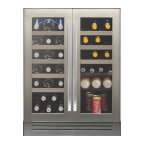
- Page 1 WI6230 Caple 60cm wine cabinet Technical information Technical information...
- Page 3 WI6230 - Caple wine cabinet Item Part Code Description DG12-37.1 Refrigerrant valve DG2-14 Power cord DG7-47 Condenser fan DG17-145-2 Electric wire DG19-3 Fan cover DG1-93 Compressor DG12-145 Start Device DG12-146 Overload Protector DG13-403 Water tank DG6-19 Transformer DG3-97-6 PCB board...
- Page 5 Computer Controlled Synchronous Dual Temperature Wine cooler JG2D1 service manual Here below we list various faults while using the wine cellar, and the method of check-up and solve these defaults, please find the information of the correspondent page. Statement:(Fig.4 ) shows the reference figure Fig4 ( →6 ) shows the reference page 6 Warning: 1.
- Page 6 ○ Sensor fault ………………………………………………………………………………..…(→9) ○ How to replace the sensor…………………………………………………………………..…(→10) ○ Refrigerant valve fault……………………………………………………………………..…(→10) ○ LED display fault ……………………………………………………………………..……(→11) ○ How to remove the parts inside the control PCB electrical box ……………..………………(→11) ○ The name and explanation of the control PCB and power PCB board connectors……………(→12) ○...
- Page 7 2>. Under the compressor is running normally, if only one zone no cooling, the fault should happen on the part in this zone.(two zones have the same structure, so the maintain method for them are same). a. Check the valve by hearing the sound. turn off the wine cooler and exchange the connectors of the valve then power on, listen carefully you can hear the snip-snap sound from valve, otherwise the valve is power off or broken or the PCB fault.
- Page 8 Fig. 1 2>. Use a Set of cross-screwdrivers to remove the air-duct board screws (Note: 1~5 are the air-duct board screws. A~D are the fan screws, need not to remove), and remove the air-duct board. Be attention to unplug the connection wire when removing the air-duct board. You can move slowly aside until you can see the fans wire, and unplug the fan connector, and then take out the whole air-duct board.
- Page 9 Fig. 3 ○ Diagram showing the front side soldered joints(Fig.3 ) A: Capillary soldered joint B: Evaporator soldered joint ○ Diagram showing the back side soldered joints(Fig.4 ) A: Compressor assistant pipe soldered jointed B: Anti-dew pipe soldered joint C: Right zone suction pipe soldered joint D: Discharge pipe soldered joint E: Left zone suction pipe soldered joint F: Condenser soldered joint...
- Page 10 ▲ Noise problem ○ Compressor noise 1>. The working of motor and piston motion will cause noise when compressor working. So if noise is steady and not exceeds 42 dB, it’s normal. If noise is not steady or very high, it’s compressor fault and it should be maintained or replaced.
- Page 11 Fig. 6 Fig. 6.1 ○ Refrigerant jet noise Fault: a continuous noise like a water spray from the capillary. Causation: the end of the capillary is in the wrong position, or there are rough edges on the end of the capillary.
- Page 12 transportation, and the oil form the jetting noise in the capillary. Solution: Clean the cooling system pipe, and recharge with refrigerant see (→2) ▲ Evaporator freezing ○ Because the gasket is not air-proof, or the door is not closed well, cause much water fill in the the cabinet, and the water got frozen when it encounter the cold air, sometimes the ice is too thick, and it will block the fan or broken the fan.
- Page 13 e. The switch controls the light functions normally. 3 >.If the above a~e point is line in the situation, and every components of the machine is normal; if there is any different, and firstly check the abnormal components and their connection wire. If the connection is tight, replace the components.
- Page 14 ○ How to replace the sensor The process of sensor removed: remove the shelves→remove the airduct board→disconnect the connectors→ remove the sensor cover→remove the sensor The sensor are fix on the airduct board(two zone are same) A. Remove the shelves. (→3) (Fig.1) B.
- Page 15 Fig. 9 ○ LED display fault This fault caused by led displayer broken,just change it will be OK. (Fig.10 & Fig.11) ○ How to remove the parts inside the control PCB electrical box (notice, the main PCB is installing in the electrical box in right zone) The process of main PCB removed: remove all the shelves in right zone→take apart the electrical box in right zone→disconnect all connectors→remove the main PCB...
- Page 16 Fig. 11 4 >.Unplug all the connecters, then press the head of each of the four plastic studs (4) one by one, and move up-ward the control board, remove the control board, and replace it with the new module. See。( Fig. 11) 5 >....
- Page 17 ○ The name and explanation of the power PCB ( Fig. 13) 1. To PTC heater (white) 2. To transformer primary (L) 3. To transformer primary(N) 4. To the main power N 5. To the main power L 6. To the compressor 7 .
- Page 18 the transformer 1 >.Remove the 2 screws (1);( Fig.14) 2 >.Remove the electrical box;( Fig.14) ,move up-ward 3>.Unplug all the connecters, then press the head of each of the four plastic screws(4) ,then replace a new one. the power PCB(A) ( Fig.14) (View K) 4>.Plug all the connecters;(Fig.13)...
Need help?
Do you have a question about the WI6230 and is the answer not in the manual?
Questions and answers