Advertisement
Table of Contents
- 1 Table of Contents
- 2 Warning Decal Placement
- 3 Important Precautions
- 4 Before You Begin
- 5 Part Identification Chart
- 6 Assembly
- 7 How to Use the Exercise Bike
- 8 How to Use the Console
- 9 Maintenance and Troubleshooting
- 10 Fcc Information
- 11 Exercise Guidelines
- 12 Part List
- 13 Exploded Drawing
- 14 Ordering Replacement Parts
- 15 Limited Warranty
- Download this manual
nordictrack.com
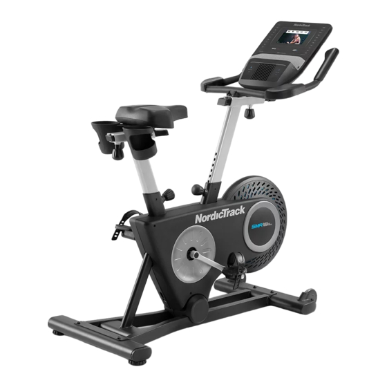
Model No. NTEX71021.0
Serial No.
Write the serial number in the space
above for reference.
Serial Number
Decal
REGISTER YOUR
PRODUCT
To register your product and
activate your warranty today,
go to my.nordictrack.com.
CUSTOMER CARE
For service at any time, go to
support.nordictrack.com.
Or call 1-800-TO-BE-FIT
(1-800-862-3348)
Mon.–Fri. 6 a.m.–6 p.m. MT
Sat. 8 a.m.–12 p.m. MT
Please do not contact the store.
CAUTION
Read all precautions and
instructions in this manual before
using this equipment. Keep this
manual for future reference.
USER'S MANUAL
Advertisement
Table of Contents

Related Manuals for NordicTrack STUDIO BIKE


Summary of Contents for NordicTrack STUDIO BIKE
- Page 1 Serial Number Decal REGISTER YOUR PRODUCT To register your product and activate your warranty today, go to my.nordictrack.com. CUSTOMER CARE For service at any time, go to support.nordictrack.com. Or call 1-800-TO-BE-FIT (1-800-862-3348) Mon.–Fri. 6 a.m.–6 p.m. MT Sat.
-
Page 2: Table Of Contents
Apply the decal in the location shown. Note: The decal(s) may not be shown at actual size. NORDICTRACK and IFIT are registered trademarks of ICON Health & Fitness, Inc. The Bluetooth ® word mark and logos are registered trademarks of Bluetooth SIG, Inc. and are used under license. Google Maps is a trade- mark of Google LLC. -
Page 3: Important Precautions
IMPORTANT PRECAUTIONS WARNING: To reduce the risk of serious injury, read all important precautions and instructions in this manual and all warnings on your exercise bike before using your exercise bike. ICON assumes no responsibility for personal injury or property damage sustained by or through the use of this product. - Page 4 STANDARD SERVICE PLANS...
-
Page 5: Before You Begin
The model number and the location of the serial number STUDIO BIKE exercise bike provides a selection of decal are shown on the front cover of this manual. features designed to make your workouts at home more effective and enjoyable. -
Page 6: Part Identification Chart
PART IDENTIFICATION CHART Use the drawings below to identify the small parts needed for assembly. The number in parentheses below each drawing is the key number of the part, from the PART LIST near the end of this manual. The number following the key number is the quantity needed for assembly. -
Page 7: Assembly
ASSEMBLY 1. To use the assembly steps in this manual, first see the helpful tips below. • Assembly requires two persons. • In addition to the included tool(s), assembly requires the following tools: • Place all parts in a cleared area and remove the one Phillips screwdriver packing materials. - Page 8 3. If there is a shipping support attached to the front of the Frame (1), remove the screws from the shipping support, and discard the screws and the shipping support. Attach the Front Stabilizer (22) to the Frame (1) with two M10 x 58mm Screws (74). 4.
- Page 9 6. Locate the Post Knob (47) on the rear of the Frame (1). Loosen and pull the Post Knob. Next, orient a Post Bushing (42) as shown, and insert it into the Frame (1). Make sure that the tabs (A) on the Post Bushing are in the holes (B) in the Frame.
- Page 10 8. If there is a shipping support attached to the Frame (1), remove and discard the shipping support. Orient a Post Bushing (42) as shown and hold it near the Frame (1). Insert the Main Wire (68) upward through the Post Bushing. Next, locate the Post Knob (47) on the front of the Frame (1).
- Page 11 10. Tip: Avoid pinching the Main Wire (68) during this step. Pull the Post Knob (47). Next, insert the Handlebar Post (6) into the Frame (1), and release the Post Knob into the lowest adjust- ment hole (G) in the Handlebar Post. Then, tighten the Post Knob.
- Page 12 12. Hold the Console Bracket (33) near the Handlebar Carriage (16). Insert the Main Wire (68) upward through the Console Bracket as Avoid pinching the shown. Main Wire (68) Tip: Avoid pinching the Main Wire (68). Attach the Console Bracket (33) to the Handlebar Carriage (16) with three M6 x 16mm Screws (72);...
- Page 13 ADAPTER on page 14. To register your product and activate your warranty today, go to my.nordictrack.com. 16. After the exercise bike is assembled, inspect it to make sure that it is assembled correctly and that it functions properly. Make sure that all parts are properly tightened before you use the exercise bike.
-
Page 14: How To Use The Exercise Bike
HOW TO USE THE EXERCISE BIKE HOW TO PLUG IN THE POWER ADAPTER How to Adjust the Seat Carriage IMPORTANT: If the exercise bike has been exposed To adjust the to cold temperatures, allow it to warm to room tem- position of the seat perature before you plug in the power adapter (A). - Page 15 HOW TO USE THE PEDAL STRAPS THE OPTIONAL HAND WEIGHTS Adjust the strap (F) To optional hand on each pedal to weights (I) will help the desired position, you add upper body and press the end exercise to your of the strap onto workouts while the tab (G) on the you pedal.
-
Page 16: How To Use The Console
HOW TO USE THE CONSOLE CONSOLE DIAGRAM FEATURES OF THE CONSOLE When you use the manual mode of the console, you can change the resistance of the pedals with the touch The advanced console offers an array of features of a button. designed to make your workouts more effective and enjoyable. - Page 17 HOW TO TURN ON THE CONSOLE HOW TO USE THE TOUCH SCREEN The included power adapter must be used to oper- The console features a tablet with a full-color touch ate the exercise bike. See HOW TO PLUG IN THE screen.
- Page 18 HOW TO SET UP THE CONSOLE HOW TO USE THE MANUAL MODE Before you use the exercise bike for the first time, set 1. Touch the screen or press any button on the up the console. console to turn on the console. 1.
- Page 19 To pause the workout, simply touch the screen HOW TO USE A FEATURED WORKOUT or stop pedaling. To continue the workout, simply resume pedaling. 1. Touch the screen or press any button on the console to turn on the console. To end the workout session, touch the screen to pause the workout, and then follow the prompts See HOW TO TURN ON THE CONSOLE on...
- Page 20 4. Start the workout. The actual number of calories that you burn will depend on various factors, such as your Touch Start Workout to start the workout. weight. In addition, if you manually change the resistance level during the workout, the number The workout will function in the same way as the of calories you burn will be affected.
- Page 21 HOW TO CREATE A DRAW-YOUR-OWN-MAP If you make a mistake, touch Undo in the map WORKOUT options. 1. Touch the screen or press any button on the The screen will display the elevation and distance console to turn on the console. statistics for your workout.
- Page 22 HOW TO USE AN IFIT WORKOUT 4. Select an iFit workout that you have previously added to your schedule on iFit.com. To use an iFit workout, the console must be connected to a wireless network (see HOW TO CONNECT TO A IMPORTANT: Before iFit workouts will load, you WIRELESS NETWORK on page 24).
- Page 23 HOW TO CHANGE CONSOLE SETTINGS 3. Customize the unit of measurement and other settings. IMPORTANT: Some of the settings and features described may not be enabled. Occasionally, a To customize the unit of measurement, the time firmware update may cause your console to function zone, or other settings, touch Equipment Info or slightly differently.
- Page 24 HOW TO CONNECT TO A WIRELESS NETWORK Note: You must have your own wireless network and an 802.11b/g/n router with SSID broadcast To use iFit workouts and to use several other features enabled (hidden networks are not supported). of the console, the console must be connected to a wireless network.
- Page 25 HOW TO USE THE SOUND SYSTEM Connect Your Headphones If the console has a headphones jack, you can plug Connect with an Audio Cable To play music or audio your headphones into the headphones jack to listen to books through the console sound system while you audio from the console through your headphones.
-
Page 26: Maintenance And Troubleshooting
MAINTENANCE AND TROUBLESHOOTING HOW TO MAINTAIN THE EXERCISE BIKE HOW TO ADJUST THE REED SWITCH Regular maintenance is important for optimal If the console does not display accurate feedback, the performance and to reduce wear. Inspect and properly reed switch should be adjusted. Before you adjust the tighten all parts each time the exercise bike is used. -
Page 27: Fcc Information
HOW TO ADJUST THE DRIVE BELT If the pedals slip while you are pedaling, the drive belt may need to be adjusted. Before you adjust the drive belt, unplug the power adapter. Next, insert a standard screwdriver under the Right Shield Ring (19) in the location shown by the arrow, and gently pry the Right Shield Ring off the Right Shield (12). -
Page 28: Exercise Guidelines
EXERCISE GUIDELINES Aerobic Exercise—If your goal is to strengthen your WARNING: cardiovascular system, you must perform aerobic Before beginning this exercise, which is activity that requires large amounts or any exercise program, consult your physi- of oxygen for prolonged periods of time. For aerobic cian. -
Page 29: Part List
PART LIST Model No. NTEX71021.0 R0421A Key No. Qty. Description Key No. Qty. Description Frame M8 Split Washer Power Wire/Receptacle Left Pivot Cover Seat Post Post Knob Seat Carriage Wheel Spacer Seat Hand Weight Rest Handlebar Post Right Grip Handlebar M4 x 22mm Screw Water Bottle Holder M4 x 10mm Screw... -
Page 30: Exploded Drawing
EXPLODED DRAWING A Model No. NTEX71021.0 R0421A... - Page 31 EXPLODED DRAWING B Model No. NTEX71021.0 R0421A...
-
Page 32: Ordering Replacement Parts
ORDERING REPLACEMENT PARTS To order replacement parts, please see the front cover of this manual. To help us assist you, be prepared to provide the following information when contacting us: • the model number and serial number of the product (see the front cover of this manual) •...
Need help?
Do you have a question about the STUDIO BIKE and is the answer not in the manual?
Questions and answers
My touch screen has an > and a box that says retry. I can't get anything to come up on the screen
I think my granddaughter running around pulled the cord out of the bike and it Broke the black ring that the cord goes into
To replace the broken black ring (Right Shield Ring) on a NordicTrack Studio Bike after the cord was pulled out, follow these steps:
1. Use a standard screwdriver to gently pry off the Right Shield Ring in the location indicated by the arrow in the manual.
2. Remove the Right Shield if necessary.
3. If the pedals are slipping, slightly tighten the Idler Adjustment Screw.
4. Plug in the power adapter and pedal the bike briefly to check for slipping.
5. Repeat the adjustment until the pedals no longer slip.
6. Reattach the Right Shield Ring securely.
Make sure to follow all safety precautions while performing these steps.
This answer is automatically generated