Table of Contents
Advertisement
Quick Links
Advertisement
Table of Contents
Troubleshooting

Related Manuals for Canon Arizona 2300 Series


Summary of Contents for Canon Arizona 2300 Series
- Page 1 Arizona 2300 series Operation guide © 2020-2022 Canon Production Printing...
- Page 2 Original instructions that are in American English. Trademarks Canon is a registered trademark of Canon Inc. Arizona, VariaDot are trademarks or registered trademarks of Canon Production Printing Netherlands B.V. Adobe, Illustrator, Photoshop, PostScript, and the Adobe logos are either registered trademarks or trademarks of Adobe Systems Incorporated in the United States and/or other countries.
- Page 3 Security is about safeguarding communication and data and keeping our online society and economy secure. It is critical for our customer’s business and we take it seriously at Canon Production Printing. Security is incorporated in the early stages of our product development process.
- Page 4 1. Name and version of the Canon Production Printing software you licensed. 2. Name and version of open source software modules contained in the above identified Canon Production Printing software of which you legitimately would like to obtain the source code.
-
Page 5: Table Of Contents
Contents Contents Chapter 1 Introduction.........................9 Notes for the reader............................10 Available documentation and training......................12 Printer Specifications............................. 14 Chapter 2 Safety Information......................15 Safety and Environment Information......................16 Flush................................27 UV LED Curing System ..........................28 Safety Interlock System..........................29 Safety Awareness............................30 Roll Media Safety Awareness........................36 Chapter 3 Navigate the User Interface..................... - Page 6 Contents Hardware.................................92 Specifications..............................94 Foot Pedal Switch Functions......................... 95 Roll Media Manager............................96 Load Media..............................98 Load Media - Standard Method......................100 Load Media: Alternate Method ......................105 Unload and Remove Media......................... 108 Set Up a Roll Media Job..........................110 Set a Hold on a Roll Job........................110 Print on Roll Media............................112 Determine the Media Step Correction Factor....................
- Page 7 Contents Shutdown Procedure..........................183 Printer Maintenance............................. 184 Clean Horizontal Surfaces........................184 Clean the Automatic Maintenance System (AMS) ................185 Clean the Ink Spit Tray ..........................187 Clean the Carriage Underside....................... 188 Maintain White Ink..........................189 Clean Printheads............................ 190 Replace the UV LED unit Filter......................193 Remove Ink from the Table........................
- Page 8 Contents...
-
Page 9: Chapter 1 Introduction
Chapter 1 Introduction... -
Page 10: Notes For The Reader
Names of options to be used in a fixed order Safety symbols Before you use this product, make sure you read and understand the safety information that "https://downloads.cpp.canon" belongs to the product. Find the safety information on . Also be sure to follow all warnings and instructions marked on the product. - Page 11 Notes for the reader Symbol Type of symbol Indicates CAUTION Laser beam Indicates a caution concerning operations that may lead to in- jury to persons if not performed correctly. To use the ma- chine safely, always pay attention to these cautions. IMPORTANT Indicates an operational requirement or restriction.
-
Page 12: Available Documentation And Training
Available documentation and training Available documentation and training This manual provides the operator with information about the following Arizona 2300 series UV flatbed inkjet printers: • Arizona® 2340 GTF/XTF • Arizona® 2360 GTF/XTF • Arizona® 2380 GTF/XTF Multi-Language Support The printer's user interface software supports multiple languages. To select your preferred... - Page 13 Available documentation and training Representative Manufacturing and Marketing for the Arizona 2300 series in Europe: Canon Production Printing Netherlands B.V. Van der Grintenstraat 10, 5914HH Venlo The Netherlands Telephone: 31 77 359 2222 Fax: 31 77 354 4700 Email: info@cpp.canon...
-
Page 14: Printer Specifications
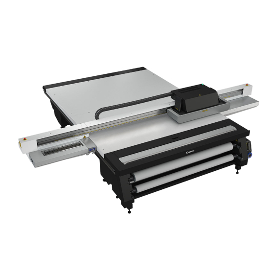
Printer Specifications Introduction Your Arizona 2300 series printer is capable of producing large format images on various rigid and flexible media. The printers consist of a flatbed vacuum table and moving gantry. Media is held flat and stationary on the vacuum table during printing. The gantry contains a carriage that sweeps across the table as the gantry moves in steps along the length of the table to print an image on the media. -
Page 15: Chapter 2 Safety Information
Chapter 2 Safety Information... -
Page 16: Safety And Environment Information
The websites of the regional Canon sales offices are listed on the cover of the User Documentation. There you can find the addresses of the local Canon sales offices. - Page 17 If applicable, the relevant CE Declaration of Conformity is part of the User Documentation. You "http://downloads.cpp.canon/" may also download it from the support site of your product at Canon Production Printing shall not be liable for damages from: • Failure to comply with the User Documentation; • Work performed incorrectly on the machine;...
- Page 18 Safety and Environment Information Symbol Type Description NOTE Indicates a clarification of an operation, or contains additional explanations for a procedure. Reading these notes is highly recommended. If applicable the following Prohibited indicators are used in the User Documentation: Label Type Description PROHIBITED...
- Page 19 Safety and Environment Information Label Type Description Caution Optical radiation: Take care to avoid injury to eyes and skin when in the vicinity of optical radiation. Warning Electricity: Protective Earth (PE) terminal which is intended for connection to an external grounded conductor for protec- tion against electric shock in case of a fault.
- Page 20 Safety and Environment Information Label Type Description WARNING General warning. Moving gantry. Stay clear. Translation: Moving Gantry WARNING Warning: Electricity. Residual voltages present after power down or disconnecting the mains voltage. Please wait 10 seconds before opening panels or covers. Translation: Residual voltages present af- ter power down.
- Page 21 Safety and Environment Information Persons for Machinery according Directive 2006/42/EC • Instructed person This User Documentation describes safeguards for the protection of an instructed person. Instructed person is a term applied to persons who have been instructed and trained by a skilled person, or who are supervised by a skilled person, to identify energy sources that may cause pain and to take precautions to avoid unintentional contact with or exposure to those energy sources.
- Page 22 Safety and Environment Information Installation WARNING • The machine may be transported, assembled, installed, moved and repaired only by an authorized service representative. • The installation of accessories and options not permitted for the machines may constitute a violation of the Safety Regulations and Directives, and can also damage the machine. •...
- Page 23 Safety and Environment Information CAUTION • This equipment is not suitable for use in locations where children are likely to be present. IMPORTANT • Unplug the product when you are not going to use the product for a long period of time. Maintenance, repair and modification WARNING •...
- Page 24 Poisonous gases can be produced in any fire. They can also result from a fire in this machine. Keep into account: Canon Production Printing systems are designed in such a way that fire is encapsulated within the enclosure, thus preventing the further spread of fire to the customer’s premises.
- Page 25 • Avoid skin contact with ink and uncured printed media. • Curing of media of the Canon Production Printing supported media-list is tested and considered sufficient under standard conditions. • After a printer error, wear gloves to handle the unfinished print.
- Page 26 Disposal of parts WARNING • All parts are produced according to the sustainability policy of Canon Production Printing. You can discard all used parts into a common dustbin, or follow your local or national sustainability and waste disposal procedures.
-
Page 27: Flush
Flush Flush Flush Care and Storage A small bottle (125ml) is supplied with the printer accessory kit. Use it only to hold flush. Before first use, proceed as follows: Label this bottle as "Flush", add the actual date of receipt of the bottle and the date of expiry (two years after receipt). -
Page 28: Uv Led Curing System
Provide adequate ventilation as indicated in the Product Safety Data Sheet (PSDS) of the printer. You can download the current and valid PSDS from the support site of your product at http://downloads.cpp.canon/ Personal Safety WARNING Wear UV safety glasses that reduce harmful UV and blue light below local exposure limits in the wavelength range of 365 nm –... -
Page 29: Safety Interlock System
Safety Interlock System Safety Interlock System Introduction The printer has three Emergency-Stop switches. The Maintenance Station drawer is part of the safety interlock system. A beacon light indicates the status of the safety system and the printer. Components of the Interlock System Emergency Stop Buttons: These are located on the Operator Control Station, and on each end of the Gantry. -
Page 30: Safety Awareness
Safety Awareness Safety Awareness Introduction This section contains two sets of principles that must be followed to assure maximum safety when operating your Arizona printer. The first set uses negative examples to show you things to avoid in order to prevent injury to the operator. The second set of principles illustrates some of the residual risks that are inherent in the operation of the printer. - Page 31 Safety Awareness Avoid these Situations For Your Personal Safety Do not push or force the gantry to move manually if it is already in mo- tion. If you do move the gantry, a Mo- tion Error message will display and you will have to use the mouse to click Reset on the user interface LCD dis- play.
- Page 32 Safety Awareness Avoid these Situations For Your Personal Safety Avoid placing fingers, hands or other objects in the IGUS track unless power is off and the printer is locked out. [6] IGUS Hazard Avoid printing at a height greater than measured as this causes excessive emissions of UV light and ink mist.
- Page 33 Safety Awareness Arizona Printer Residual Risks Hazard Residual Risk Area A high risk crushing hazard is created by the movement of the carriage and gantry supports. Keep hands away from this area unless the printer power is off. [8] Carriage guard and 45° guard on Gantry Supports A crushing hazard is created by the movement of the carriage along gantry rails.
- Page 34 Safety Awareness Hazard Residual Risk Area A high risk crushing/pinch hazard is created by the carriage and the gantry when the Z-Axis is moving (carriage moves up or down). [11] Carriage Vertical Movement Pinch Hazard A high risk shearing hazard is created by the gantry and the gantry rail.
- Page 35 Safety Awareness Hazard Residual Risk Area Entanglement hazard A medium risk of finger or material en- tanglement is created by the web as- sembly (IGUS track). [14] IGUS Impact Hazard A medium risk impact hazard is cre- ated by the carriage when cycling from left to right.
-
Page 36: Roll Media Safety Awareness
Roll Media Safety Awareness Roll Media Safety Awareness Introduction This section contains two sets of principles that must be followed to assure maximum safety when operating the Roll Media Option (RMO) for your Arizona printer. The first image uses a negative example to show you a situation to avoid in order to prevent injury to the operator. - Page 37 Roll Media Safety Awareness Crushing/Shear Hazard Residual Risk Area Do not place your hand near the shaft drive motors when the printer is print- ing or when the dual foot controls are pressed. Do not place your hand on the Media Roll motor enclosure when the green beacon light is On as the gantry may move at any time.
- Page 38 Roll Media Safety Awareness Chapter 2 - Safety Information...
-
Page 39: Navigate The User Interface
Chapter 3 Navigate the User Interface... -
Page 40: Operator Interface Hardware
Operator Interface Hardware Operator Interface Hardware Introduction The Operator interacts with printer components to print, maintain, and monitor the state of the printer. This section identifies and explains the functions of the hardware. Operator Interface Components Hardware Interface Components Component Function 1) Main Power Switch Turns the printer On and Off. - Page 41 Operator Interface Hardware Component Function 10) Registration Pins Allow the operator to register media by placing it against the pins. Registration pin operation can be set at the user interface to work in either manual or automated mode. Pins can be enabled or disa- bled individually.
-
Page 42: Printer Interface Software
Printer Interface Software Printer Interface Software Introduction The printer software is displayed on the LCD monitor. The interface has seven main modules that are accessed by tabs located at the bottom of the display. Click on these tabs to access the modules. - Page 43 Printer Interface Software Component Function Maintenance Displays maintenance tasks you must perform and indicates when to (Maintenance tab) do them. After you perform each task, the printer will record that the task was completed and then calculate when the task must be per- formed again.
-
Page 44: Print Job Control Module
Print Job Control Module Print Job Control Module Introduction Print Job Control is the first module displayed when the printer software is loaded. From this module, you can manage all aspects of working with print jobs and also control many features of the printer. - Page 45 Print Job Control Module Component Function 6) Active Jobs List Displays a list of all Active print jobs. 7) Job Placement Displays the selected print job with a preview that shows the place- Preview ment of that job on the printer 8) Archived Jobs Displays a list of all archived print jobs (they will remain in the list until deleted).
- Page 46 Print Job Control Module [17] Command Toolbar Command Toolbar Icons Explained Print job This command can do the following actions depending on context: • Activates a selected inactive job by moving it to the active list. • Un-holds a held job. •...
- Page 47 Refer to Customer Application Bulletin 45 "Batch Mode Operation" on our website https://graphiplaza.cpp.canon for more details and examples. Ink Temperature This icon switches the ink heater on or off and also displays the ink temper- Control ature.
- Page 48 Print Job Control Module Move Gantry Moves the gantry from its parked position to the center of the table. Start This icon can be used to start a flatbed print job (same function as the physical button on the table). Nozzle check This icon populates the active job list with a job that prints a nozzle check pattern.
- Page 49 Print Job Control Module 7) Job Placement Preview The table placement preview shows the print location and a proportional representation of the image in relation to the table. The zoom button in the bottom right corner activates a popup preview window. If a preview image is not available, an appropriately sized white box is used as a placeholder, and the zoom button is not displayed.
- Page 50 Print Job Control Module Offsets To change parameter values, click on the field and this brings up an onscreen keyboard so you can click on the numbers required. You can also use Preview to drag an image to the desired position. Position on media - No: •...
- Page 51 Print Job Control Module Magenta inks in pallet to work. As a result, this mode is only available when using the optional eight color ink configuration (CMYKcmWW/WV). Available with the Arizona 2380 model only. • Quality provides excellent image quality and is suitable for a wide range of image types and looks good with most media.
-
Page 52: Maintenance Tasks
• Use the cleaning methods and the maintenance schedule documented in this User manual, the Care and Use Poster, and the Printhead Maintenance video (you can download the poster and video from the customer support website: https://graphiplaza.cpp.canon. Illustration Chapter 3 - Navigate the User Interface... -
Page 53: Counters Module
Counters Module Counters Module Introduction The Counters module displays counters that are of interest to the operator. It shows counters for each color of ink and the total ink used. Some of the counters can be reset. Counters Component - function table Counters Explained Component Function... - Page 54 Counters Module Component Function Printed Area A measurement of the total media printed to date. This counter includes the area covered by special prints, and the partial area covered by cancel- led prints. Overprints are ignored, as they do not consume new media. Display shows measurement in each possible printer configuration (flat- bed/roll to roll) and an overall total.
-
Page 55: Settings Module
Settings Module Settings Module Introduction The Settings Module allows you to review and change the date and time, network connection settings, user interface configurations, printer settings and, if installed, the Roll Media settings. Date and Time Settings • Date - display only, cannot change the date •... - Page 56 Settings Module • IP Address • Subnet Mask • Default Gateway • [HTTPS proxy] • [HTTPS proxy authentication] NOTE A network name for the printer cannot consist of numeric characters only - it must be a mix of alpha-numeric characters. If the Printer name is changed, the printer must be restarted for the change to take effect.
- Page 57 Settings Module Printer Settings Allows you to set the following: • Underlay thickness • Table vacuum timeout • Ionizer bar (static suppression - On or Off) • Beep on print • Media registration pins behavior • Enable/disable media registration pins •...
- Page 58 Settings Module Roll Module Top Margin Specifies the distance to be left not printed above the image. Bottom Margin Specifies the distance to be left not printed below the image. Media Move on Unload Specifies the amount of media moved on unload in the selected measurement units. NOTE This setting icon is displayed only if the Roll Media Option is installed.
-
Page 59: Tools And Utilities Module
Tools and Utilities Module Tools and Utilities Module Introduction The Tools and Utilities Module has three sub-modules: Special Prints, Shutdown, and the System Logs. When you click on the Tools tab, Special Prints always appears first. Click on the other icons to access the sub-modules. - Page 60 Tools and Utilities Module The list on the top shows all active jobs that are currently in the print queue. Add a special print from the bottom to make it active in the Print Job Control module. If you remove a job from this list, it is also removed from the Active job list and is not available to print.
- Page 61 Tools and Utilities Module second batch if you have just recently generated log files (unless requested to do so by a service technician). Chapter 3 - Navigate the User Interface...
-
Page 62: Software Update Module
Your dealer or service representative will advise you when an update of the printer software is necessary. If they request that you install the upgrade, an unzip password will be provided and instructions are available from our website https://graphiplaza.cpp.canon when the update file is downloaded. -
Page 63: Chapter 4 Operate The Printer
Chapter 4 Operate the Printer... -
Page 64: Training Requirements
The operator must receive training for safety issues, printer operation, and the appropriate ONYX Thrive software prior to operating the printer. Safety training Before operating the Arizona 2300 series printer, make sure you have read and understood all of chapter Safety Information. Operator Training For optimal safety and print quality, all printer operators must have received training by qualified service personnel. -
Page 65: Printer Power On And Off
Printer Power ON and Off Printer Power ON and Off Introduction It is critical for the printer to remain powered ON at all times. Power is required in periods of inactivity so the printer can perform automatic functions to maintain its operating state. If these functions do not take place, damage to critical components can occur. -
Page 66: Manage The Flow Table
Manage the FLOW Table Manage the FLOW Table The table layout Zone B Zone A Label Hardware Description Print Start Button Vacuum Gauges Print Origin There is a left origin and a right origin for every zone. The GTF has one zone, the XTF has two zones. -
Page 67: The Table Vacuum System
The Table Vacuum System The Table Vacuum System Introduction The printer uses vacuum to secure media to the printer table. The GTF table has one vacuum zone, the XTF has two vacuum zones. The table makes it possible to put media on the table without masking the vacuum holes. -
Page 68: Set The Vacuum Level For The Flow Table
Set the vacuum level for the Flow table Set the vacuum level for the Flow table Introduction Via the operator panel the operator sets the vacuum pressure. The system automatically controls the blowers for reaching the corresponding pressure. The operator sets the vacuum pressure on the operator panel, which depends on the media type. Level Pressure Info... - Page 69 Set the vacuum level for the Flow table Procedure 1. Click on the Vacuum Settings icon 2. Select the level per zone. 3. To activate the vacuum click on the icon on the command bar of the Print Job module or with the foot switch on the floor.
-
Page 70: Media Registration
Media Registration Media Registration Introduction Media can be registered on the table using the built-in registration pins and the table rulers. The registration pins can be linked to the vacuum switch or activated manually by the operator to allow quick registration of the media to the printer origin. The rulers are printed on the table and provide a horizontal and vertical rule that originate from the 0,0 print origin points on the table. - Page 71 Media Registration IMPORTANT Do not slide heavy media into the pins with excessive force. Media with abrasive edges can damage the pins - handle carefully. Ink contamination can cause pins errors (see Pin Maintenance section below for cleaning tips). Setting Registration Pin Behavior for GTF Printers You can set the behavior of the registration pins and also determine which of the pins are active in the Settings tab.
- Page 72 Media Registration Origins The table has two origins per zone, one on the left and one on the right. In the printer software you can decide which origin will be used to define the offset values. Registration Pin Error Handling Three Levels of Safety: 1.
- Page 73 Media Registration Registration Pin Maintenance During a print job with a bleed, ink will deposit on the top surface of the pins and pin housings. The accumulation of ink on these surfaces should not grow beyond the top surface of the overlay. When this occurs remove the accumulated ink by using a razor blade or scraper on the top surface of the overlay only (with pins in the down position).
-
Page 74: Print Rulers On The Table
Introduction The printer software provides various rulers to be printed on the table. The table rulers are also available for download from our website: https://graphiplaza.cpp.canon Available rulers The versions below are available for metric and imperial, for GTF and XTF. -
Page 75: Print A Job
Print a Job Print a Job Print workflow The basic steps to follow for printing a job: Prepare a Digital Image with ONYX Thrive Operator must be trained to use ONYX Thrive. Training is provided by ONYX. Send the Job From ONYX Software to the Printer When the job is sent from the ONYX software, the job transmission progress is indicated in the lower right corner of the User Interface display. - Page 76 Print workflow If the media is dusty or dirty, clean it with an appropriate cleaner. If using a liquid like isopropyl alcohol, allow sufficient time to dry prior to imaging. Start Print The physical Print button is located at the corner of the table where media is loaded and a Start print is also available in the UI.
-
Page 77: Batch Mode Printing
Batch Mode Printing Batch Mode Printing Introduction Batch mode printing is available for streamlining multi-layered jobs for specialty applications or facilitating set collation of multiple images on one piece of media. Individual print jobs are sent from the RIP to the printer, and then combined on the printer to create a batch job for flatbed printing. - Page 78 Batch Mode Printing 2. Select the Create Batch icon to open the batch editor. 3. Provide a name for the batch job in the Batch name: field. 4. Select the Batch type: either Composite or Collation Enabling composite Make sure your settings are correct for printing a Composite batch job. See batch job nesting on page 80 5.
- Page 79 Batch Mode Printing 6. Use the mouse to place the selected images within the rectangle that represents the media in the Preview pane. NOTE Placement of images can be changed at any time by editing the batch job or by clicking the + to the left of the batch job name, selecting one of the included images, and then moving that image with the mouse.
-
Page 80: Enabling Composite Batch Job Nesting
Enabling composite batch job nesting Enabling composite batch job nesting Introduction To increase productivity you can automatically print composite batch jobs in a single print. This is possible when the following conditions are met: • All member jobs use the same print mode. •... -
Page 81: Print With Dual Origins
Print With Dual Origins Print With Dual Origins Introduction Due to the larger table size and the vacuum zone arrangement of the Arizona 2300 XTF printer, it is possible to print in an alternating 2-up arrangement using Origin A and Origin B for placement of the image. - Page 82 Print With Dual Origins Procedure 1. Add your image to the active print job queue and then select it. 2. Enter 2 or more copies in the Job Parameters Copies field. 3. Click on the Origin pull-down menu and select Dual Origin to make it active. NOTE When Dual Origin is selected, a scaled view of the image appears on the screen preview in Zone A and a bounding box that represents the image appears in Zone B.
-
Page 83: Step And Repeat Printing
Step and Repeat Printing Step and Repeat Printing Introduction Step and Repeat Printing allows the operator to define a grid and place an image in each cell to print multiple copies. The operator selects the number of rows and columns desired and the number of copies needed and the copies of the image are positioned in each cell of the grid. - Page 84 Step and Repeat Printing 3. Fill in the Rows and Columns fields by either clicking on the upward pointing triangle or within the field to use the virtual keypad that appears. NOTE You can also click on the Fill area... button to have the grid created automatically based on the dimensions of the image, the size of the media, and the number of copies.
-
Page 85: Print Multiple Copies Side By Side
Print multiple copies side by side Print multiple copies side by side Introduction For the most productive use of the table, multiple copies are printed side-by-side. In this scenario we are printing many copies of the same job, each on their own piece of media. The operator wants to get the same image-to-media position for all copies. - Page 86 Print multiple copies side by side 6. Place new panels on the table and start printing. Repeat this until all copies are printed. NOTE In this simulation we only use one zone. For the XTF you can use dual origin. You can Print With Dual set up the panels in zone B for a more productive use of the table.
-
Page 87: Duplex Printing
Duplex printing Introduction The Arizona 2300 series table layout provides features to help you print double sided. The table has an origin left and an origin right per zone. Also the registration pins are on the left and on the right side. - Page 88 Duplex printing Front side Back side For the alignment of the panel in the right corner, select: From the right. Keep the Media distance and Image alignment on media identical. Set the Media horizontal distance to 0 mm. NOTE When you switch to From the right, the placement stays the same. The Media horizontal distance value changes.
-
Page 89: How To Handle Media
How to Handle Media Introduction Canon Production Printing has conducted extensive testing of many media. Since your printer is capable of imaging on a wide range of material, we encourage you to explore various media so that you can establish your own criteria for achieving high quality images in your work environment. - Page 90 Tack cloths are used by auto-body shops to clean cars before painting. Canon Production Printing does not provide additional tack cloths beyond what is in the Accessory kit. If you did not receive a cloth or if you wish to purchase additional tack cloths, they are available at local hardware or auto supply stores.
-
Page 91: Chapter 5 Roll Media Option
Chapter 5 Roll Media Option... -
Page 92: Hardware
Hardware Hardware Introduction The Roll Media Option (RMO) allows printing on media that is supplied on a roll. Component Locations Roll Media Hardware Component Component 1) Dual Foot Pedal Switches 6) Media Access Door 2) Media Drive Couplers 7) Media Cut Guide 3) Accessory Holder 8) Media Tension Bar 4) Take-up Media Shaft... - Page 93 Hardware Component Function 2) Media Drive Cou- Keeps the media shafts in place and engaged to the drive motor. In the plers open (horizontal) position they allow the media shafts to be removed. 3) Accessory Holder Stores tape, cutting blade and 5mm hex key tool. 4) Take-up Media Supports the take-up media roll.
-
Page 94: Specifications
Specifications associated with the use of roll media are indicated in this section. NOTE The Roll Media Option must be operated in accordance with the environmental conditions specified in the Arizona 2300 series Site Preparation Guide and all safety requirements noted in this document. Media Size Supported Width (Max.): 2.2m (86.6") -
Page 95: Foot Pedal Switch Functions
Foot Pedal Switch Functions Foot Pedal Switch Functions Introduction The foot pedal switches are used to control the forward and reverse movement of media shafts. Summary of Dual Foot Pedal Switch Functions The following table indicates the foot pedal functions for various RMO states. Actions for foot pedals in various states Media Reverse Media Forward... -
Page 96: Roll Media Manager
Roll Media Manager Roll Media Manager Introduction The Roll Media Manager is the area of the printer software where you prepare to print on roll media. With this menu you can load and unload media, change media type and parameters, and initialize the printer to prepare it to print on roll media. - Page 97 Roll Media Manager Icon Function Initialize Sets up tension on the loaded media and prepares the RMO to print on that media. Print Side Operator can select either Print Side In or Print Side Out. Print Side In allows you to print on the back side of the media. The default setting is Print Side Out.
-
Page 98: Load Media
Load Media Load Media Introduction This section details the following actions that are associated with loading media: • A) Load Supply Media Roll On Media Shaft • B) Load Take-up Empty Core On Media Shaft • C) Loading the Media - Standard Method •... - Page 99 Load Media It is very important that the media is wound properly onto the core when it arrives from the manufacturer. The media must be wound straight, tight and even from one end to the other. If you have a roll that is not even, before loading it, hold the roll in a vertical position and carefully and evenly drop one end onto the floor, then tap lightly a few times.
-
Page 100: Load Media - Standard Method
Load Media - Standard Method 5. Accurately center the media using the supplied ruler. Media should be centered within 1mm on the ruler. [23] Ruler to Center Media NOTE The supplied ruler has both metric (millimeters) and imperial (inches) scales. When a media roll is centered on the shaft, and the ruler is placed as shown in the photo, the value on the ruler scale will match the width of the roll. - Page 101 Load Media - Standard Method 2. If you are going to print with "Print Side In", click the icon in the Roll Media manager ("Print Side Out" is the default so you do not need to select it unless you have previously used Print Side In). Note that the icon toggles from one choice to the other when you click it.
- Page 102 Load Media - Standard Method 6. Reach down through the open door to grasp the media and feed it up and over until it reaches the take-up roll. [26] Feed Media Through Access Door Chapter 5 - Roll Media Option...
- Page 103 Load Media - Standard Method 7. Check alignment of the media by feeding it down to the supply roll and make sure that the edge lines up with the edge of the supply roll. [27] Align Media 8. Rewind the media by continually pressing down the left foot pedal until it is positioned where it can be taped to the take-up core.
- Page 104 Load Media - Standard Method 9. Tape the media onto the core. The media should have a clean straight edge prior to taping. First tape the center of the media to the core, and then tape both ends of the media. [29] Tape Media to the Take-up Roll Core NOTE Important: Use the supplied ruler to check that the edge of the take-up roll is aligned...
-
Page 105: Load Media: Alternate Method
Load Media: Alternate Method Load Media: Alternate Method This alternate method to load media requires a little more time and effort but it usually provides better alignment and therefore less chance of banding in the image. When roll media is not properly aligned, the result is overstepping on one side and under-stepping on the other side of the media so that the band in the printed image is dark on one side and light on the other. - Page 106 Load Media: Alternate Method 4. Pull the hanging media edge taut and cut the media off from each edge at an angle to result in a point just below the take-up core as shown here. [31] Cut the media at an angle 5.
- Page 107 Load Media: Alternate Method 6. Remove the tape you used to hold the media to the platen. [33] Remove Tape 7. Select the "Initialize" icon from the Roll Media Manager to prepare the RMO for printing. 8. After initialization has completed, advance the media until the cut area is wound onto the core across the width of the roll and verify with the ruler that the supply and take-up edges are at the same location.
-
Page 108: Unload And Remove Media
Unload and Remove Media Unload and Remove Media Introduction This section explains all of the actions associated with how to cut and unload media when there is still some media left on the supply roll. Unload Media Summary The following actions are associated with unloading media: •... - Page 109 Unload and Remove Media Result The media is removed and you can now add a different media to the shaft. Chapter 5 - Roll Media Option...
-
Page 110: Set Up A Roll Media Job
Set Up a Roll Media Job Set Up a Roll Media Job Introduction Print jobs can be specified as either a roll job or a flatbed job in the ONYX workflow software. The job type can be changed after the print job is transferred to the printer. Purpose The operator can choose the type of desired print job and also put a hold on it so it will not print automatically. - Page 111 Set a Hold on a Roll Job [35] ONYX Roll Hold NOTE The Hold for operator is not selected in this illustration since the box is unchecked. If you want to initiate a hold, click it to select. Chapter 5 - Roll Media Option...
-
Page 112: Print On Roll Media
Print on Roll Media Print on Roll Media Introduction To print an RMO image, media must be loaded and the RMO initialized. Use the Print Job module and the Roll Media Manager to prepare and start the print job. How to Print on Backlit Media If your roll media is transparent or opaque and you are going to backlight the image and you want to increase the density, set Quality mode in ONYX Thrive. - Page 113 Print on Roll Media 3. Click on the Roll Manager icon to enter the Roll Media Manager dialog window. 4. Enter the Media width for the roll media that you have loaded. NOTE If the media width entered is less than 1067 mm (3.5 ft), the standard nozzle check will not fit across the media.
- Page 114 Print on Roll Media NOTE There is always at least one media in the list that is called Default Media. It cannot be deleted, but you can change its parameters if you want to use it. If you choose to delete it, the parameters will go back to its original values, but the item will still appear in the list.
-
Page 115: Determine The Media Step Correction Factor
Determine the Media Step Correction Factor Determine the Media Step Correction Factor Introduction When you print on roll media, there can be discrepancies in the amount the media advanced during each print swath. This is referred to as media stepping. It can cause banding to occur, in the form of either dark lines or white gaps. -
Page 116: Media Edge Protectors
Media Edge Protectors Media Edge Protectors Introduction Some media tend to have dust and fiber that clings to the edge of the media roll. When released near the RMO (Roll Media Option) unit platen, these particles can find their way into the printhead nozzles and cause dropouts that reduce image quality and produce banding. - Page 117 Media Edge Protectors 3. Bend the height adjustor (small triangle in the top corner of the edge protector) slightly and then straighten it again. This results in a slight bend (no more than a media thickness), that allows the media edge to move more freely under the protector. [38] Media Edge Detector Height Adjustor IMPORTANT If the height adjustor area is higher than 1 mm from the platen, there is a possibility that...
- Page 118 Media Edge Protectors Result The media edge protectors will reduce the amount of fiber and other debris. However, it is important to keep the platen and cutting guide areas clean as indicated in the Roll Media maintenance section. How to Deal with Wide Media If you use media of the maximum width for the RMO (2.2m or 7.2 feet) that requires media edge protection, you can cut the protectors in half in order for them to fit.
-
Page 119: Static Suppression Option
Chapter 6 Static Suppression Option... -
Page 120: Reduce Static With The Static Suppression Option
Reduce Static with the Static Suppression Option Reduce Static with the Static Suppression Option Introduction The Static Suppression Option (sometimes referred to as an Ionizer Bar) is a Commercial Product. If you are experiencing static-related imaging problems this optional upgrade kit contains an ionizer bar that provides a solution to reduce static. -
Page 121: How To Change The Height Of The Bar
How to Change the Height of the Bar How to Change the Height of the Bar The Ionizer bar is mounted by default to accommodate media up 13mm (0.5 inches) in height. If you need to use media that has a thickness of greater than 13mm you will have to reverse the mounting brackets. - Page 122 How to Change the Height of the Bar 5. Slide the bracket mount until the screw is located in the smaller end of the keyed slot. [42] Bracket Mounted High 6. Make sure the bracket is level an then tighten the bracket mount screw. 7.
-
Page 123: Manage A White Ink Workflow
Chapter 7 Manage a White Ink Workflow... -
Page 124: Operator Guidelines For White Ink
Operator Guidelines for White Ink Operator Guidelines for White Ink Introduction This chapter is necessary only if your printer has the white ink option. Managing White Ink White ink is re-circulated in the system to limit any settling of the ink. For this to take place, the printer must be left powered on at all times. -
Page 125: White Ink Workflow Overview
White Ink Workflow Overview White Ink Workflow Overview Introduction Arizona printers with the White Ink Option provide under-printing for non-white media or objects, over-printing for backlit applications on transparent media and/or printing white as a spot color. When working with white ink there are three data layers available that allow you to determine the area the white ink will cover and also how it will appear (or not appear) in relation to other colors, depending on the layer it is placed in. - Page 126 White Ink Workflow Overview Printer Flood Fill Layer Configuration in an ONYX workflow does not require any pre-rip file preparation and is the easiest method of achieving white ink output. All that is required is to set up the Layer Configuration to include a printer flood layer. The printer flood layer encompasses the bounding box (the outer border of the image) of the file being processed.
- Page 127 White Ink Workflow Overview The backlit application involves printing onto a transparent or translucent material and mounting the finished piece onto a light box or location where illumination from behind is possible. In the backlit application, white ink is intended to provide a light diffusing layer. This application is possible using either 2 or 3 layers.
-
Page 128: Varnish Workflow Overview
Varnish Workflow Overview Varnish Workflow Overview Introduction Arizona printers with the Varnish Option can overprint varnish on top of a printed image in selected areas in a print job or as a flood coat. The printing of varnish applies only to flatbed printing and is not available with the RMO. - Page 129 Varnish Workflow Overview White Spot Data Image Preparation requires that the varnish data be prepared in image editing programs such as Adobe Illustrator®, InDesign, or PhotoShop®. You must use specific naming conventions and image use protocols in order for the ONYX RIP-Queue software to process the data as desired.
-
Page 130: Configure Onyx Thrive For White Ink
Configure ONYX Thrive for White Ink Configure ONYX Thrive for White Ink Introduction This section describes how to configure ONYX Thrive to recognize white ink workflow elements and thus allow you to apply the approach that is best for your print job application. In order for the ONYX Thrive software to successfully address white ink workflow data, there are options in the software that must be configured. -
Page 131: White Ink Onyx Media Profiles
White Ink print jobs require media profiles with a particular ink configuration and spot colors defined. Media profiles for your printer are available from our website: https:// graphiplaza.cpp.canon White Ink ONYX Media Profiles Arizona Quality-Layered print mode is used to print white ink applications such as under-printing... - Page 132 White Ink ONYX Media Profiles NOTE When printing white ink using print modes other than Quality-Layered, it is not recommended to print white ink in the same area of an image as CMYK inks. The white ink does not mix well with the other ink colors.
-
Page 133: Prepare White Ink/Varnish Print Jobs
Prepare White Ink/Varnish Print Jobs Prepare White Ink/Varnish Print Jobs Select the Best Workflow Introduction When working with white ink you can choose the workflow that best fits your needs. There are three main approaches to white ink workflow with your printer: •... -
Page 134: Set Up A Printer Flood Fill
Set Up a Printer Flood Fill Set Up a Printer Flood Fill Prepare a Printer Flood Fill With the Printer Flood Fill approach, white ink is set up as a layer that is embedded in the print job. Purpose The Printer Flood Fill mode allows you to print an image with a white flood fill as an underlay or an overlay. -
Page 135: Create Spot Data With The Spot Layer Tool
Create Spot Data with the Spot Layer Tool Create Spot Data with the Spot Layer Tool Introduction The Spot Layer Tool can be used to set up two spot data planes that define areas where Spot 1 and Spot 2 data are added to a print job. The tool is used with the Arizona printers that both have two extra channels to provide varnish or white ink as well as with CMYK only printers. - Page 136 Create Spot Data with the Spot Layer Tool If you have set a media color, you have three options for how you would like the media color to be handled. The term “Knockout” means to remove from the selection. If you’ve set a media color, chances are you want some portion of the design to be removed to use the media color.
-
Page 137: How To Access The Spot Layer Tool
You will learn how to isolate the white area of your image in Illustra- tor so that it will be recognized by the Spot Layer Tool and then printed as white by the printer. Download Application Bulletin 22 from our website: https://graphiplaza.cpp.canon. How to Access the Spot Layer Tool Procedure 1. - Page 138 How to Access the Spot Layer Tool [46] Select the Spot Layer Tool [47] Spot Channel Selection 4. Check Enable Spot Layer Generation to activate the tool. 5. Select the spot channel you will use to create data, then use the explanations of the Spot Layer Tool options at the beginning of this section to help you use the tool.
-
Page 139: Create Spot Data In Photoshop
Create Spot Data in Photoshop Create Spot Data in Photoshop Introduction This section explains how to prepare images that include spot data with raster-based image editing applications such as Adobe Photoshop®. In order to print with white ink or varnish, you must have an ONYX profile (media model) properly configured for the use of spot data. - Page 140 Create Spot Data in Photoshop 5. Select New Spot Channel from the Channels menu to open the Add Spot Channel dialog. [48] Add Spot Channel 6. Within the Add Spot Channel dialog, enter the following information: • Name – Enter the name “Spot 1” or "Spot 2". This name is specifically reserved in RIP-Queue for this type of workflow, using any other name requires more steps to make spot information addressed by the Rip software.
- Page 141 Create Spot Data in Photoshop may look like with a 50% and 100% flood fill. If you need to see your image for editing purposes, simply turn off the visibility of the Spot Channel. [51] Flood 50 PSD [52] Flood 100 PSD 9.
-
Page 142: Prepare Spot Data In Adobe Illustrator
Prepare Spot Data in Adobe Illustrator Prepare Spot Data in Adobe Illustrator Introduction This section explains how to prepare images that include spot data with vector-based image editing applications such as Adobe Illustrator®. In order to print with white ink or varnish, you must first have an ONYX profile (media model) properly configured for the use of spot data. - Page 143 Prepare Spot Data in Adobe Illustrator 4. Within the Add Swatch dialog, enter the following information: [56] New Swatch [57] New Swatch Name • Name – Enter the name Spot 1 or Spot 2. Note: For instructions on how to use a naming convention other than Spot 1 or Spot 2, refer to the sub-section at the end of this section "Naming Your Spot Data".
-
Page 144: How To Overprint Spot Data In Illustrator
How to Overprint Spot Data in Illustrator 6. Use the new swatch for any objects or fills which need to be printed with white ink. Clicking on new spot color swatch will make this the default fill color for this document. Select element you would like to be treated with Spot information and choose the fill swatch. - Page 145 How to Overprint Spot Data in Illustrator Procedure 1. Select the spot data object or objects that you want to overprint and place these above the image data layer that you would like to print. Or if you want them on the same layer the spot data objects should be in front of the image data.
- Page 146 How to Overprint Spot Data in Illustrator [64] Text Overprinting [63] Knockout Spot Flood Fill Layers If a spot flood layer were required in this file, it would be necessary to place flood data above the image data layer in order for the Rip to properly process the Spot data. In this case, you would need to select Overprinting, in order for image data not to be obliterated by spot flood.
-
Page 147: How To Place Raster Images In Illustrator
How to Place Raster Images in Illustrator How to Place Raster Images in Illustrator Procedure 1. Begin by placing the desired file. We recommend using .PSD files. [66] Place File 2. Once the file has been brought into program, click the Embed button to place it in the Illustrator document. -
Page 148: How To Create A Spot Channel Path In Illustrator
How to Create a Spot Channel Path in Illustrator How to Create a Spot Channel Path in Illustrator Conversely, you may place a raster file in your Illustrator document and create Spot data in Illustrator using the path creation tools. Create your path using the data as your guide and once the path is completed, fill this path with your Spot 1 or Spot 2 color. - Page 149 How to Create a Spot Channel Path in Illustrator 4. Once that is done, replace path in the group above the image and clipping layers. Ensure that Overprint is turned on. [72] Replace path in Group 5. Save the file. NOTE In testing, we have found the .eps file format to be the best.
-
Page 150: How To Set Up A File For Preflight's Spot Layer Tool
How to Set Up a File for Preflight's Spot Layer Tool How to Set Up a File for Preflight's Spot Layer Tool NOTE The Spot Layer Tool in Preflight can also make masks for data, and in some cases may be the preferred method of spot layer creation. -
Page 151: How To Name Your Spot Data In Illustrator
How to Name Your Spot Data in Illustrator How to Name Your Spot Data in Illustrator In order for ProductionHouse to correctly distinguish and address Spot data, naming conventions for this data must be adhered to both in the image editing creation stage and the Rip. While using the default name Spot 1, is the simplest route requiring the fewest number of steps, there may be instances when using something other than this is desirable. - Page 152 How to Name Your Spot Data in Illustrator 3. Open file in Preflight and access the Color Management/Edit Profiles tab. Click on Spot Channel Replacement box. [76] Spot Channel Replacement 4. Enter the new name in PostScript Spot Color Name in Spot 1 space. 5.
-
Page 153: White Ink Quick Start
NOTE Sample Media profiles for white and all other inks are available for download from our website: https://graphiplaza.cpp.canon. How to Print a Simple Job Using White Ink Procedure 1. Open an image of your choice with an ONYX media profile that uses Quality-Layered print mode. - Page 154 White Ink Quick Start If you want to print first surface (e.g. opaque media) the bottom and middle layers can be configured to be white flood layers and the top layer to be a CMYK data layer. If you want to print second surface (e.g., transparent media viewed from side that does not have ink on it), then the bottom layer should be a CMYK data layer and the middle and top layers white flood layers.
-
Page 155: Print White Ink Jobs
Print White Ink Jobs Print White Ink Jobs Introduction White Ink can be printed in two ways: A. Multiple Layers - Using a Quality-Layered print mode B. Single Layer - Using any non Quality-Layered print mode that has been made with a CMYKSS ink configuration with spot colors defined. - Page 156 Print White Ink Jobs [77] Hold for Operator 5. Submit the print job (i.e., process/rip the job). 6. Define or verify the layer definitions prior to sending the job to the printer. NOTE Optional - not required if the layer definitions were correctly specified in the ONYX profile or quickset.
- Page 157 Print White Ink Jobs Layer Definitions The layers are identified as bottom, middle and top. The bottom layer is printed first (if it is not empty) and the top layer is printed last (if it is not empty). Use the layer indicated to print the following white ink applications: Under-printing white ink for non-white media •...
- Page 158 Print White Ink Jobs Custom Layer Definition The "Custom" layer definition allows customer ink color to data mapping and advanced options for the selecting the printer flood level or mirroring the data. There are five color channels: C,M,Y,K and W, and six data planes: C,M,Y,K,Spot 1, and Spot 2 data.
- Page 159 Print White Ink Jobs B. Printing a Single Layer Print Job with White Ink For print jobs that do not use Quality-Layered mode: NOTE When you print white ink with print modes other than Quality-Layered, it is not recommended to print white ink in the same area of an image as CMYK inks.
-
Page 160: Varnish Quickstart
Sample Media models for varnish are available for download from the Customer Support section of our website: https://graphiplaza.cpp.canon. These media models are documented later in this chapter (see How to Use Media Models to Print with White Ink or Varnish). - Page 161 Varnish QuickStart 5. Put the printer back online in ONYX RIP-Queue and send the job to the printer. 6. Print the job. Chapter 7 - Manage a White Ink Workflow...
-
Page 162: Print Varnish Jobs
Print Varnish Jobs Print Varnish Jobs Printing varnish requires an ONYX media profile (media model) that was made with a CMYKSS ink configuration with spot colors defined. All print modes are supported except the High Definition print mode. Varnish can be printed using either Spot 1 or Spot 2 data, or a printer generated flood coat. Varnish is always overprinted on top of printed image, and there no options to control the amount of varnish or lamp levels used to cure the varnish. - Page 163 Print Varnish Jobs NOTE Optional - not required if the method for printing varnish was correctly specified in the ONYX media profile or quickset. 7. Send the job to the printer and print it. Chapter 7 - Manage a White Ink Workflow...
-
Page 164: Get Good Results With Varnish
Get Good Results with Varnish Get Good Results with Varnish Introduction The application of varnish to a print produces some spectacular, and at times, surprising results depending on the combination of design and media. To achieve a smooth high gloss, varnish must be applied in heavy coats. - Page 165 Get Good Results with Varnish If there are issues applying varnish to particular media, try printing on a suitable alternative media. With its translucent property, varnish can increase or shift the apparent density of the image or media, so for instance it can make a gray slate darker in the areas with varnish. It is important to clean media before printing and to remove any dust or debris from the media surface.
- Page 166 Get Good Results with Varnish [79] Clean the whole area of the table Consider Varnish in the Job Design Printing varnish creates a high value-added special effect. However, since this is an additional process after printing image data, it also decreases productivity. Due to the low productivity of printing large areas of varnish, it is best to concentrate the use of this feature on spot decoration.
-
Page 167: Ink System Management
Chapter 8 Ink System Management... -
Page 168: Arizona Printer Led Ink
IMPORTANT Do not install ink that is not certified by Canon Production Printing for use in this printer, as this may result in poor quality prints, uncured ink in the finished prints and permanent damage to the ink pumps, filters, ink lines or printheads. - Page 169 Arizona Printer LED Ink Ink Bags in the Ink Bay Ink Filters The printheads in your printer are protected from contaminants in the ink by means of ink filters. These are easily accessed and can be replaced by the operator when they become blocked with debris (see the Maintenance section "Change Ink Filters").
-
Page 170: Change Ink Bags
Change Ink Bags Change Ink Bags Introduction The ink is supplied in collapsible bags. An ink bag can be replaced at any time. An ink bag can be changed during a print job. It is not necessary to stop the printer. When to do Ink bags should be replaced if: •... - Page 171 Change Ink Bags Procedure 1. Open the clear plastic door on the Ink Station. 2. Identify the ink bag to be replaced. 3. Press the quick-release coupler button at the bottom corner of the ink bag. 4. Unhook the bag from the top of the ink station. 5.
- Page 172 Change Ink Bags Chapter 8 - Ink System Management...
-
Page 173: Printer Maintenance
Chapter 9 Printer Maintenance... -
Page 174: Maintenance Guidelines
Maintenance Guidelines Maintenance Guidelines Introduction This section describes what is required for printer maintenance. Equipment • Safety glasses with side shields • Gloves (for example: Ansell Microflex 93-260) • Foam Tipped Swab (3010118211) • Cloth-Poly Wipe 10cm x 10cm (lint-free) •... - Page 175 Maintenance Guidelines Weekly Procedure Automatic Printhead Maintenance (AMS) on page 180 AMS Printhead Maintenance • Clean Printheads • Clean Printheads on page 190 Empty Ink Waste Trays on page 196 Empty the Waste Trays • Monthly Procedure Replace the UV LED unit Filter on page 193 Replace UV LED unit Filters •...
-
Page 176: Printhead Maintenance
Printhead Maintenance Printhead Maintenance Introduction It is important that nozzle performance is evaluated to determine if the printer is ready for production. To evaluate the nozzle jetting performance of each printhead the nozzle check print must be printed. Print a Nozzle check Print a Nozzle Check on page 176 for the procedure. - Page 177 Print a Nozzle Check 4. In the Nozzle Check print example shown in the figure below, the Magenta printhead 6 has nozzles that are not firing properly in both Package A and B. It also shows a new nozzle print after the printheads were cleaned.
-
Page 178: Dry Printhead Swabbing Procedure
Dry Printhead Swabbing Procedure Dry Printhead Swabbing Procedure Introduction If a nozzle or group of nozzles do not recover, it may be necessary to recover the nozzle by manual dry printhead swabbing. Equipment • Safety glasses with side shields • Gloves (for example: Ansell Microflex 93-260) •... - Page 179 Dry Printhead Swabbing Procedure 4. Position the foam end of the swab or the lint-free cloth at one end of the printhead as shown in the next figure. Slowly move in about 2 seconds the swab or cloth from one end of the double printhead to the other.
-
Page 180: Automatic Printhead Maintenance (Ams)
Automatic Printhead Maintenance (AMS) Automatic Printhead Maintenance (AMS) Introduction After checking nozzle performance and determining that automatic printhead maintenance is necessary, perform the following procedure. Procedure 1. Select the Maintenance tab. 2. Select the Auto-Maintenance icon. 3. Select Standard maintenance for color channels that require nozzle recovery. 4. -
Page 181: Manual Ink Purge And Printhead Swabbing
Manual Ink Purge and Printhead Swabbing Manual Ink Purge and Printhead Swabbing Introduction If manual dry wiping and automatic printhead maintenance (AMS) is not functional, the following manual Ink Purge and Swabbing procedure can be used to attempt to recover nozzles. Equipment •... - Page 182 Manual Ink Purge and Printhead Swabbing 6. Position the foam end of a swab or, if necessary, a lint-free cloth at one end of the printhead as shown in the figure below. 7. Slowly move in about 2 seconds the swab or cloth from one end of the double printhead to the other to clean the nozzle face.
-
Page 183: Shutdown Procedure
Shutdown Procedure Shutdown Procedure Introduction Perform the Shutdown procedure at the end of productive session before long time idle state (overnight or during the weekend). Procedure 1. Finish a productive day with a manual dry tex-wipe tissue wipe on all printheads Dry Printhead Swabbing Procedure on page See: 178. -
Page 184: Printer Maintenance
Printer Maintenance Printer Maintenance Clean Horizontal Surfaces Introduction To maintain optimal printing performance it is important to remove dust and debris from the following horizontal surfaces: • Vacuum table • Table extensions • Gantry beds • Carriage Cover • RMO (if installed) Equipment •... -
Page 185: Clean The Automatic Maintenance System (Ams)
Clean the Automatic Maintenance System (AMS) Clean the Automatic Maintenance System (AMS) Introduction Clean the Automatic Maintenance System station daily. Equipment • Gloves (for example: Ansell Microflex 93-260) • Cloth-Poly Wipe 10cm x 10cm (lint-free) • Isopropyl alcohol - IPA (>= 98%) IMPORTANT Do NOT use flush liquid for daily printhead maintenance. - Page 186 Clean the Automatic Maintenance System (AMS) 5. From the AMS Cleaning Assistant screen, Press Start to apply vacuum to the suction heads for 30 seconds and, while the suction is active, gently draw the swab across the top of the suction heads to remove any ink deposits.
-
Page 187: Clean The Ink Spit Tray
Clean the Ink Spit Tray Clean the Ink Spit Tray Introduction The ink spit tray must be cleaned daily with a lint-free cloth and isopropyl alcohol. Equipment • Gloves (for example: Ansell Microflex 93-260) • Cloth-Poly Wipe 10cm x 10cm (lint-free) •... -
Page 188: Clean The Carriage Underside
Clean the Carriage Underside Clean the Carriage Underside Introduction The underside of the carriage must be cleaned daily. It may be necessary to clean it more frequently if any of the following conditions exist: • media has a high level of static charge •... -
Page 189: Maintain White Ink
Maintain White Ink Maintain White Ink Introduction Printers with the White Ink Option require maintenance to ensure that the white printheads function properly. White ink is re-circulated in the system to limit any settling of the ink. For this to take place, the printer must be left powered On at all times. A new white ink bag must be gently agitated before it is connected and then once a day thereafter. -
Page 190: Clean Printheads
Clean Printheads Clean Printheads Introduction Ink tends to accumulate on the bottom of the printhead nozzles and must be cleaned off on a regular basis. Clean printheads at least once a week and more often if needed. IMPORTANT To maintain print quality it is very important to swab the printheads once a week, or more frequently, if required. - Page 191 Clean Printheads 4. Dip the foam end of the swab or the lint-free cloth in the small container of Isopropyl alcohol (IPA) solution. Use the lip of the container to wipe away any excess Isopropyl alcohol from the swab. IMPORTANT Keep swabs clean prior to use.
- Page 192 Clean Printheads 8. Use a new dry swab to clean around the openings for the printhead. Run the swab around the perimeter of the opening. See path in figure below. 9. Use the tip of the swab for the short ends. Turn the swab to the seam side to clean the long ends. Take special care to remove ink from the gap between the metal plates of the printhead and carriage base plate.
-
Page 193: Replace The Uv Led Unit Filter
Replace the UV LED unit Filter Replace the UV LED unit Filter Introduction The printer has two UV LED units, one on each side of the carriage, to cure the UV ink during printing. The filters in these UV LED units have a limited lifetime and must be replaced by the operator to prolong the life of the unit and maximize curing efficiency. - Page 194 Replace the UV LED unit Filter 3. Repeat steps 1 and 2 to replace the filter in the opposite UV LED unit. Chapter 9 - Printer Maintenance...
-
Page 195: Remove Ink From The Table
Remove Ink from the Table Remove Ink from the Table Introduction This section describes how to remove both cured and uncured ink from the printer vacuum table. It also describes how to unplug a vacuum hole on the table. Equipment: •... -
Page 196: Empty Ink Waste Trays
Empty Ink Waste Trays Empty Ink Waste Trays Introduction There are two waste trays. The Purge Waste Tray is located under the Maintenance station. It catches ink purged from either Manual maintenance or Automated printhead maintenance. The Spit Waste Tray is located below the ink spit catcher. It accumulates waste ink from printhead spitting. - Page 197 Empty Ink Waste Trays • Foam Tipped Swab (3010118211) • An empty semi-transparent 1.0 liter plastic container for the Spit Waste tray • An empty semi-transparent 5 liter plastic container for the Purge Waste tray • Two plastic funnels: one small and one large (see photos) •...
- Page 198 Empty Ink Waste Trays 6. Wait for all of the waste ink to drain. If necessary, empty or use a second waste container. NOTE Tip: If ink has dried on the waste valve from previous draining, it may be necessary to carefully use a significant amount of force to open the valve.
- Page 199 Empty Ink Waste Trays 11. Rotate the spit tray waste valve knob counter-clockwise until the white line is horizontal and the ink begins to flow out. 12. When the ink stops dripping out, rotate the spit tray waste valve knob clockwise until it is fully closed and the white line is vertical.
-
Page 200: Clean Uv Led Unit Quartz Window
Clean UV LED Unit Quartz Window Clean UV LED Unit Quartz Window Introduction Dust and other debris as well as ink mist can accumulate on the UV LED unit windows. There is a quartz window below each of the two sets of UV LED units. When to do Inspect and clean the UV LED unit windows once a month. -
Page 201: Fill The Coolant Bottle
Fill the Coolant Bottle Fill the Coolant Bottle Introduction Coolant is a used to maintain the temperature of the ink in the printheads. It is important to check the coolant bottle, located in the Primary Ink Bay, to see if the level is low. Keep the coolant level up to ensure proper ink temperature. -
Page 202: Clean The Carriage Rails
Clean the Carriage Rails Clean the Carriage Rails Introduction Dust and debris can accumulate on the carriage rails, which run along the length of the gantry. The bearings that run on the rails are equipped with shields that are designed to keep debris from entering the bearing housing. - Page 203 Clean the Carriage Rails 3. Wipe any debris from the carriage rails. Do this gently so that you do not remove the grease that lubricates the bearings as they move along the rails. IMPORTANT Do not use a solvent such as IPA because this will remove the grease and leave the rails prone to rusting.
-
Page 204: Change Ink Filter
Change Ink Filter Change Ink Filter Introduction Each ink color has a filter that removes any particulate matter from the ink as it is pumped from the ink bag to the printheads. The ink filters are located in an enclosure below the ink bays with each filter positioned below its ink bag. - Page 205 Change Ink Filter [85] Remove Ink bag coupler 2. Push on the top of the ink filter enclosure door and it will flip forward to open and provide access to the filters. [86] Remove Ink Filter Enclosure Cover Chapter 9 - Printer Maintenance...
- Page 206 Change Ink Filter 3. Locate the bleed tube valve on the top of the ink filter you are going to change. Wrap a lint-free cloth around the end of the bleed tube of the ink filter to catch any ink that may spray out when you release the pressure in the next step.
-
Page 207: Bleed An Ink Filter
Bleed an Ink Filter Bleed an Ink Filter Introduction Ink filters contain air that must be released. Although, you can select Done or Postpone even if the task is not complete, it is in your best interest to follow the recommended schedule. If you don't bleed the filters you will see poor image quality. - Page 208 Bleed an Ink Filter Procedure 1. Push on the top of the ink filter enclosure door and it will flip forward to open and provide access to the filters. [88] Open the Ink Filter Enclosure Cover 2. Locate the bleed tube valve on the top of the ink filter you are going to bleed. Attach the syringe to the bleed port and open the stopcock.
- Page 209 Bleed an Ink Filter 5. Once ink has been drawn into the syringe (it may spring back due to the vacuum in the syringe), release the plunger slowly, close the stopcock, disconnect the syringe, and carefully discard the ink into a waste bucket. IMPORTANT The same syringe can be used to bleed all the ink channels if they are done in succession.
-
Page 210: Roll Media Option Maintenance
Roll Media Option Maintenance Roll Media Option Maintenance RMO Maintenance Guidelines Introduction This section provides information about what is required for proper RMO maintenance and cleaning. NOTE Any time there is any foreign matter or debris on the platen or the capstan it must be removed immediately. -
Page 211: Clean The Rubber Capstan
Clean the Rubber Capstan Clean the Rubber Capstan Introduction The capstan is a rubber-coated roller that helps to track and guide the media position. The capstan must be kept clean and its rubber surface free of blemishes or defects to ensure accurate media transport and optimal print quality. -
Page 212: Remove Stains
Remove Stains How to Remove Solid Debris Procedure 1. Dust the surface of the capstan using a Swiffer or other lint-free brush or cloth. Surface may be brushed in any direction. [89] Remove lint, dust, paper particles and debris Remove Stains Supplies Needed: Rubber gloves, soap, hot water, and lint-free cloth. - Page 213 Remove Stains 4. Allow adequate time for the capstan to dry. NOTE If scrubbing action leaves debris on the surface, wait for the surface to dry completely, then follow the procedure listed above for “Removing Solid Debris”. Chapter 9 - Printer Maintenance...
-
Page 214: Remove Uncured Ink On The Capstan
Remove Uncured Ink on the Capstan Remove Uncured Ink on the Capstan Before you begin Supplies needed: • Gloves (for example: Ansell Microflex 93-260) • Safety glasses with side shields • Absorbent cloths • Isopropyl Alcohol - IPA (>=98%). Procedure 1. - Page 215 Remove Uncured Ink on the Capstan 2. Wipe up the majority of the ink by dipping with the absorbent cloth. [91] Wipe up ink with cloth 3. Wet a new absorbent cloth with isopropyl alcohol and wipe up the remaining ink. [92] Wet fresh cloth with isopropyl alcohol NOTE It may be difficult to tell whether or not all the ink has left the surface.
- Page 216 Remove Uncured Ink on the Capstan [93] Wipe up remainder of ink 4. Allow adequate time for capstan to dry. NOTE If the scrubbing action leaves fibers from the cloth on the surface, wait for the surface to dry completely, then follow the procedure listed above for Removing Solid Debris. When the capstan is kept clean and its rubber surface is free of stains or defects, you are ensured of accurate media transport and optimal print quality.
-
Page 217: Chapter 10 Troubleshooting
Chapter 10 Troubleshooting... -
Page 218: Troubleshooting Overview
Troubleshooting Overview Troubleshooting Overview Introduction This section covers general problems that may occur with the printer. Malfunctions that trigger system error messages can be caused by human error, a system malfunction, an interface cable malfunction, mechanical printer malfunction and/or printer firmware failure. Basic Troubleshooting Troubleshooting helps you locate the source of errors and fix common problems that can arise during printing. -
Page 219: Enable The Remote Service Connection
Enable the Remote Service connection Enable the Remote Service connection Introduction You have to enable the Remote Service connection to enable automatic software updates and to enable Remote Assistance. Procedure 1. On the operator panel click on [Settings] →[Network connection]. Chapter 10 - Troubleshooting... - Page 220 Enable the Remote Service connection 2. Use the on-screen keyboard to enter the proxy settings and proxy authentication settings to allow the Arizona printer to access locations outside the company network. Chapter 10 - Troubleshooting...
- Page 221 Enable the Remote Service connection 3. Click on [Remote Service] and tick the checkbox [Enable connection] to allow the Arizona printer to connect to the Remote Service server. 4. The status should now change to 'Connected'. NOTE If the status remains 'Not connected' do the following. 1.
-
Page 222: Configure Remote Assistance
Configure remote assistance Configure remote assistance Introduction Enable and configure remote assistance to give the service organization access to your system. The service technician is then able to operate your system and provide assistance remotely. Before you begin Enable the Remote Service Make sure you have enabled the Remote Service connection (see connection on page 219). -
Page 223: Install Software Updates With Remote Service
Install software updates with Remote Service Install software updates with Remote Service Introduction You can download and install software updates when they are available for your printer. The back office uses Remote Service communication to release software updates. Before you begin •... - Page 224 Install software updates with Remote Service 2. When a new software update package is available click on [Install]. Chapter 10 - Troubleshooting...
-
Page 225: Install Software Updates (Without Remote Service)
Follow the procedure below when you receive a notification, from your local service representative that a software version is available. Procedure 1. Visit https://graphiplaza.cpp.canon. 2. Go to [Printer Support Customer]. 3. Select your Arizona printer model. - Page 226 Install software updates (without Remote Service) 7. Go to http://[Network name]:8080/ to navigate to your Arizona printer, e.g. in the example below the printer address is http://AZ6563:8080/. 8. The printer web page opens. Select [Update software]. 9. On the software upload page select [Browse] and navigate to the unzipped software update package (step 5).
- Page 227 Install software updates (without Remote Service) 11. On the operator panel click on [Updates]. 12. The new software update package will be available. Click on [Install]. Chapter 10 - Troubleshooting...
- Page 228 Install software updates (without Remote Service) Chapter 10 - Troubleshooting...
-
Page 229: Chapter 11 Regulation Notices
Chapter 11 Regulation Notices... - Page 230 • CAN ICES-3 (A)/NMB-3(A) Conformity declaration for Radio Equipment Directive; RED (EEA including Switzerland) • Hereby Canon Production Printing declares that the printer is in compliance with the essential requirements and other relevant provisions of Directive 2014/53/EU (RED). The product is CE- marked to show conformance with applicable legal requirements.
- Page 231 Contains Internal controller Lithium • Caution: Canon Production Printing does not accept any liability for any damage or consequences, if the batteries are removed by persons other than Canon Production Printing service personnel. Battery labeling (United Kingdom; England, Scotland and Wales) •...
- Page 232 Regulation. Batteries and accumulators must not be disposed of as unsorted municipal waste. Users of batteries and accumulators must use the available collection framework for the return, recycling and treatment of batteries and accumulators. If your Canon Production Printing product contains non-removable batteries, the entire product is already covered by the UK Waste Electrical and Electronic Equipment Regulations and should be handed over to an authorized collection site for WEEE.
- Page 233 WEEE products, please visit or write to us at cipl.ewaste@canon.co.in. Also, this product complies with the "E-Waste (Management) Rules, 2016" and prohibits use of lead, mercury, hexavalent chromium, polybrominated biphenyls or polybrominated diphenyl ethers in concentrations exceeding 0.1 % by weight and 0.01 % by weight for Cadmium, except for the exemptions set in Schedule II of the Rule.
- Page 234 - Decision No.4693/QD-BCT correcting Circular 30/2011/TT-BCT. For the statement on Canon Marketing Vietnam website, please see the last paragraph on the "http://www.canon.com.vn/personal/web/company/about/" web page of the following URL: REACH compliance (EEA including Switzerland) •...
- Page 235 Acoustic noise emission (All countries) • Sound pressure (LpA = 71 dB(A)) is used to characterize the sound level that will be experienced at operator position and is defined as the dynamic variation of the static pressure of air measured in force per unit area. Sound pressure is normally represented in decibels [dB]. Typical values are a sound pressure level of 0 dB, which is the average threshold of human hearing, and 60 to 70 dB for normal conversation, 110 dB at an extremely loud music concert, and 150 dB for the noise of a jet engine at close range.
- Page 236 CE Declaration of Conformity (EEA including Switzerland) Chapter 11 - Regulation Notices...
- Page 237 UKCA Declaration of Conformity (United Kingdom; England, Scotland and Wales) Chapter 11 - Regulation Notices...
- Page 238 Chapter 11 - Regulation Notices...
-
Page 239: Application Information
Appendix A Application Information... -
Page 240: Application Resources On Our Website
Introduction There are many resources available on our website: Application Hints and Tips, Media Recommendations, Media Profiles, Customer Application Bulletins, and more. To access this "https://graphiplaza.cpp.canon/" information, navigate to: There is useful information about printing on various media. The website also contains useful information about all recommended media and consumables. -
Page 241: Index
Index Index power..............65 Maintenance............AC power plug............Maintenance Station..........Alphanumeric input..........44 Maintenance Station ........... Measurement Units..........56 Media Adhesion............90 Media shaft............. Batch job nesting............80 Media Storage............Beacon Light Status..........Media Storage ............media thickness............MSDS Ink Information .........168 Carriage Collision ..........Carriage Guard............ - Page 242 Index specifications..........94 Safety Data Sheets..........safety interlock system.......... SDS (Safety Data Sheets)........Software updates......... 223, Special Prints............Specifications............14 Static and Humidity........120, Static Suppression........120, Thermal Expansion..........Training..............Upgrade..............42 User Interface Settings...........56 UV Flush..............Vacuum Gauge............Vacuum Overlay............. Vacuum Pump Timeout......... Vacuum System............67 Ventilation.............
- Page 244 Canon U.S.A., Inc. usa.canon.com Canon Canada Inc. canon.ca Canon Europe Ltd canon-europe.com Canon Latin America Inc. cla.canon.com Canon Production Printing Australia Pty. Ltd. anz.cpp.canon Canon China Co., Ltd. canon.com.cn Canon Singapore Pte. Ltd. sg.canon Canon Hongkong Co., Ltd. hk.canon © 2020-2022 Canon Production Printing...