
Related Manuals for H3C SE-S5130 Series


Summary of Contents for H3C SE-S5130 Series
- Page 1 H3C SE-S5130 Switch Series Installation Guide New H3C Technologies Co., Ltd. http://www.h3c.com Document version: 6W100-20230821...
- Page 2 The information in this document is subject to change without notice. All contents in this document, including statements, information, and recommendations, are believed to be accurate, but they are presented without warranty of any kind, express or implied. H3C shall not be liable for technical or editorial errors or omissions contained herein.
- Page 3 Preface H3C SE-S5130 Switch Series Installation Guide describes the installation, power-on, maintenance, and troubleshooting of the S6520X-EI & S6520X-HI switches . This preface includes the following topics about the documentation: • Audience. • Conventions. • Documentation feedback. Audience This documentation is intended for: •...
- Page 4 Symbols Convention Description An alert that calls attention to important information that if not understood or followed WARNING! can result in personal injury. An alert that calls attention to important information that if not understood or followed CAUTION: can result in data loss, data corruption, or damage to hardware or software. An alert that calls attention to essential information.
- Page 5 Documentation feedback You can e-mail your comments about product documentation to info@h3c.com. We appreciate your comments.
-
Page 6: Table Of Contents
Contents 1 Preparing for installation ·········································································· 1-1 Safety recommendations ································································································································ 1-1 Examining the installation environment ·········································································································· 1-1 Cleanliness ·············································································································································· 1-3 Corrosive gas limit ··································································································································· 1-3 Examining the installation site ························································································································· 1-4 Checking power distribution or power supply environment ············································································· 1-5 Laser safety·····················································································································································... -
Page 7: Preparing For Installation
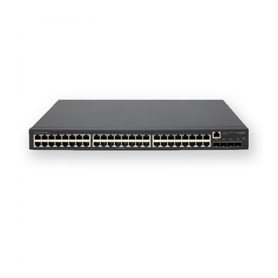
Preparing for installation This document provides an installation guide for the SE-S5130 switch series. Table1-1 describes the switch models included in the switch series. Table1-1 Switch series and models Switch series Model Product code (PID) SE-S5130-10S LS-SE-S5130-10S SE-S5130 switch series SE-S5130-18S LS-SE-S5130-18S Safety recommendations... - Page 8 Item Requirements CAUTION: Water or moisture might damage the circuits of the device. • Do not place the device near water or in a damp environment. • Install the switch in a clean, dry, and ventilated place where temperature is controlled in a stable range. •...
-
Page 9: Cleanliness
Item Requirements • Route different types of cables separately. • Keep power cords a minimum of 5 cm (1.97 in) away from other cables. • Ground the switch correctly. • To avoid ESD damage to the device or components, always wear an ESD wrist strap when you install or remove the device or ESD prevention components. -
Page 10: Examining The Installation Site
Table1-4 Corrosive gas concentration limits Average concentration (mg/m Maximum concentration (mg/m 0.01 0.03 0.05 CAUTION: As a best practice, control the corrosive gas concentrations in the equipment room at their average values. Make sure the corrosive gas concentrations do not exceed 30 minutes per day at their maximum values. -
Page 11: Checking Power Distribution Or Power Supply Environment
Category Definition Example environment controlled. direct ventilation cabinets far from • pollution sources, houses without Incompletely enclosed or shielded direct exposure to sunlight or rain, places. railway station platforms, and • Places far from pollution sources. stadiums. Simple equipment rooms, ordinary •... -
Page 12: Laser Safety
Item Requirements • Do not use the power cord provided with the switch on other devices. Laser safety WARNING! Disconnected optical fibers or transceiver modules might emit invisible laser light. Do not stare into beams or view directly with optical instruments when the switch is operating. The switch is a Class 1 laser device. - Page 13 Applicable device Product code Description Quantity models Grounding cable 1 (provided) All switch models Grounding screw 1 (provided) All switch models AC power cord 1 (provided) All switch models The appearance and parameters for AC power cords vary by countries and regions.
-
Page 14: Installing The Switch
CAUTION: Keep the tamper-proof seal on a mounting screw on the chassis cover intact, and if you want to open the chassis, contact H3C for permission. Otherwise, H3C shall not be liable for any consequence. Figure2-1 Hardware installation flow Start... -
Page 15: Installing The Switch In A 19-Inch Rack
Installing the switch in a 19-inch rack Installation methods Table2-2 Installation methods Switch models Mounting bracket type Installation procedure Mounting bracket A (provided), as shown by SE-S5130-18S callout (A) in Figure2-2 "Rack-mounting the switch by using front mounting brackets." Mounting bracket B (provided), as shown by SE-S5130-10S callout (B) in Figure2-2... -
Page 16: Rack-Mounting The Switch By Using Front Mounting Brackets
Rack-mounting the switch by using front mounting brackets Attaching the front mounting brackets to the switch Place the narrow flange of the front mounting bracket against the chassis side panel. Align the mounting bracket installation holes with the screw holes in the chassis. Fasten the M4 screws to secure the mounting bracket to the switch. -
Page 17: Mounting The Switch On A Workbench
If a standard 19-inch rack is not available, you can place your switch with upside up on a workbench. Grounding the switch WARNING! Correctly connecting the switch grounding cable is crucial to lightning protection, ESD, and EMI protection. For information about lightning protection, see H3C Network Devices Lightning Protection Guide. 2-11... -
Page 18: Grounding The Switch With A Grounding Strip
To protect against the following types of problems, use a grounding cable to connect the device to the earthing facility at the installation site: • Bodily injury from electric shocks. • Device and power and data line damages. • Electrical fires, lightning strokes, electromagnetic coupling interferences, ESD damages. You can ground the switch in one of the following ways, depending on the grounding conditions available at the installation site: •... -
Page 19: Grounding The Switch With A Grounding Conductor Buried In The Earth Ground
c. Use the needle-nose pliers to bend the bare wire. d. Hook the grounding cable to the post on the grounding strip, and use the hex nut to secure the cable to the post. Figure2-9 Connecting the grounding cable to a grounding strip (1) Grounding post (2) Grounding strip (3) Grounding cable... -
Page 20: Verifying The Connection After Grounding The Switch
10Ω. For locations with high soil resistivity, sprinkle some resistance reducer to reduce soil resistivity or replace soil around the grounding strip with soil with lower resistance. For information about resistance measurement, see H3C Network Devices Lightning Protection Guide. Connecting the power cord WARNING! •... -
Page 21: Verifying The Installation
• If a power line is routed from outdoors, verify that a surge protected power strip is used for the switch. NOTE: For information about lightning protection for the switch, see H3C Lightning Protection Guide. 2-15... -
Page 22: Accessing The Switch For The First Time
Accessing the switch for the first time When the switch is powered on for the first time, you can access and manage it from the Web interface or CLI interface. Managing the switch from the Web interface Using the default account and password for login The switch is set with factory-default Web login information. -
Page 23: Creating Web Login User Accounts
USB-to-RJ45 console USB connector RJ-45 connector cable The signal pinout for the RJ-45 connector of a serial console cable varies by vendor. To avoid abnormal configuration terminal display, use a serial console cable provided by H3C. For more 3-17... - Page 24 information, see Table1-8. To prepare a serial console cable yourself, make sure the signal pinout for the RJ-45 connector is the same as that shown in Table3-2. Connecting a DB9-to-RJ45 console cable CAUTION: Follow these guidelines when you connect a DB9-to-RJ45 console cable: •...
- Page 25 Click the following link, or copy it to the address bar on your browser and download the USB-to-RJ45 console driver. http://www.h3c.com/en/home/USB_to_RJ45_Console/ View the TXT file Read me in the Windows folder to check whether the Windows system of the configuration terminal supports the driver.
-
Page 26: Setting Terminal Parameters
Figure3-4 Finishing the driver installation Connect the standard USB connector of the cable to the USB port of the configuration terminal. Connect the RJ-45 connector of the cable to the console port of the switch. Setting terminal parameters To configure and manage the switch through the console port, you must run a terminal emulator program, such as TeraTermPro, on your configuration terminal. - Page 27 Power on the switch. During the startup process, you can access Boot ROM menus to perform tasks such as software upgrade and file management. The Boot ROM interface and menu options differ with software versions. For more information about Boot ROM menu options, see the software-matching release notes for the device.
-
Page 28: Maintenance And Troubleshooting
Verify that the operating temperature of the switch is in the acceptable range, and the power supply has good ventilation. Overtemperature can cause the power supply to stop working and enter protection mode. If the issue persists, contact H3C Support. Configuration terminal issues No display on the configuration terminal Symptom The configuration terminal does not have display when the switch is powered on. -
Page 29: Garbled Display On The Configuration Terminal
The configuration terminal displays garbled text. Solution To resolve the issue: Verify that the following settings are configured for the terminal: Baud rate—9600. Data bits—8. Parity—None. Stop bits—1. Flow control—None. If the issue persists, contact H3C Support. 4-23...
Need help?
Do you have a question about the SE-S5130 Series and is the answer not in the manual?
Questions and answers