Table of Contents
Advertisement
Advertisement
Table of Contents

Summary of Contents for impinj Speedway Revolution
- Page 1 UHF Gen 2 RFID Speedway Installation and Operations Guide Firmware Release: Octane 4.8.0, 25-Apr-11 ® Revolution Impinj, Speedway, Octane, and Powered by Impinj are either registered trademarks or trademarks of Impinj, Inc www.impinj.com Copyright © 2011, Impinj, Inc...
- Page 2 Consult the dealer or a qualified radio/TV technician for assistance. Changes to this product or modifications not expressly approved by the party Caution: responsible for compliance could void your authority to operate per FCC Part 15. Copyright © 2011, Impinj, Inc. Communication Code IPJ-REV-R220-USA1M1 IPJ-REV-R420-USA1M1...
- Page 3 RFID devices designed for use throughout the EEA must have a maximum radiated transmit power of 2W ERP in the frequency range of 865.6–867.6 MHz. For other EEA restrictions on RFID device use, please refer to the Impinj Declaration of Conformity (DoC) located at support.impinj.com.
-
Page 4: Table Of Contents
Installing and Connecting the Reader ... 8 Detailed Installation Procedures ... 9 Step 1: Position the Speedway Revolution Reader and Mount the Reader ... 9 Step 2: Connect the Antenna(s) to the Speedway Revolution Reader ... 10 Step 3: Power the Reader ... 10 Step 4: Connect Speedway Revolution to the Network ... - Page 5 Viewing the State of the Speedway Revolution Device ... 23 Chapter 4: Upgrading the Speedway Revolution Firmware ... 24 A Brief Overview of the Speedway Revolution Firmware ... 24 Upgrading the Firmware ... 24 Upgrading the Firmware with a USB Drive ... 25 Preparing the USB Drive for upgrade ...
-
Page 6: Chapter 1: Introduction
Intended Audience The intended audience for this guide is anyone installing a Speedway Revolution or xPortal reader. The assumed primary users of this guide are systems engineers and IT personnel with experience and basic knowledge of: •... -
Page 7: Impinj Support Information
Speedway Revolution Installation and Operations Guide Octane 4.8 Chapter 1: Introduction Impinj Support Information Visit the Impinj Support Web site at support.impinj.com for information about technical assistance. For guidelines on capturing data for analysis by Impinj technical support personnel, seeon page 31. Copyright © 2011, Impinj, Inc. -
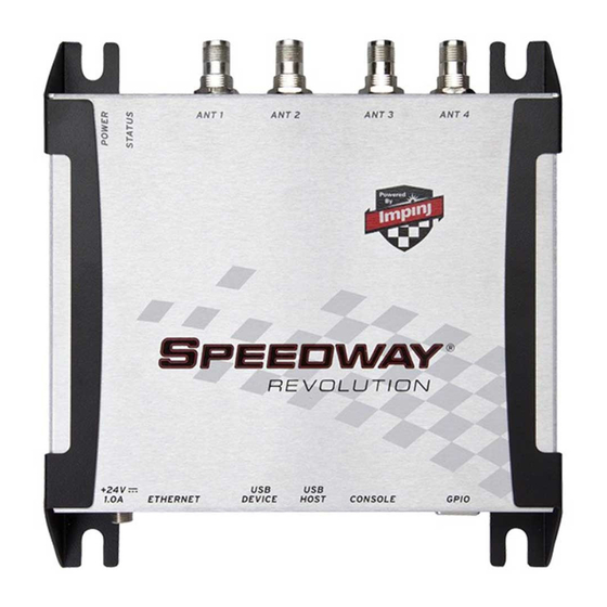
Page 8: Introduction To Speedway Revolution
Figure 1.0 Speedway Revolution Reader Low Power Usage • With a low power design, Speedway Revolution is capable of using Power over Ethernet (PoE). Using PoE simplifies deployment and dramatically reduces costs and greenhouse gas emissions of your RFID infrastructure. Using PoE does not compromise Speedway Revolution performance. -
Page 9: Speedway Xportal - Integrated Portal Reader
Chapter 1: Introduction Robust Reader Design • Just like its Speedway predecessor, Speedway Revolution uses a single circuit board design that delivers field-proven, enterprise-class quality and reliability. Speedway xPortal – Integrated Portal Reader Figure 1.2 Speedway xPortal-Reader Requirements for Using Speedway Revolution Environmental Requirement Operating temperature: -20º... -
Page 10: Power Requirements
See Appendix A: page 33 for details. If you are using a universal power supply module, you must use the Impinj approved part, number IPJ-A2001-000, which supplies +24V + 5%. Available AC power cords are: IPJ-A2051-USA (for North America) •... -
Page 11: Antenna Requirements
Speedway Revolution Installation and Operations Guide Octane 4.8 Chapter 1: Introduction Antenna Requirements Depending on the reader model you are installing, Speedway Revolution is equipped with two (R220) or four (R420) independent, bidirectional, and full duplex TX/RX monostatic antenna ports. -
Page 12: Chapter 2: Installing And Connecting Speedway Revolution
Chapter 2: Installing and Connecting Speedway Revolution This chapter provides details about the Speedway Revolution I/O ports and status LEDs, and explains how to install the reader and connect it to your network. Speedway Revolution Ports and LEDs The following graphic illustrates the I/O ports located on the Speedway Revolution Reader. -
Page 13: Installing And Connecting The Reader
LLRP activity Disconnected operation Installing and Connecting the Reader The primary installation and connection steps for Speedway Revolution are: 1. Position the reader appropriately for your environment. This may or may not involve mounting the reader. 2. Connect the antenna(s) to the appropriate ports on the reader. -
Page 14: Detailed Installation Procedures
Detailed Installation Procedures This section provides the details for each installation and connection step. Step 1: Position the Speedway Revolution Reader and (optionally) Mount the Reader Choose the appropriate location for the reader. Ideally you should always keep the unit away from direct sunlight, high humidity, extreme temperatures, and sources of electromagnetic interference. -
Page 15: Step 2: Connect The Antenna(S) To The Speedway Revolution Reader
Chapter 2: Installing and Connecting Step 2: Connect the Antenna(s) to the Speedway Revolution Reader Depending on the Speedway Revolution model you are installing, the reader has either two antenna ports (R220) or four antenna ports (R420). Each port is independent, bidirectional, and full duplex TX/RX (monostatic). -
Page 16: Step 4: Connect Speedway Revolution To The Network
PoE because the universal power supply is capable of higher power if both sources are connected. Step 4: Connect Speedway Revolution to the Network You are now ready to connect the installed Speedway Revolution to your network. You have two options: •... - Page 17 Version 0.60 or higher contains support for serial connections. 2. Using a Cisco style Console cable RJ-45 to DB9, Impinj part number IPJ-A4000-000, connect your PC’s valid/active COM port to the serial port on the reader as illustrated below: Figure 2.5 Speedway Revolution Serial Connection...
- Page 18 RShell to change the IP address on the reader from static to dynamic. See to Configure Network Settings Copyright © 2011, Impinj, Inc. Chapter 2: Installing and Connecting Using RShell to Configure Network Settings network as described on page 11. for Speedway Revolution on page 16 for details. connect Using RShell...
- Page 19 3. Select one of the available regions from the drop down list, see figure 2.8 Note : if you do not see your country or region listed, contact Impinj regarding current regulatory approval status. Click the REBOOT button. When changing the reader's operating region, the effect of the change does not take effect until the next reboot.
-
Page 20: Step 5: Test The Installed Reader
Step 6: Test the Installed Reader Confirm connections and functionality is correct by reading tags. Using the MultiReader, a Windows PC test application from Impinj, you can quickly verify reader operation by configuring various reader parameters and running simple inventory operations. For details... -
Page 21: Chapter 3: Configuring And Monitoring Speedway Revolution
You can often get up and running with little or no configuration using the default configuration settings in Speedway Revolution. If you are not using DHCP to assign IP addresses, you will need to configure a few of the reader’s network settings. -
Page 22: Rf Configuration
Programmer’s Guide. Using MultiReader to Configure and Test Speedway Revolution Impinj provides a simple, easy-to-use LLRP application for configuring and testing the basic RF behavior of Speedway Revolution. The MultiReader application is available from the Impinj support Web site at support.impinj.com. - Page 23 3. Connect to the reader by typing the reader’s IP address or hostname in the Name or IP Address field. You can determine the name and the IP address via the RShell show network summary command. Copyright © 2011, Impinj, Inc.
- Page 24 4. In Model, select the appropriate Speedway Revolution model (either Speedway R220 or Speedway R420). If you want MultiReader to issue a warning if it detects a model other than what is configured, confirm Warn on the model mismatch checkbox is selected.
- Page 25 12. Test your reader installation. Place one or more tags in the read-zone of one or more of the attached antennas. Select START Inventory. Tag reads appear in the large gray area on the left: Figure 3.5 Multireader Tag Inventory Display Copyright © 2011, Impinj, Inc.
-
Page 26: Monitoring Speedway Revolution
13. Select STOP Inventory Run to stop the tag inventory process. Monitoring Speedway Revolution Use RShell to monitor the reader health and performance when Speedway Revolution is up and running. This section presents the primary RShell commands for viewing the network and RFID statistics, plus the reader logs. -
Page 27: Viewing Rfid Parameters And Statistics
The RShell Reference Manual provides details. Configuring and Viewing Speedway Revolution Logs Speedway Revolution uses the standard Syslog protocol to forward its logged events to a remote Syslog server. The reader stores the logged events in its file system, accumulating and retaining this information across reboots. -
Page 28: Viewing The State Of The Speedway Revolution Device
For details about these commands, see the RShell Reference Manual. Viewing the State of the Speedway Revolution Device To display information about the current state of the reader itself, use the RShell show system command. -
Page 29: Chapter 4: Upgrading The Speedway Revolution Firmware
Chapter 4: Upgrading the Speedway Revolution Firmware Speedway Revolution contains firmware known as Octane. The current version of Octane is 4.8. This chapter details manually upgrading a single reader. In addition to supporting upgrade procedures, Speedway Revolution also provides methods for reverting firmware to a previous valid image and restoring firmware to factory default settings. -
Page 30: Upgrading The Firmware With A Usb Drive
7. Reboot the reader by issuing the following command: > reboot Speedway Revolution reboot process displays messages in the RShell console as it goes through each stage of the process. The reboot completes then the reader login prompt displays on the console. The reader status light displays solid green. -
Page 31: Preparing The Usb Drive For Upgrade
Preparing the USB Drive for upgrade 1. Insert a USB drive into your computer. 2. Create an impinj directory in the root of the USB drive along with the subdirectories revolution, upgrade, and images. The names of the directory are case sensitive and must all be lower case. - Page 32 Speedway Revolution Installation and Operations Guide Octane 4.8 Chapter 4: Upgrading Firmware Figure 4.1 Speedway Revolution Management Web Page Figure 4.2 Close-up of Reader Upgrade and Reboot Section of Management Web Page Copyright © 2011, Impinj, Inc.
-
Page 33: To Fall Back To The Previous Image
2. Log in to the reader. The pre-upgrade image is now running. Note : If there is no valid previous image, the response to the config image fallback command is Status=‘8, Permission-Denied’. Copyright © 2011, Impinj, Inc. -
Page 34: Chapter 5: Troubleshooting
Chapter 5: Troubleshooting If you experience a problem with Speedway Revolution, this brief chapter presents a few suggestions to correct the issue. Returning to the Default Configuration If you are experiencing a problem with the reader and are having difficulty pinpointing the cause, it is useful to return the reader to a known state. - Page 35 LLRP Outbound Timeout Secs Default Value root impinj Manual No syslog servers Error Error Error Dynamic (DHCP) speedwayr-xx-xx-xx (where xx-xx-xx are the last three digits of the MAC address) None None 5084 Enabled Enabled None Copyright © 2011, Impinj, Inc.
-
Page 36: Submitting Diagnostic Data For Analysis By Impinj Technical Support
Submitting Diagnostic Data for Analysis by Impinj Technical Support If Speedway Revolution is exhibiting RF behavior differing from what you expect and you are unable to determine the cause, you may want to submit relevant data for analysis by Impinj Technical Support. Using the Impinj MultiReader application, you can easily capture data relating to the problem scenario. - Page 37 10. Select Save Debug Data... A browse window opens. 11. Enter a file name and save the file in the desired location. 12. Send the .rdd file containing binary data to Impinj Technical Support. Visit the Impinj support Web site, support.impinj.com., for submission details or talk with your Impinj representative.
-
Page 38: Appendix A: Information Specific To Regions Of Operation
FCC OET Bulletin 56: Questions and Answers about Biological Effects and Potential Hazards of Radiofrequency Electromagnetic Fields Installation Speedway Revolution is capable of up to +32.5 dBm conducted power on the housing RF connector and requires professional installation. Power Speedway Revolution may only be operated with Impinj-approved antennas and can radiate no more than 36 dBm EIRP per FCC Part 15.247 regulations. - Page 39 Impinj model number IPJ-A0400-USA, CSL CS-777-2 (Brickyard) with 7 foot integrated pigtail to RP-TNC male connector; 2 dBi composite gain Impinj model number IPJ-A0401-USA or IPJ-A0402-USA (both Guardwall) with 6 foot • integrated pigtail to RP-TNC male connector; 6 dBi composite gain Impinj model number IPJ-A0404-000, Matchbox antenna with 20cm integrated •...
-
Page 40: Operation In European Union
Power European regulations allow a maximum radiated power of 33 dBm ERP (Effective Radiated Power) for high power RFID systems. The maximum Speedway Revolution output power is determined by the following equation: Maximum power setting (in dBm) = 33 – Antenna Gain (in dBd) + Cable loss (in dB) For example, for an application with an antenna gain of 6 dBd and cable loss of 2 dB, the reader output power can be set no higher than 33-6+2 = 29 dBm. -
Page 41: Operation In Other Global Regions
Installation Because Speedway Revolution is capable of up to +32.5 dBm conducted power on the housing RF connector, professional installation is required. Operation in China, Israel, Indonesia, Malaysia, Singapore, and Vietnam Regulations in these countries allow a maximum radiated power of 33 dBm ERP (Effective Radiated Power) for high power RFID systems. -
Page 42: Approved Antennas
Approved Antennas Consult with your registered reseller or Impinj provider for guidance on antenna selection for your region • Laird Technologies model number S9028PCL/R (left- or right-hand CP), with integrated 8 foot pigtail to RP-TNC male connector; 6 dBi composite gain Impinj model number IPJ-A0301-USA (Mini-Guardrail) with SMA female connector;... - Page 43 920.75 MHz 921.25 MHz 921.75 MHz 922.25 MHz 922.75 MHz 923.25 MHz 923.75 MHz 924.25 MHz 924.75 MHz 925.25 MHz 925.75 MHz 902.750 903.250 903.750 904.250 904.750 905.250 905.750 906.250 906.750 907.250 915.250 915.750 916.250 916.750 Copyright © 2011, Impinj, Inc.
- Page 44 LLRP Channel Number Table A.5 Hong Kong operating frequency band is 920 to 925 MHz with 500 kHz channel LLRP Channel Number Copyright © 2011, Impinj, Inc. Appendix A: Region Specific Information FCC Channel Number Center Frequency (MHz) spacing. FCC Channel Number Center Frequency (MHz) 917.250...
- Page 45 Center Frequency (MHz) 923.75 MHz 924.25 MHz 924.75 MHz 923.25 MHz 923.75 MHz 924.25 MHz 924.75 MHz 916.25 MHz 919.25 MHz 919.75 MHz 920.25 MHz 920.75 MHz 921.25 MHz 921.75 MHz 922.25 MHz 922.75 MHz Copyright © 2011, Impinj, Inc.
- Page 46 Table A.10 Philippines operating frequency band is 918 to 920 MHz with 500 kHz channel LLRP Channel Number Table A.11 Singapore operating frequency band is 920 to 925 MHz with 500 kHz channel LLRP Channel Number Copyright © 2011, Impinj, Inc. Appendix A: Region Specific Information spacing. FCC Channel Number spacing.
- Page 47 923.75 MHz 924.25 MHz 924.75 MHz 925.25 MHz 925.75 MHz 926.25 MHz 926.75 MHz 927.25 MHz 927.75 MHz 920.25 MHz 920.75 MHz 921.25 MHz 921.75 MHz 922.25 MHz 922.75 MHz 923.25 MHz 923.75 MHz 924.25 MHz Copyright © 2011, Impinj, Inc.
- Page 48 LLRP Channel Number Table A.14 Uruguay operating frequency band is 916 to 928 MHz with 500 kHz channel LLRP Channel Number Copyright © 2011, Impinj, Inc. Appendix A: Region Specific Information FCC Channel Number Center Frequency (MHz) spacing. FCC Channel Number Center Frequency (MHz) 924.75 MHz...
- Page 49 A.15 Vietnam operating frequency band is 920 to 925MHz with 500 kHz channel spacing. LLRP Channel Number FCC Channel Number Center Frequency (MHz) 920.25 MHz 920.75 MHz 921.25 MHz 921.75 MHz 922.25 MHz 922.75 MHz 923.25 MHz 923.75 MHz 924.25 MHz 924.75 MHz Copyright © 2011, Impinj, Inc.
- Page 50 Frequency plan is compliant to the State Radio Regulatory Commission (SRRC) of China. LLRP Channel Number Table A.17 Korea operating frequency band is 917 to 920.8MHz with 200kHz channel LLRP Channel Number Copyright © 2011, Impinj, Inc. Appendix A: Region Specific Information spacing. Center Frequency (MHz) 920.625 MHz...
- Page 51 Center Frequency (MHz) 915.6 MHz 915.8 MHz 916.0 MHz 916.2 MHz 916.4 MHz 916.6 MHz 916.8 MHz 917.0 MHz 917.2 MHz 917.4 MHz 917.6 MHz 917.8 MHz 918.0 MHz 918.2 MHz 918.4 MHz 918.6 MHz 918.8 MHz Copyright © 2011, Impinj, Inc.
-
Page 52: Appendix B: Gpio Details
Appendix B: GPIO Appendix B: GPIO Details Speedway Revolution includes a multipurpose I/O port that contains an RS-232 serial port, four opto-isolated inputs, four opto-isolated outputs, and a +5V supply. You access these features through a DE15 connector mounted on the side of the reader. - Page 53 LOW level input voltage Input current Input voltage range Output high voltage Output low (V-) voltage +0.5 Supply voltage range (V+ - V-) I/O Function Unit Conditions 24V input No damage 10K pullup 100mA load Copyright © 2011, Impinj, Inc.
-
Page 54: Appendix C: Speedway Xportal Installation
1. Vesa mounts (http://www.vesa.org/) is a standard LCD screen / computer monitor mounting pattern. There are many off-the-shelf brackets, arms, and stands that use the hole pattern shown in the red square on the figure C.2. Copyright © 2011, Impinj, Inc. Appendix C: Speedway xPortal Installation... - Page 55 The yellow circles on the figure highlight two knock-outs that can be removed if you wish to run cables into the unit directly from the wall. This provides a very clean installation, with no cables visible from the front. Figure C.2 xPortal Mounting Hole Types and Locations Copyright © 2011, Impinj, Inc.
-
Page 56: Conduit Attachment
Speedway Revolution Installation and Operations Guide Octane 4.8 Appendix C: Speedway xPortal Installation Conduit Attachment The round openings in the top and bottom of xPortal are designed so you can run metallic conduit directly to the unit. This allows Ethernet or power cables to be protected by standard EMT (electrical metallic tubing). - Page 57 Speedway Revolution Installation and Operations Guide Octane 4.8 Appendix C: Speedway xPortal Installation Figure C.4 Threaded ½ inch conduit connector Figure C.5 ½ inch conduit with a snap in flange connector Copyright © 2011, Impinj, Inc.
- Page 58 Speedway Revolution Installation and Operations Guide Octane 4.8 Appendix C: Speedway xPortal Installation Figure C.6 Snap in ½ inch conduit connector Figure C.7 A squeeze connector for the larger ¾ inch conduit tubing size. The connector has a nut and threads sized for the ½...
- Page 59 Speedway Revolution Installation and Operations Guide Octane 4.8 Appendix C: Speedway xPortal Installation Figure C.8 ¾ inch conduit squeeze connector, with a threaded interface to ½ inch conduit hole. Copyright © 2011, Impinj, Inc.
- Page 60 Impinj and the authorized recipient hereof. Impinj reserves the right to change its products and services at any time without notice. Impinj assumes no responsibility for customer product design or for infringement of patents and/or the rights of third parties, which may result from assistance provided by Impinj.
Need help?
Do you have a question about the Speedway Revolution and is the answer not in the manual?
Questions and answers