Advertisement
Quick Links
Door preparation
156mm
16mm
Door Cutout
3. Cylinder Installation
• Insert the key and turn to locked position.
• Insert #10 x38mm cylinder screw & tighten.
NOTE: test, beak should not depress.
• Assemble the cylinder through the lock so the
cylinder protrudes equally from both sides.
NOTE: the cylinder cam must rotate as shown
below. (cam turns towards front of door)
• Turn key to unlocked position and remove
key.
IMPORTANT: If installing SD7 with a
multipoint accessory kit, be sure to follow
the cylinder installation procedure within
the multipoint kit instructions.
5. Snib Lever Selection
• Break the snib lever pair in two.
TIP : Put the pair on a flat surface and
push down on the middle.
Push down
• Select the correct snib lever according
to the diagram below
interior
plate A
snib
lever A
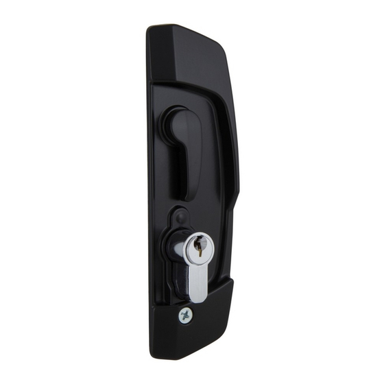
SD7 Sliding Security Door
Lock Installation Instructions
1. Lockbody preparation
• If the sticker has been broken or
removed,ensure that the rear slide
• The sticker on the rear of the lockbody
is to assist in easy installation. - Do not
remove.
• If the sticker
has been
broken or
removed,en-
sure that the
rear slide is
pushed
completely
down before
assembling the
lockbody into
the door
cutout.
cylinder
cylinder cam
6. Snib Lever & Plug Assembly
• Hold the snib lever vertically and insert
it into the snib lever hole in the interior
handle assembly.
• Turn the snib lever until horizontal to
secure it.
• Fit the snib plug in behind the snib
hole cover of the exterior handle
assembly.
interior
plate B
snib
lever
snib
lever B
Interior Handle
Assembly
(in this example)
lockbody
sticker
rear slide
beak
cylinder
screw
cam operation
snib
plug
Exterior Handle
Assembly
(in this example)
2. Lockbody installation
• Insert the lockbody into the door
cutout
• Secure the lockbody with two
#8x13mm lockbody screws
door cutout
4. Interior Furniture Preparation
• Select the interior handle assembly
to suit your door, then punch out
the snib hole
cover.
NOTE: Punch out from the
snib hole cover
7. Furniture Installation
• While holding the snib lever
horizontally place the interior and
exterior handle assemblies over the
lockbody.
• Ensure that the square drives on the
lever and snib lever are guided into
the lockbody.
• Secure the handle assembiles with
two #8x 32mm handle assembly
screws.
lockbody
lockbody screws
FRONT.
handle
assembly
screw
lever - square
drive
Advertisement

Summary of Contents for Allegion GAINSBOROUGH Austral Lock SD7
- Page 1 SD7 Sliding Security Door Lock Installation Instructions 2. Lockbody installation Door preparation 1. Lockbody preparation • Insert the lockbody into the door • If the sticker has been broken or cutout removed,ensure that the rear slide • Secure the lockbody with two •...
- Page 2 • If removal is delayed and scraping becomes necessary the • Rinse of with clean fresh water surface finish may suffer. Allegion (Australia) Pty Ltd Allegion (New Zealand) Pty Ltd Allegion (Australia) Pty Ltd Allegion (New Zealand) Limited Freephone: 1800 098 094...


Need help?
Do you have a question about the GAINSBOROUGH Austral Lock SD7 and is the answer not in the manual?
Questions and answers