Advertisement
Overview

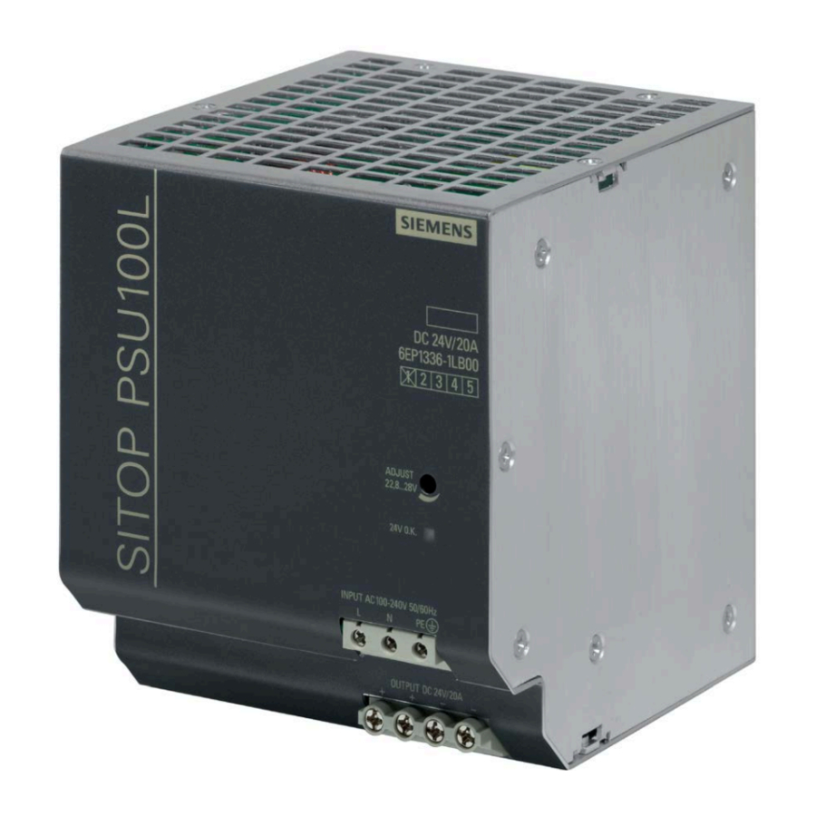
Figure 2: Design

Figure 3: Terminal data
*1) Do not subject the end atop to any higher stress
Description
The SITOP power supply is a built-in unit, degree of protection IP20, protection class I.
Primary switched-mode power supply for connection to 1-phase AC system (TN, TT system in accordance with IEC 60364-1) with rated voltages of 100 - 240 V, 50 - 60 Hz; 24 V DC output voltage, isolated, short-circuit and no-load proof.
See Figure 1 View of devices.
Safety instructions
NOTICE
Appropriate transport, proper storage, mounting, and installation, as well as careful operation and service, are essential for the error-free, safe and reliable operation of the device/system.
Setup and operation of this device/system are permitted only if the instructions and warnings of the associated technical documentation are carefully observed.
Only qualified personnel are allowed to install the device/system and commission it.
Mounting
Mounted on a standard mounting rail TH35-15/7.5 (EN 60715).
The device should be mounted so that the terminals are at the bottom.
A clearance of at least 50 mm must be maintained above and below the device (max. cable duct depth 50 mm).
See Figure 2 Design
Connecting up

Before starting any installation or maintenance work, the main system switch must be opened and measures taken to prevent it from being reclosed. If this instruction is not observed, touching live parts can result in death or serious injury.
It is only permissible to use an insulated screwdriver when actuating the potentiometer.
For installation of the devices, the relevant country specific regulations must be observed.

A miniature circuit breaker or motor circuit breaker must be provided on the input side.
The supply voltage must be connected according to IEC 60364.
Use copper wire certified for 60/75°C.
For operation at 2 line-to-line voltages, a suitable fuse protection is required at terminal N.
See Figure 3 Terminal data
*1) Do not subject the end stop to any higher stress
Structure
| 1 | AC input |
| 2 | DC output |
| 3 | Potentiometer |
| 4 | Indicator light (24 V O.K.) |
| 5 | DIN rail slider |
| 6 | Convection (natural convection) |
| 7 | Clearance above/below |
See Figure 2 Design
Operating mode
| Signaling |
| LED green: Output voltage OK |
Technical data
| Input variables |
| Rated input voltage U in rated : 1 AC 100 - 240 V, 50 - 60 Hz |
| Rated operating voltage: 1 AC 85 - 264 V, 88 - 375 V DC |
| Rated input current I in rated : 5.55/2.35 A |
| Coupled miniature circuit breaker to be connected in series Characteristic C: 10 A |
| Power consumption (active power) full load: 525 W |
| Output variables |
| Rated output voltage U out rated : 24 V |
| Setting range: 22.8 - 28.0 V, set via potentiometer on the device front |
| Rated output current I out rated : 20 A |
| Ambient conditions |
| Temperature in operation: -25... 70°C |
| Derating from 45 °C: 2.5% I out rated /K |
| Humidity (no condensation): 5 - 95 % |
| Overvoltage category: II to 2000 m |
| Pollution degree 2 |
| Option |
| Parallel connection of 2 devices to increase the performance is possible |
| Dimensions |
| Width × height × depth in mm: 110 × 125 × 125 |
Disposal guidelines
Packaging and packaging aids can and must always be recycled. The product itself may not be disposed of by means of domestic refuse.
Service and Support
You can obtain additional information from the home page (https://support.industry.siemens.com)

Documents / ResourcesDownload manual
Here you can download full pdf version of manual, it may contain additional safety instructions, warranty information, FCC rules, etc.
Download Siemens SITOP PSU100L - 6EP1336-1LB00 24 V/20 A Manual
Advertisement
Thank you! Your question has been received!


Need Assistance?
Do you have a question about the SITOP PSU100L that isn't answered in the manual? Leave your question here.