Bosch POPIT D9127U, D9127T - Module Installation Manual
- Installation manual (2 pages) ,
- Quick installation manual (2 pages)
- Also fits for
- D9127t
- Popit d9127u
- Popit d9127t
Advertisement
Overview
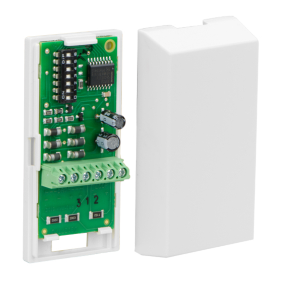
The D9127 Series POPIT Modules includes the D9127T (with magnetic tamper switch) and the D9127U (without tamper). They are used with a compatible control panel to expand beyond its standard number of on-board initiating points. Future system expansion is very economical as D9127 Series POPITs can be added anywhere along the two-wire data expansion loop. Both modules include proven technology that combines point supervision with individual device addressing on one pair of wires. Screw terminals provide reliable connections for the data expansion loop and supervised sensor loop wiring. The units are small and easily installed in standard outlet boxes, above false ceilings, closets, or other accessible locations.
Installation
Use the steps in this section to install and configure the POPIT module.
Remove the cover
- Insert a small flat-head screwdriver into one of the small slots in the side of the POPIT.
- Twist the screwdriver and remove the cover.
Remove the PCB
- Grasp the terminal block on the PCB in one hand.
- Three tabs hold the PCB. At the end with the two tabs, carefully but firmly, push one tab away from the PCB and lift the corner.
- Carefully but firmly, push the other tab away from the PCB and lift the entire PCB from the base.
Mount the POPIT base
Pull the wiring through the wiring opening (refer to Figure 1). Mount the POPIT base using the supplied hardware to prevent shorting the PCB.
Replace the PCB
- Grasp the terminal block on the PCB with one hand. Insert the DIP switch end of the PCB under the single tab.
- Carefully but firmly, pull the two tabs on the opposite ends away from the PCB.
- Gently lay the PCB in place and, if necessary, carefully, push the two tabs toward the PCB until the PCB is firmly in place.
Configuration of DIP switch
Refer to table below for DIP switch 0 settings and ZONEX and ZONEX 2 point address chart for DIP switch configuration settings for ZONEX and ZONEX 2.
| Control panel | DIP switch 0 setting |
| D7212B1 D8112 D9112B1 | Leave switch 0 ON. |
| D9412 | Refer to 9000 Series Operation and Installation Guide (P/N: 74-07692-000). |
| D9412G D7412G | Refer to ZONEX and ZONEX 2 point address chart |
| D7212G | Refer to ZONEX and ZONEX 2 point address chart |
| D7212GV2 | Refer to ZONEX and ZONEX 2 point address chart |
| D7212GV3 | Refer to ZONEX and ZONEX 2 point address chart |
| D7212GV4 D9412GV4 D7412GV4 | Refer to ZONEX and ZONEX 2 point address chart. |
| B9512G B9512G-E B8512G B8512G-E | Refer to ZONEX and ZONEX 2 point address chart |
| For additional D9127 installation information, refer to the compatible panel installation documentation. | |
Wiring Instructions
For more information on POPIT installation (including wire type, length, and run) and programming, refer to the D8125 POPEX Operation and Installation Guide (P/N: 74-04247-000) and control panel operation, installation, and programming manuals. Install a 33 kΩ end-of-line resistor at the farthest point on the loop for proper supervision. Replace the POPIT cover when the wiring is completed.

Figure 1: POPIT Wiring
 NOTICE!
When using 12 AWG (0.1 mm) maximum wire, use solid wire. If you use stranded wire, take care to insert all of the strands into the terminal block.
| Callout ― Description |
| 1 ― D8125 POPEX Module |
| 2 ― D9127U/T POPIT Module |
| 3 ― Tab |
| 4 ― DIP Switch |
| 5 ― Reed switch (D9127T only) |
| 6 ― Detector loop |
| 7 ― 33 kΩ EOL resistor |
| 8 ― Terminals (all): 12 AWG solid (maximum); 22 AWG (0.1 mm) stranded (minimum) |
| 9 ― Zone expansion loop to other POPITs |
| 10 ― Supervised |
| 11 ― Wire opening of POPIT base |
ZONEX and ZONEX 2 point address chart


1 ZONEX 1: Points 9 to 127 (D9412G); Points 9 to 75 (D7412G).
ZONEX 2: Points 129 to 247 (D9412G).
B299: x = B299 module address 0-5
* These point numbers are not available for B299 address 0.
Specifications
| Operating Voltage | Nominal 12 VDC supplied by control panel |
| Operating Current per D9127U/T | 0.8 mA Standby 0.8 mA Alarm |
Copyright
This document is the intellectual property of Bosch Security Systems, Inc. and is protected by copyright. All rights reserved.
Trademarks
All hardware and software product names used in this document are likely to be registered trademarks and must be treated accordingly.
Bosch Security Systems, Inc. product manufacturing dates
Use the serial number located on the product label and refer to the Bosch Security Systems, Inc. website at http://www.boschsecurity.com/datecodes/.

Bosch Security Systems, Inc.
130 Perinton Parkway
Fairport, NY 14450
USA
Bosch Sicherheitssysteme GmbH
Robert-Bosch-Ring 5
85630 Grasbrunn
Germany
© 2016 Bosch Security Systems, Inc.

Documents / Resources
References
![www.boschsecurity.us]() Home | Bosch Security and Safety Systems I North America
Home | Bosch Security and Safety Systems I North America![www.boschsecurity.com]() Datecodes | Bosch Security and Safety Systems I Global
Datecodes | Bosch Security and Safety Systems I Global
Download manual
Here you can download full pdf version of manual, it may contain additional safety instructions, warranty information, FCC rules, etc.
Download Bosch POPIT D9127U, D9127T - Module Installation Manual
Advertisement


Need help?
Do you have a question about the D9127U and is the answer not in the manual?
Questions and answers