Advertisement
Replacement Description
The ICM271 Fan Control Center is a solid state control designed and engineered for the replacement market. The ICM271 is designed specifically to replace the Carrier/BDP Gas Furnace Control Centers that have been used in new equipment for many years. The ICM271 is a form, fit and functional replacement of the OEM control requiring no modifications to the original wiring or to the appliance's sheet metal.
The ICM271 is a form, fit and functional replacement of the OEM control for the following Carrier/BDP part numbers:
| 302075-3 CES0110017 CES0110018 | HH84AA010 HH84AA011 HH84AA012 | HH84AA013 HH84AA020 P771-7002 |
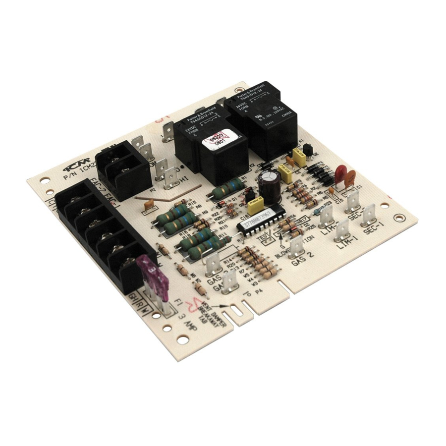
ICM271 Component Layout

Specifications
- Input Voltage
- Terminals: PR-1, PR-2, L1 and L2: 120 VAC
- Terminals: SEC-1 and SEC-2: 18-30 VAC
- Line Frequency: 60 Hz
- Operating Temperature: .-40ºF to +176ºF
- Maximum Operating Humidity: 95% R.H.
Non-condensing @ 50ºC - Time Delays
- Heat ON: 75 Seconds
- Heat OF: 105 Seconds
- Cool OFF: 90 Seconds
Pre-Installation Instructions
- Turn off gas supply and electrical power to equipment before servicing

- This device should be installed by a qualified technician with due regard for safety as improper installation could result in hazardous conditions.
- Failure to carefully read and follow these instructions before servicing or operating this control, could result in personal injury, death and/or property damage.
- Do not short out terminals on the gas valve or the ignition control module. A short or incorrect wiring will burn out the thermostat heat anticipator. It could also result in personal injury, death and/or property damage.
Operational Differences

The ICM271 has the same features and functions as the current Carrier/ BDP replacement (HH84AA020). The ICM271 has additional optional features and some slight operational differences than the older obsolete Carrier/BDP units. These options and operational differences are listed below.
 Note: Some older Carrier models did not have a cooling fan relay.
- On older Carrier/BDP models, the low-speed blower would still function if the 24 volt transformer malfunctions. This will not happen with the ICM271.
- If the JW1 jumper is cut, a constant low-speed blower will occur without any thermostat signal. Also, a signal applied to the GC or Y terminals will not bring on the hi-speed blower during the cooling mode. Therefore, the JW1 jumper must not be cut on cooling applications.
- The 24 volt circuit is fuse protected which is not true on earlier Carrier/BDP models. A 3 amp automotive type fuse is used to protect the thermostat and transformer circuits from shorts.
![warning]() Note: On the ICM271, a blown fuse will cause the lo-speed blower to come on and remain on until the fuse has been replaced.
Note: On the ICM271, a blown fuse will cause the lo-speed blower to come on and remain on until the fuse has been replaced. - The ICM271 has an easy-to-remove vent damper jumper plug. This jumper plug is factory assembled for use on applications not having a vent damper. If the application has a vent damper, remove the jumper plug and connect the vent damper wiring harness connector to the ICM271 circuit board.
The GAS1-to-GAS3 connection is made by a three-wire flame-proof switch, but in some standing-pilot applications this device is not present. In such applications, a jumper must be installed between GAS1 and GAS3 terminals.
A jumper should only be used on applications where a jumper exists on the previous furnace fan control board. This jumper should also include a male 1/4" spade connector to connect to your current gas valve's wiring harness.
Blower Speed Output
- Turn off gas supply and electrical power to equipment before servicing
Do not use this option on paired furnace applications.
The ICM271 has different blower speed options to match a specific application (see chart). The blower speed option used on the original furnace control may be very difficult to determine.
- If the old Carrier/BDP unit has (2) black relays just like the ICM271, then look for the JW1 jumper and R17 resistor on the Carrier/BDP board. They will be in the same location as the JW1 and R17 on the ICM271. If either one (JW1 or R17) has been cut, then cut the ICM271 equivalent. This will match the original Carrier/BDP blower speed option.
Blower Operating Modes
| Input From Thermostat | ICM271 As Shipped | G Blower Operation (Cut R17 Resistor) |
| W | Lo-Speed Heating Blower with 75 seconds ON Delay and 105 seconds OFF Delay | |
| G | Hi-speed cooling blower | Lo-speed heating blower |
| Y | No blower | Hi-speed cooling blower with 90 second OFF delay |
Installation Instructions
- Be sure all electrical power is turned off.
- Remove control box cover, exposing the old Carrier/BDP gas furnace control center.
- If furnace is equipped with a vent damper, disconnect the plug connector from the old board.
- Tag each wire as it is disconnected from the old furnace control center. Disconnect all of the wiring hookups.
- Remove the old Carrier/BDP furnace control center from the control box.
- Install the ICM271 fan control center into the control center box. Be sure the top edge of the ICM271 is in the mounting slot, just like the original board. Note: If the ICM271 is not installed correctly (i.e. behind the slot), an electrical short could occur.
- Reconnect all of the wires (removed in Step 4, above) to the proper terminals.
- If the appliance had a vent damper, break the vent damper jumper plug from the ICM271. Connect the original vent damper plug onto the ICM271.
- Restore electrical power to the furnace and put the furnace into operation. Allow the furnace to run through one complete heating or cooling cycle.
- If the furnace is functioning properly, replace all panels and leave this instruction sheet with the homeowner.
Troubleshooting

Troubleshooting to be performed by qualified technicians only. High voltage is dangerous – can cause injuries, death or property damage.
| Symptom | Remedy |
| Low speed fan runs continuously |
|
| No power to the thermostat (between R and terminals) |
|
| No fan output in cool mode |
|
| No fan output in heat mode |
|
| Fan cycles on and off |
|
Wiring Diagram

Legend:
| AUXLS | Auxiliary limit switch, manual reset (SPST- NC) (Down flow furnace models only) |
| BLWR | Blower motor relay (SPST-NO) |
| BVSS | Blocked vent shut-off switch, manual reset (SPST-NC) |
| CAP | Run capacitor |
| FL | Fusible link |
| HI/LO | Blower motor speed change relay (DPST) |
| ITLK | Blower door interlock switch (SPST-NO) |
| LS | Limit switch auto reset (SPST-NC) |
| MTR | Motor blower |
| TRANS | Transformer |
| VDP | Vent damper jumper plug |
 | Printed circuit board terminal |
| _______ | 24 VAC wiring |
| - - - - - | 115 VAC wiring |
 | Circuit on printed circuit board |
 | Screw terminal |
 | Equipment ground |
 | Not on all furnace models |
7313 William Barry Blvd., North Syracuse, NY 13212
(Toll Free) 800-365-5525
(Phone) 315-233-5266
(Fax) 315-233-5276

Documents / Resources
References
Download manual
Here you can download full pdf version of manual, it may contain additional safety instructions, warranty information, FCC rules, etc.
Advertisement


Need help?
Do you have a question about the ICM271 and is the answer not in the manual?
Questions and answers