Siemens OP121, OH121 - Smoke/Thermal Detector Installation Manual
- Installation instructions (2 pages) ,
- Installation instructions (4 pages)
Advertisement
These instructions are written in accordance with the installation guidelines of NFPA No. 72, National Fire Alarm Code, and CAN/ULC-S524, The Installation of Fire Alarm Systems.
DETECTOR PLACEMENT
For a clear air, 0 to 4000 ft/min velocity application, use 30 foot center spacing (900 sq ft) from NFPA Standard 72 initiating devices chapter and CAN/ULC-S524 as a starting point for a detector installation layout. This spacing, however, is based on ideal conditions – smooth ceiling, no air movement, and no physical obstructions. In some applications, considerably less area is protected adequately by each smoke detector. In all installations, place the detector on the ceiling, a minimum of 6 inches from a side wall, or on a wall, 6 inches from the ceiling.
Follow the drawings provided or approved by Siemens Industry, Inc. or by its authorized distributors. See NFPA 72, National Fire Alarm Code, initiating devices chapter for additional guidance on special issues such as beamed construction and high stockpiling.
TO AVOID NUISANCE ALARMS:
DO NOT locate the OP121/OH121 detector where excessive smoke concentrations exist under normal conditions, or in areas of prolonged high relative humidity where condensation occurs.
DO NOT locate the OP121/OH121 detector next to an oil burner, kitchen, or garage where exhaust fumes can trigger an alarm. Other causes of false alarms are dust accumulation, heavy concentrations of steam, heavy pipe or cigar smoke, and certain aerosol sprays.
AIR CURRENTS
Before a detector can sense a fire, the products of combustion or smoke must travel from the fire to the detector. Since their travel is especially influenced by air currents, consider the movement of air in the design of the system.
While combustion products tend to rise, drafts from hallways, air diffusers, fans, etc., may help or hinder the travel of combustion products to the detector. When positioning a detector at a particular location, give consideration to windows and doors, both open and closed, and to influencing air movement. Never install a detector in the air stream of a room air supply diffuser. It is better to position a detector closer to an air return.
SPECIFICATIONS
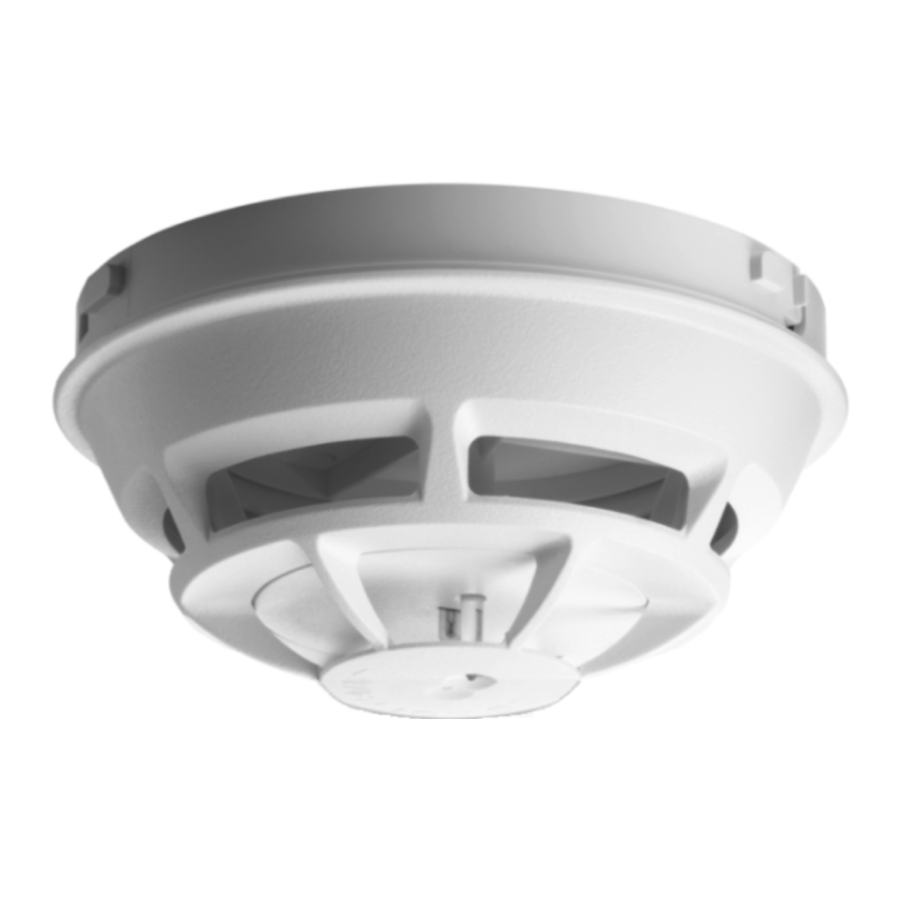
Figure 1 OP121 Photoelectric Smoke Detector

Figure 2 OH121 Photo Smoke Thermal Detector

Environmental
Operating Temperature (Model OP121): 320F (00C) to 1200F (490C)
Operating Temperature (Model OH121): 320F (00C) to 1000F (380C)
Humidity: Up to 95% RH, non condensing
Air Pressure: No effect
Air Velocity: 0 to 4000 ft/min. For open area protection and direct air duct application.
Thermal Alarm Temp. (Model OH121): 1350F (570C)
UL listed with STI Mechanical Protection Guard Model: STI-9604
(see www.STI-USA.com for details)
Electrical
| Voltage: | 16-27 VDC |
| Ripple: | 3V peak-to-peak |
| Supervisory Current: | 100μA max |
| Alarm Current: | 30-50mA |
| Start-up Time: | 30 seconds max |
DETECTOR WIRING
The OP121/OH121 should be connected as shown in Figure 3 using the separate mounting base, Model DB-11. Follow the control panel wiring connection drawing installed on the inside face of each control panel cover. See DB-11 instruction, P/N 315-094193, for base mounting. Duplicate wiring information is also in the Installation, Operation, and Maintenance Manual provided with every control panel. Note any limitations on the number of detectors and restrictions on the use of remote devices permitted for each circuit.

CONNECT DETECTOR ONLY TO CIRCUITS SPECIFIED IN DETECTOR AND PANEL LITERATURE OR SYSTEM MAY NOT OPERATE.

Figure 3 Installations and Wiring Diagram for OP121/OH121 Conventional Detectors

- Do not use looped wire under base terminal 5. Break wire run to provide supervision of connection.
- When a remote relay is used to control a critical system function, the relay and its associated detector and optional module(s) must be the ONLY devices on the initiating circuit.
INSTALLATION / REMOVAL OF DETECTOR
TO INSTALL:
- Rotate detector counterclockwise while gently pressing on it until the detector drops fully into base.
- Then rotate the detector clockwise until it stops and locks in place. Insert optional locking screw (Order Model LK-11).
TO REMOVE:
- · Loosen locking screw, if installed. Then rotate the detector counter clockwise until stop is reached.
- · Pull detector out of base.
LED INDICATOR OPERATION
The OP121/OH121 contains an LED indicator capable of flashing either one of three distinct colors: green, yellow, or red. The microprocessor based detector monitors the following:
- Smoke in its sensing chamber
- Smoke sensitivity is within the range indicated on the nameplate label (sensitivity verification)
- Internal sensors and electronics
Based on the results of these checks, the LED indicator flashes as follows:
| Flash Color | Condition | Flash Interval (Seconds) |
| Green | Normal supervisory operation. Smoke sensitivity is within rated limits. Double blinking first 3 min after power up or reset. Single blinking after the first 3 min. | 10 |
| Yellow | Detector is in trouble and needs replacement. | 5 |
| Red | Alarm | 2½ |
| No Flashes | Detector is not powered or replacement is needed. |
TESTING AND MAINTENANCE
To assure proper operation of the detector and control panel, it is required that both the Sensitivity test and the Functional test be conducted using the procedures outlined below.
SENSITIVITY TEST
The OP121/OH121 monitors its smoke sensitivity automatically and requires no test equipment. A green flash of the detector LED about every 10 seconds indicates that the smoke sensitivity is within its listed limits.
FUNCTIONAL TEST
To test the detector and control panel for functional operation, use SIEMENS Test Gas, P/N 500-649750. Follow the instructions on the gas canister label.
Smoke entry test mode: To test the detector for smoke entry, place the detector into a test mode. The test mode condition is automatically started after the initial power up and after every reset for a period of 3 minutes. It is recommended that a control panel reset be performed after every smoke entry test is conducted to restart the 3 minute test period. The test mode is indicated when the green LED is double blinking every 10 seconds. A normal operational mode is indicated (after 3 minutes) when the green LED is a single blink every 10 seconds. The test mode provides a reduced test time period and utilizes less concentration of test gas or aerosol.
Detector and control panel functionality can also be tested using the TM121 test magnet as shown in Figure 4 for the OP121 detector and Figure 6 for the OH121 detector. Place the magnet in the specific area at the bottom of the detector that is shown in Figure 5 for the OP121 detector and Figure 7 for the OH121 detector for at least 5 seconds with the colored side towards the centered LED. The detector will send an alarm to the panel.

Testing with the magnet only tests the circuit; it does not test the detector's sensing ability.
The TM 121 test magnet is a strong magnet that can be harmful to pacemaker wearers and to those with medical implants. Keep the magnet away from magnetic media such as credit cards and memory disks/chips.
UNDER NO CIRCUMSTANCES IS THE DETECTOR HEAD TO BE DISASSEMBLED. NO REPAIRS OR CLEANING SHOULD BE ATTEMPTED.
DO NOT PAINT
The detector/base plastic is marked DO NOT PAINT. This is intended to prohibit painting during routine maintenance of the occupancy which can affect proper operation of the detector.
COMPATIBLE CONTROL EQUIPMENT
| Equipment Compatibility Identifier | Installation/Wiring Instructions |
| SXL-EX SZM (FS-250C) | P/N 315-095997-8 P/N 315-034850C-4 |
The detector model number is the compatibility identifier.

Documents / Resources
References
Download manual
Here you can download full pdf version of manual, it may contain additional safety instructions, warranty information, FCC rules, etc.
Download Siemens OP121, OH121 - Smoke/Thermal Detector Installation Manual
Advertisement
Thank you! Your question has been received!


Need Assistance?
Do you have a question about the OP121 that isn't answered in the manual? Leave your question here.