Table of Contents

Related Manuals for Berthold DuoXpert LB 476 Level+


Summary of Contents for Berthold DuoXpert LB 476 Level+
- Page 1 DuoXpert LB 476 Level+ Operating Manual Embedded software version of EVU as of version 1.6.1 (CU and MU) Embedded software version of Current Output/HART and 7-Wire/RS485- Repeater as of version 1.0.0 56925-6BA2 Rev.00 03/2023...
- Page 3 BERTHOLD TECHNOLOGIES GmbH & Co. KG Calmbacher Str. 22 75323 Bad Wildbad, Germany www.berthold.com Telephone +49 7081 177-0 Fax +49 7081 177-100 industry@berthold.com...
- Page 5 LB 476 Level+ Table of Contents Table of Contents About this Operating Manual ................1 Applicable Documents ....................1 Some Prior Remarks ..................... 1 Storage Place ........................ 1 Target Group ........................ 1 Validity of the Operating Manual ................2 Structure of the Operating Manual ................2 Copyright ........................
- Page 6 Table of Contents LB 476 Level+ Main Menu Device Setup ................43 Menu Identification ....................44 7.1.1 Location ........................45 7.1.2 Device Information ..................... 46 7.1.3 Perform Software Update ..................47 Access .......................... 49 Menu Setup ......................... 51 7.3.1 System (Date / Time, Interfaces, Units, Network, Reset, Repair Det. Software) ..51 7.3.2 Sensors .........................
- Page 7 • Informations sur la sécurité, 56925BA59 (see appendix) Some Prior Remarks The product is handed over to you by the manufacturer BERTHOLD TECHNOLOGIES GmbH & Co. KG (designated as Berthold in the following) in a complete and func- tionally reliable condition. This operating manual illustrates how to: •...
- Page 8 LB 476 Level+ Validity of the Operating Manual The operating manual is valid from the delivery of the Berthold product to the user until its disposal. Version and release date of this operating manual can be found in the bottom of each page. Modification services are not performed by the man- ufacturer Berthold.
- Page 9 LB 476 Level+ 1 About this Operating Manual Warning Notes Warning notes are designed as follows: Signal Word Source and consequence Explanation, if required Prevention In case of emergency • Warning symbols: (warning triangle) draws attention to the hazard. •...
- Page 10 1 About this Operating Manual LB 476 Level+ 1.9.2 Symbols Used on the Device Read the operating manual Please observe the instructions in this operating manual. Electrostatic discharge Please note the handling instructions. Electrostatically endangered compo- nents. Please observe the instructions in this operating manual. Protective earth connection At this position, connect the protective earth conductor (PE).
- Page 11 Berthold, complies with relevant EU directives stated in the original declaration of conformity. This statement shall become void in the case of changes not authorised by Berthold or improper use. For the original declaration of conformity, please refer to Declaration of Conform- ity in the document “Technical Information”...
- Page 12 1 About this Operating Manual LB 476 Level+ 56925-6BA2 Rev.00, 03/2023...
- Page 13 EVU! • Observing the given safety instructions! • Carrying out the prescribed maintenance measures or having them carried out for you! • Only use accessories and spare parts from Berthold. 56925-6BA2 Rev.00, 03/2023...
- Page 14 • Operation without the safety precautions provided by the manufacturer. • Manipulation or avoidance of existing safety equipment. Berthold shall only accept liability for / guarantee the correspondence of the device to its publicised specifications. If the product is used in a way which is not described in the present operating manual, the device's protection is compromised and the warranty claim becomes invalid.
- Page 15 Authorised Persons Authorised persons are those who are either designated for the corresponding task due to legal regulations or those who have been authorised by Berthold for par- ticular tasks. When dealing with radioactive materials, a radiation safety officer must also be consulted.
- Page 16 2 Safety LB 476 Level+ 56925-6BA2 Rev.00, 03/2023...
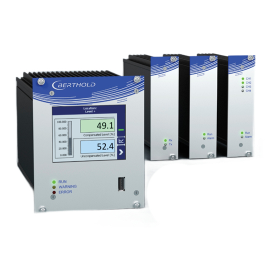
- Page 17 LB 476 Level+ 3 System Description System Description Overview The measuring device LB 476 Level+ is an industrial measuring system for the con- tactless and continuous determination of product level in a container whereby the measurement is optimized by a product buildup compensation (PBC). A complete measuring system consists of the following components: •...
- Page 18 3 System Description LB 476 Level+ 3.1.1 Measurement Arrangement LB 4700 Detectors Point source shield Slave module Mounting base Point detector LB 4700 Radiation beam Measurement line to LB 476 Product LB 476 Product buildups Current Output/HART module Rod detector TowerSENS LB 4700 5 analog outputs to DCS Measurement line to slave module Fig.
- Page 19 LB 476 Level+ 3 System Description 3.1.2 Measurement Arrangement LB 480 Detectors Point source shield Point detector LB 480 Measurement line 4 … 20mA to DCS (op- Mounting base tion) Radiation beam 7-Wire/RS485-Repeater module Product LB 476 Product buildups Current Output/HART module Rod detector TowerSENS LB 480 5 analog outputs to DCS RS485 measurement line...
- Page 20 3 System Description LB 476 Level+ Measuring Principle Gamma radiation is used to penetrate a medium in a container. The attenuation of the radiation is analysed to measure the level in the container. The evaluation unit DuoXpert LB 476 Level+ (master EVU) is used for the evaluation, transmission and visualisation of measured values which it receives from the connected detec- tors.
- Page 21 LB 476 Level+ 3 System Description System Components The master EVU and the slave module Fig. 3, item 1, item 2) are available with a wide range (100-240 V AC, 50/60 Hz) or with a 24 V supply (18-32 V DC). The 7- Wire/RS485-Repeater module and the Current Output/HART module are available in 100-240 V AC or 24 V DC versions.
- Page 22 3 System Description LB 476 Level+ 3.3.2 Master EVU 3.5'' touchscreen Mounting screws RUN LED Screws front plate WARNING LED Master/Slave 4-pin connector ERROR LED RJ45 socket for Ethernet USB port 32-pin plug connector Fig. 4 Front/rear view of the master EVU Operation Display / Touchscreen The EVU is operated via the touchscreen.
- Page 23 LB 476 Level+ 3 System Description Status displays of the master EVU The LEDs (Fig. 4, items 2-4) below the touchscreen show the current operating sta- tus of the master EVU. Display LED Description This LED lights up green if the device is in operation and fault-free.
- Page 24 3 System Description LB 476 Level+ 3.3.3 Slave Module The LEDs “Rx” and “Tx” are found on the front of the slave module. • The LED “Rx” flashes green when data is received. • The LED “Tx” flashes green when data is sent. •...
- Page 25 LB 476 Level+ 3 System Description 3.3.5 Current Output/HART Module The LEDs “Run”, “Error” as well as the status LEDs of the current outputs (OUT 1 to OUT 4) are found on the front of the Current Output/HART module. • The LED “Run” (Fig. 7, item 1) lights up green when the device is in opera- tion and fault-free.
- Page 26 3 System Description LB 476 Level+ Type Plate Application Master (M), Slave (S), 7-Wire/RS485- Repeater (B), 4x Current Out- Approval explosion protection (0 = no put/HART (A) explosion approval) Permissible temperature range for Power supply (1 = 24 V DC; 2=100…240 V operation (ambient temperature) AC -10 +10%) Power specifications...
- Page 27 The applicable national regulations of the country of use have to be observed! Repair and maintenance on the devices may only be performed by experts (see chapter 2.3). In case of doubt, the complete device must be returned to Berthold for repair.
- Page 28 4 Installation LB 476 Level+ Mounting of the Wall Housing Observe the permitted ambient conditions (refer to document "Technical Infor- mation" in the appendix). NOTICE It is recommended that the wall housing is to be protected from direct sun- light in order to maintain maximum ambient temperature (refer to “Technical Information”).
- Page 29 LB 476 Level+ 4 Installation Installation in the Wall Housing with Terminal Blocks The wall housing may be equipped differently, depending on requirements (refer to document “Technical Information”). Corresponding guide rails and terminal blocks are located in the wall housing for this purpose. NOTICE The master EVUs, slave modules, 7-Wire/RS485-Repeater modules and Cur- ...
- Page 30 4 Installation LB 476 Level+ Installation in the 19" Subrack with Terminal Blocks The 19" subrack can be equipped differently, depending on requirements (see cus- tomer-specific project documentation). The rear terminal blocks (Fig. 11, item 3) are used for the electrical connection. The subrack is installed in a 19" control cab- inet or a control panel (switchboard).
- Page 31 LB 476 Level+ 4 Installation Carefully slide the module into the subrack until the plug connector is in- serted into the terminal block. Tighten fixing screws (Fig. 11, item 6). Unused slots must be covered with dummy panels. The modules are correctly inserted and can be connected. ...
- Page 32 4 Installation LB 476 Level+ 56925-6BA2 Rev.00, 03/2023...
- Page 33 LB 476 Level+ 5 Electric Installation Electric Installation General Instructions j DANGER Danger to life from electric shock! The installation may only be carried out by a qualified electrician. Please adhere to the relevant safety regulations. Open the housing only in a dry environment and for installation, mainte- ...
- Page 34 When routing the cables, make sure that the cable insulation cannot be me- chanically damaged by sharp edges or movable metal parts. Use the approved Berthold cable or a cable with equivalent specifications for the connection. When routing the connection lines, make sure that signal lines (detector cables, power signal cables) are not laid together with ...
- Page 35 Cable bushings and blanking elements must comply with the applicable IP pro- tection class and with the requirements for the operational environment. We recommend ordering missing cable glands, blanking elements or adapters from Berthold. 56925-6BA2 Rev.00, 03/2023...
- Page 36 5 Electric Installation LB 476 Level+ 5.1.4 Protective Earth and Equipotential Bonding The protective earth conductor has to be connected to the terminals marked with "PE". The housing must be connected to local equipotential bonding. 5.1.5 EIA485 (RS485) Network For integration of EVU units into an EIA485 (RS485) network, all participants must be connected one after the other in the configuration Master/Master.
- Page 37 LB 476 Level+ 5 Electric Installation Electric Connection in the Wall Housing with Terminal Blocks j DANGER Danger to life from electric shock! The installation may only be carried out by a qualified electrician. Please adhere to the relevant safety regulations. ...
- Page 38 5 Electric Installation LB 476 Level+ Run the cables through the cable glands (Fig. 12, item 6) through the open- ings of the wall housing and through the counternut cable glands (Fig. 12, item 7). Screw the cable glands (Fig. 12, item 6) with the counternut cable glands (Fig.
- Page 39 LB 476 Level+ 5 Electric Installation Electrical Connection in the 19″ Subrack with Terminal Blocks j DANGER Danger to life from electric shock! The installation may only be carried out by a qualified electrician. Please adhere to the relevant safety regulations. ...
- Page 40 5 Electric Installation LB 476 Level+ The connection between the master EVU and slave modules is made with a 4-pin master/slave plug (see chap. 5.3.1). Terminal screw (M2.5) RJ45 connector (network) Opening terminal connection PE connection 4-pin master/slave plug (only master EVU) ter- minals 41-44 Fig.
- Page 41 LB 476 Level+ 5 Electric Installation 5.3.1 Master/Slave Plug The master/slave plug is only required when using LB 4700 detectors and slave mod- ules. Further information on the connection can be found in the appendix “Technical Information”. Fig. 14 Assignment Terminals master/slave plug 56925-6BA2 Rev.00, 03/2023...
- Page 42 5 Electric Installation LB 476 Level+ Switching Current Output Switching between "SOURCE" (active) and "SINK" (passive) is possible using the slide switch on the I/O board of the EVU. Ex works the EVU is in "SOURCE" mode. Please note that the polarity at the current output must be inverted as soon as the current output is switched at the switch.
- Page 43 LB 476 Level+ 6 Operation of the Software Operation of the Software System Start Fig. 16 Start screens with display of the software version IMPORTANT The communication between the detector and EVU is limited to 1200 baud. Ac- cordingly, there is a load time for data that are retrieved in the detector. All set values as well as the calibration data are stored in a non-volatile memory.
- Page 44 6 Operation of the Software LB 476 Level+ EVU Display IMPORTANT Changing the language of the user interface is changed in menu Device Setup | Setup | System | Interfaces | Languages. Description of the measuring location Button “Menu” Date and time Button “Diagram display”...
- Page 45 LB 476 Level+ 6 Operation of the Software Navigation Home (standard display) Diagram display Standard display One menu level back One menu level forward Fig. 18 Icons for navigation Status Messages No event Failure (error) Out of specification Information test (simulation) Function check Character D (detector) or M (measuring unit) Maintenance required...
- Page 46 6 Operation of the Software LB 476 Level+ Event Reports Events are displayed in the standard display and in the submenus and windows as a symbol. All events are displayed on the main screen. A specific “D” (only with connected LB 4700 detectors) indicates that a detector has an event, the prefix “M” (for measuring unit) indicates that there is an event in the LB 476 Level+ evaluation unit.
- Page 47 LB 476 Level+ 6 Operation of the Software IMPORTANT If you click the button <Close>, the event message is closed, the icon continues to be displayed. Input Field The input field appears by clicking on the blue display panels. When using the re- mote control software (see chapter 7.3.1 “Remote Control Software”), the keyboard of the PC can be used.
- Page 48 6 Operation of the Software LB 476 Level+ 56925-6BA2 Rev.00, 03/2023...
- Page 49 LB 476 Level+ 7 Main Menu Device Setup Main Menu Device Setup Main Menu - Device Setup Identification Chap. 7.1 Location Device Information Access Chap. 7.2 Setup Chap. 7.3 System Sensors Calibration Measurement Signal-Condition Detector Calibration Settings Date / Time Damping Configuration Detector #...
- Page 50 7 Main Menu Device Setup LB 476 Level+ Fig. 22 Menu “Main Menu”, "Device Setup" Menu Identification Device Setup | Identification You can make the following settings and read information in the Identification menu: • Display and change of the location name •...
- Page 51 LB 476 Level+ 7 Main Menu Device Setup 7.1.1 Location Device Setup | Identification | Location The location of the evaluation unit is displayed (Fig. 24, item 1) in the “Location” menu. The name can only be edited (7.2 Menu Access) in the access level "Stand- ard".
- Page 52 CU update (Control Unit) Device Information MU update (Measurement Unit) Selection window update file Software versions Process window Manufacturer Result window Fig. 25 Device Information The current software versions can be downloaded from the Berthold website (www.berthold.com). 56925-6BA2 Rev.00, 03/2023...
- Page 53 The secured settings should then be imported after the successful software update. The current software versions can be downloaded from the Berthold website (www.berthold.com). Perform CU Update Save the current update file of the CU software on a USB storage device.
- Page 54 EVU. The device restarts and the new MU software has been installed. NOTICE Berthold recommends calibrating the current outputs whenever a module has been installed/replaced or if a software update has been carried out. 56925-6BA2 Rev.00, 03/2023...
- Page 55 User Level Admin This access level is only intended for the system man- agement by Berthold. Automatic logout Activating the selection box (Fig. 26, item 1) auto- matically resets the access level “Standard” to “Basic”...
- Page 56 7 Main Menu Device Setup LB 476 Level+ NOTICE Incorrect measurement and calibration parameters can be set through unauthor- ised inputs. These can possibly lead to production losses and damage in the system. Protect the measuring system from unauthorised entries with a password and ...
- Page 57 LB 476 Level+ 7 Main Menu Device Setup Menu Setup Device Setup | Setup Fig. 28 Menu "Setup" 7.3.1 System (Date / Time, Interfaces, Units, Network, Reset, Repair Det. Software) Device Setup | Setup | System Fig. 29 Submenu "System" 56925-6BA2 Rev.00, 03/2023...
- Page 58 7 Main Menu Device Setup LB 476 Level+ Set Date and Time Device Setup | Setup | System | Date / Time IMPORTANT The date and time must always be set correctly so that all records (log files) have the correct metadata. The correct date is also indispensable for the decay com- pensation.
- Page 59 LB 476 Level+ 7 Main Menu Device Setup Interfaces Device setup | Setup | System | interfaces You can adjust the following settings in the submenu “Interfaces” (Fig. 31): • Local Display o Brightness / Touch o Input / Output •...
- Page 60 7 Main Menu Device Setup LB 476 Level+ Brightness / Timeout Device Setup | Setup | System | interfaces | Local Display | Brightness / Timeout “Timeout” refers to the period of time during which the display is not operated. The value “Timeout”...
- Page 61 LB 476 Level+ 7 Main Menu Device Setup Input / Touch Device Setup | Setup | System | Interfaces | Local Display | Input / Touch | Calibrate Touchscreen The mouse pointer automatically becomes visible when a mouse is inserted into the USB port.
- Page 62 7 Main Menu Device Setup LB 476 Level+ Confirm the calibration by clicking on the white screen to go back to "In- put/Touch" Execute a restart of the EVU after prompting. The touchscreen is calibrated. Language Device Setup | Setup | System | interfaces | Language Selection arrow Information window Fig.
- Page 63 LB 476 Level+ 7 Main Menu Device Setup CE Remote Control Device Setup | Setup | System | interfaces | Local Display | Remote Control By activating (Fig. 37, item 1) the CE Remote Control, the unit can be operated via the network connection.
- Page 64 7 Main Menu Device Setup LB 476 Level+ Units Device Setup | Setup | System | Units Clicking on the selection arrows lists the available units for the temperature value and the process value format. The selected unit is shown in the standard display and used in the calibration settings.
- Page 65 LB 476 Level+ 7 Main Menu Device Setup Network Device Setup | Setup | System | Network In the Network settings window, you can make changes to the network settings. The information can only be edited in the access level "Standard" (see page 49). Check box "DHCP Enabled"...
- Page 66 7 Main Menu Device Setup LB 476 Level+ Remote Control Software If the EVU is connected to a network at the RJ45 socket (Fig. 4, item 9), the EVU can be operated via a computer. The software can be loaded onto a USB storage device (see chapter “CE Remote Control”).
- Page 67 LB 476 Level+ 7 Main Menu Device Setup Reset Device (Evaluation Unit) Device Setup | Setup | System | Reset Device The evaluation unit can be restarted and reset to factory settings in the window “Reset Device”. Button Reboot Button Factory settings Window “Warning: Reboot”...
- Page 68 Corresponding information is displayed to the user in this menu. The current software versions for the detectors can be downloaded from the Berthold website (www.berthold.com). 56925-6BA2 Rev.00, 03/2023...
- Page 69 LB 476 Level+ 7 Main Menu Device Setup 7.3.2 Sensors Device Setup | Setup | Sensors You can perform the following settings and read information in the submenu “Sensors”: • Detector configuration (Fig. 43, item 1) o Add / Remove detectors o Settings of the detectors •...
- Page 70 7 Main Menu Device Setup LB 476 Level+ Detector Configuration Device Setup | Setup | Sensors | Detector Configuration In the window “Detector Configuration” the detectors for the measuring system are added and configured. Only configured detectors are listed and shown in the menu (Fig.
- Page 71 LB 476 Level+ 7 Main Menu Device Setup Detector Settings The settings of a configured detector are edited by selecting and clicking on <Edit> (Fig. 44, item 4). IMPORTANT The role of the selected detector must correspond the measurement task of the detector (Fig.
- Page 72 7 Main Menu Device Setup LB 476 Level+ Detector Settings Device Setup | Setup | Sensors | [NAME DETECTOR] You can adjust the following settings and read information in the submenu of the respective detector: • Overview of count rate, HV value and temperature •...
- Page 73 LB 476 Level+ 7 Main Menu Device Setup Detector Settings: Overview Device Setup | Setup | Sensors | [NAME DETECTOR] | Overview Important parameters and measured values of the detector are clearly displayed in the window “Overview”. Status information of the detector Device ID Live rate [cps] HV mode...
- Page 74 The submenu “Plateau” (Fig. 48) leads to the plateau measuring and the display of plateau values. Please contact your responsible service or sales partner, or Berthold directly, so that they can get a qualified assessment to the measured plateau.
- Page 75 Plateau Settings Device Setup | Setup | Sensors | [NAME DETECTOR] | Plateau | Plateau Settings The values in the window “Plateau Settings” are pre-set by Berthold on delivery and can be used in most situations. Input field HV start value in volts...
- Page 76 7 Main Menu Device Setup LB 476 Level+ Perform Plateau Measurement Device Setup | Setup | Sensors | [NAME DETECTOR] | Plateau | Plateau Measurement IMPORTANT The environmental conditions and the dose rate must be constant during the plateau recording. Observe the operating manual of the detector.
- Page 77 LB 476 Level+ 7 Main Menu Device Setup The recorded values are read and entered into the table (Fig. 51), the plateau curve (Fig. 52) is displayed and stored automatically. Plateau Table Device Setup | Setup | Sensors | [NAME DETECTOR] | Plateau | Plateau Table The data from each measurement point are listed in the plateau table.
- Page 78 7 Main Menu Device Setup LB 476 Level+ Plateau Curve Device Setup | Setup | Sensors | [NAME DETECTOR] | Plateau | Plateau Curve The mapped characteristic curve (Fig. 52, item 2) of the last complete plateau meas- urement is displayed in the window “Plateau Curve”. Date and Time of measurement recording Characteristic curve Fig.
- Page 79 LB 476 Level+ 7 Main Menu Device Setup Detector Settings: Temperature Device Setup | Setup | Sensors | [NAME DETECTOR] | Temperature The current temperature and the extreme values of the detector is displayed in the window “Temperature". Current temperature of the detector [°C] Maximum measured temperature [°C] Minimum measured temperature [°C] Fig.
- Page 80 7 Main Menu Device Setup LB 476 Level+ Detector Settings: High Voltage | Detector Type Device Setup | Setup | Sensors | [NAME DETECTOR] | High Voltage | Detector Type Internal device parameters are adjusted to suit the size of the used scintillator by setting the detector code.
- Page 81 LB 476 Level+ 7 Main Menu Device Setup NOTICE Default HV is preset by Berthold. A subsequent change is usually not necessary. The default value HV = 0 may only be set for testing purposes. An incorrect setting may cause malfunction.
- Page 82 7 Main Menu Device Setup LB 476 Level+ Detector Settings: Detector Service Device Setup | Setup | Sensors | [NAME DETECTOR] | Detector Service You can adjust the following settings and read information in the submenu “De- tector Service": • Device Information •...
- Page 83 NOTICE An update of the firmware of the detector may take 1 hour. Tipp The current software versions can be downloaded from the Berthold website (www.berthold.com). IMPORTANT In order for the system to detect the update file, it may not be located in an in- dex in the USB storage device.
- Page 84 7 Main Menu Device Setup LB 476 Level+ NOTICE Berthold recommends a test or a calibration of the current outputs, whenever if a software update has been carried out. Detector Settings: Service | Event Log Device Setup | Setup | Sensors | [NAME DETECTOR] | Detector Service | Event Log The last 25 events of the detector are displayed in the window "Event Log".
- Page 85 LB 476 Level+ 7 Main Menu Device Setup Detector Settings: Detector Service | Event Overview Device Setup | Setup | Sensors | [NAME DETECTOR] | Detector Service | Event Over- view All events that can be logged are chronologically presented in tabular form in the window “Event overview”.
- Page 86 7 Main Menu Device Setup LB 476 Level+ Detector Settings: Detector Service | Reset Detector Device Setup | Setup | Sensors | [NAME DETECTOR] | Detector Service | Reset Detec- In the window “Reset Detector”, the detector can be restarted and be reset to the factory settings.
- Page 87 Errors in calibration or in the parameter setting can lead to incorrect meas- urement results. This may possibly lead to a loss of production or to damage in the system. We encourage you to have the calibration and commissioning performed by Berthold service. Fig. 62 Menu “Calibration” 56925-6BA2 Rev.00, 03/2023...
- Page 88 7 Main Menu Device Setup LB 476 Level+ Calibration Settings Device Setup | Setup | Calibration | Calibration Settings The calibration settings are entered via the level detector submenus „Basic Setup“, “Compensated Level“ and “Uncompensated Level“. Fig. 63 Calibration Settings (exemplary with one LB 4700 detectors); submenu “Level Detector”...
- Page 89 LB 476 Level+ 7 Main Menu Device Setup General information for the compensated and uncompensated level calibration To monitor both, the "Compensated Level" and the "Uncompensated Level", the following settings and values must be set for every connected level detector in both submenus “Compensated Level”...
- Page 90 7 Main Menu Device Setup LB 476 Level+ Calibration Settings: Background Device Setup | Setup | Calibration | Calibration Settings | Detector | Compensated Level | Parameters | Background | Uncompensated Level | Parameters | Background The background count rate (Fig. 66, item 1) is the natural background radiation detected by the detector and must be measured at least for rod detectors.
- Page 91 LB 476 Level+ 7 Main Menu Device Setup Input field “Background” [cps] Input field “Read-In time” Button <Ok> Button <Start> Input field “Count Rate” [cps] Button <Cancel> Fig. 66 Calibration Parameters: Background Determine Background Click on the text field “Background” (Fig. 66, item 1). A new window “Measuring Background”...
- Page 92 7 Main Menu Device Setup LB 476 Level+ Calibration Settings: Nuclide Device Setup | Setup | Calibration | Calibration Settings | Detector | Compensated Level | Parameters | Nuclide | Uncompensated Level | Parameters | Nuclide The isotope used can be selected in the “Nuclide” tab. The half-life of the isotope is shown on the display field (Fig.
- Page 93 LB 476 Level+ 7 Main Menu Device Setup Calibration Settings: PV Range Device Setup | Setup | Calibration | Calibration Settings | Detector | Compensated Level | Parameters | PV Range | Uncompensated Level | Parameters | PV Range Display field “PV lower range value” [%] Display field “PV upper range value”...
- Page 94 7 Main Menu Device Setup LB 476 Level+ Calibration Settings: Table Device Setup | Setup | Calibration | Calibration Settings | Detector | Compensated Level | Table | Uncompensated Level | Table Column count rate [%] Number of calibration points (max.11) Column count rate [cps] Read-In-Time [s] Button...
- Page 95 LB 476 Level+ 7 Main Menu Device Setup Calibration Settings: Chart Device Setup | Setup | Calibration | Calibration Settings | Detector | Compensated Level | Chart | Uncompensated Level | Chart The characteristic curve of the calibration performed is shown in the tab “Chart”. Axis level [%} Axis count rate [cps] Characteristic chart...
- Page 96 7 Main Menu Device Setup LB 476 Level+ Calibrate Device Setup | Setup | Calibration All the data and selections entered and set in the "Calibration Settings" are trans- ferred to the measurement parameter set when the button “Calibrate” is clicked. Only after this action the settings can be used for measurement value calculation.
- Page 97 LB 476 Level+ 7 Main Menu Device Setup Recall Device Setup | Setup | Calibration | Recall In the "Recall" menu, the saved measurement parameters can be loaded into the calibration set. Button <Recall> Window “Recall measurement to parameter set” Fig.
- Page 98 7 Main Menu Device Setup LB 476 Level+ Device Setup | Setup | Calibration | PBC In the “PBC” menu, the product buildup compensation can be activated and the parameters of the PBC detector are set. Checkbox “PBC enabled” Display field “PBC live value” Input field “PBC threshold”...
- Page 99 NOTICE This functionality presupposes comprehensive knowledge and should only be ac- tivated and set up by a Berthold service technician or a specially trained and instructed person. You can make the following settings in the submenu GPC (gas properties compen- sation) (Fig.
- Page 100 7 Main Menu Device Setup LB 476 Level+ Fig. 76 Submenu „GPC“ GPC Calibration Device Setup | Setup | Calibration | GPC | GPC Calibration The "GPC calibration" is used to adapt the measuring sensitivity of the gas density detector to that of the level detector. The check box “GPC enabled” (Fig. 77, item 1) can only be selected when a detector is configured for gas density measurement.
- Page 101 LB 476 Level+ 7 Main Menu Device Setup GPC Calibration: Reference Rate The reference count rate measured at the GPC detector must be recorded at the same pressure at which the level calibration table was recorded. Therefore, it is recommended to read in the reference count rate immediately after recording the empty level count rate.
- Page 102 7 Main Menu Device Setup LB 476 Level+ GPC Calibration: Background The background count rate (Fig. 77, item 3) indicates the natural background radi- ation of the gas density detector if no radiation source is installed. This count rate is compensated by the system. Input field count rate [cps] Input field Read-In time [s] Button...
- Page 103 LB 476 Level+ 7 Main Menu Device Setup GPC Calibration: Factor M Calibration To calculate the correct factor M, click on the button “Factor M Calibration” (Fig. 77, item 5). In this table the first calibration point can be inserted directly from the available data with the button <Add Entry>.
- Page 104 7 Main Menu Device Setup LB 476 Level+ GPC Nuclide Settings Device Setup | Setup | Calibration | GPC | GPC Nuclide Settings Under "GPC Settings" the isotope of the source for gas density measurement can be selected (Fig. 81, item 1). The half-life time of the isotope is shown in the display field (Fig.
- Page 105 LB 476 Level+ 7 Main Menu Device Setup 7.3.4 Measurement Device Setup | Setup | Measurement The window “Measurement” is used for an overview of the measurement param- eters and calibration settings used. Fig. 83 Menu and submenus “Measurement” Basic Setup The measuring length of the detector (when using a rod detector) or of the source (when using a rod source) is displayed in the “Basic Setup”...
- Page 106 7 Main Menu Device Setup LB 476 Level+ 7.3.5 Signal Condition Device Setup | Setup | Signal Condition You can perform the following settings and read information in the “Signal Con- dition” submenu: • Damping (Time Constant) • XIP (X-Ray interference protection) •...
- Page 107 LB 476 Level+ 7 Main Menu Device Setup Signal Condition: XIP (X-Ray Inteference Protection) Device Setup | Setup | Signal Condition | XIP Radiation interference is X-ray or gamma radiation from any source other than the one intended for the measurement. Radiation interference can cause process value falsification.
- Page 108 7 Main Menu Device Setup LB 476 Level+ Detecting Interference Radiation XIP Pipe Welding seam tests with X-rays Radiation interference Distance up to 200 m Level Measurement Fig. 89 Interference radiation during weld inspection Detecting Interference Radiation The high gamma sensitivity of scintillation detectors may cause a false reading. To detect radiation interference, a double plausibility check can be enabled.
- Page 109 LB 476 Level+ 7 Main Menu Device Setup Further information on scenario A A relative level value is monitored, i.e. the alarm threshold is reached when ex- ceeding a maximum dose rate (multiple of calibration value at empty vessel or of low calibration point) at the detector.
- Page 110 7 Main Menu Device Setup LB 476 Level+ Interference Radiation Detection Flow Chart If radiation interference is detected, following will happen: − Measured value and current output are Interference "held". radiation detected − Error relay indicates alarm. The measurement is "held" up to the end of the defined hold time.
- Page 111 LB 476 Level+ 7 Main Menu Device Setup Signal Condition: Source Replacement Device Setup | Setup | Signal Condition | Source Replacement Notification for a source replacement can be activated in this window. The mainte- nance message “Replace source” is triggered when this date is reached. NOTICE For radiation protection reasons, a source replacement is recommended after 15 years.
- Page 112 7 Main Menu Device Setup LB 476 Level+ 7.3.6 Inputs Device Setup | Setup | Inputs The two digital inputs (DI) can be set, as well as displaying the DI status, in the submenu Inputs. Fig. 91 Menu "Inputs“; Submenu "Digital inputs (DI)“ Digital Inputs Assignment Device Setup | Setup | Inputs | Digital Inputs | DI Assignment The menu Assignment determines which function is executed when the digital in-...
- Page 113 LB 476 Level+ 7 Main Menu Device Setup Digital Inputs State Device Setup | Setup | Inputs | Digital Inputs | DI State The states of the two digital inputs are displayed in the window “DI State”. DI Input 1 state (ACTIVE / PASSIVE) DI Input 2 state (ACTIVE / PASSIVE)”...
- Page 114 7 Main Menu Device Setup LB 476 Level+ 7.3.7 Outputs Device Setup | Setup | Outputs You can make the following settings and read information in the submenu “Out- puts”: • Analog Output (AO) o AO Mapping o AO Monitoring o AO Failure Mode o AO Limits o AO Calibration...
- Page 115 LB 476 Level+ 7 Main Menu Device Setup Analog Output: AO Mapping Device Setup | Setup | Outputs | Analog Output (AO) | AO Mapping A function can be assigned to an analogue output in the window “AO Mapping”. The current output signal is between 4 mA and 20 mA. The corresponding percent value (e.g.
- Page 116 7 Main Menu Device Setup LB 476 Level+ Analog Output: AO Monitoring Device Setup | Setup | Outputs | Analog Output (AO) | AO Monitoring If “AO Monitoring” is activated (Fig. 97, item 1), the current output will be moni- tored.
- Page 117 LB 476 Level+ 7 Main Menu Device Setup Analog Output: AO Failure Mode Device Setup | Setup | Outputs | Analog Output (AO) | AO Failure Mode The alarm function is set when an error is detected at the current output in the window “AO Failure Mode”.
- Page 118 7 Main Menu Device Setup LB 476 Level+ Analogue Output: AO Limits Device Setup | Setup | Outputs | Analog Output (AO) | AO Limits By clicking on the input fields (Fig. 99, item 1, item 2), the values [mA] for the lower and upper current limit can be set.
- Page 119 For calibration of the current output, an ammeter (not included in the scope of delivery) is required, which is connected to the current output. Berthold recommends calibrating the current outputs whenever a module has been installed/replaced or if a software update has been carried out.
- Page 120 7 Main Menu Device Setup LB 476 Level+ Click on the button <Calibration> (Fig. 100, item 2). The device switches to test mode and a new window (Analog output calibra- tion) opens. The calibration point 4 mA is displayed and the current measuring instrument ...
- Page 121 LB 476 Level+ 7 Main Menu Device Setup Digital Outputs (DO) Device Setup | Setup | Output | Digital Outputs (DO) The signals of the digital outputs are switched via potential-free relay contacts. The contacts are controlled “fail safe”, i.e., in the event of an alarm, the current at the relay coil drops and the NO (normally open) contact is opened.
- Page 122 7 Main Menu Device Setup LB 476 Level+ Overflow Alarm The relay alarms if the switch point under Device Setup | Setup | Alarms | Overflow Alarm Settings is exceeded taking into ac- count the entered hysteresis. 56925-6BA2 Rev.00, 03/2023...
- Page 123 LB 476 Level+ 7 Main Menu Device Setup Additional Outputs Device Setup | Setup | Output | Additional Outputs The Current Output/HART module is addressed and controlled by the LB 476 system via RS485. 4 current outputs are available, whereby the first current output has HART (read only).
- Page 124 7 Main Menu Device Setup LB 476 Level+ Fig. 104 Submenu Additional Output “Analog Output 1” The submenus of the additional outputs are identical to the AO submenus Fig. 96 Analog Output Mapping (Assignment) and Fig. 100 Analog Output (Cal- ibration).
- Page 125 LB 476 Level+ 7 Main Menu Device Setup 7.3.8 Alarms Device Setup | Setup | Alarms You can make the following settings and read information in the submenu "Alarms": • Total Compensated Level Alarm Behaviour • Total Compensated Level Alarm Settings •...
- Page 126 7 Main Menu Device Setup LB 476 Level+ Total Compensated Level Alarm Behaviour Device Setup | Setup | Alarms | Total Compensated Level Alarm Behaviour The behavior in case of alarm (NE107 Status) for the process value can be set in the window “Total Compensated Level Alarm Behaviour”.
- Page 127 LB 476 Level+ 7 Main Menu Device Setup Total Compensated Level Alarm Settings Device Setup | Setup | Alarms | Total Compensated Level Alarm Settings You can set the values for the level alarms (max. and min.) and the hysteresis of these in the window “Total Compensated Level Alarm Alarm Settings”.
- Page 128 7 Main Menu Device Setup LB 476 Level+ Overflow Alarm Behaviour Device Setup | Setup | Alarms | Overflow Alarm Settings The behavior in case of alarm (NE107 Status) for the overflow alarm can be set in the window “Overflow Alarm Behaviour”. Selection arrow NE107 Status Selection “No Status”...
- Page 129 LB 476 Level+ 7 Main Menu Device Setup Overflow Alarm Settings Device Setup | Setup | Alarms | Overflow Alarm Settings When the count rate at the GPC detector falls below the switching point, an event message appears in the status display. If a digital output “Overflow Alarm” is as- signed under the function (Fig.
- Page 130 7 Main Menu Device Setup LB 476 Level+ Det.-Temp. Alarm Behavior Device Setup | Setup | Alarms | Det.-Temp. Alarm Behavior The behavior in case of alarm (NE107 status) can be set for the detector tempera- ture in the window “Det.-Temp. Alarm Behavior“. Selection arrow NE107 Status Selection “No Status”...
- Page 131 LB 476 Level+ 7 Main Menu Device Setup Detector Temperature Alarm Settings Device Setup | Setup | Alarms | Det.-Temp. Alarm Settings The values for the detector temperature (max. and min.) can be set in the window “Det.-Temp. Alarm Settings”. When there is exceeding or falling below the switching point, an event message appears in the status display.
- Page 132 7 Main Menu Device Setup LB 476 Level+ 7.3.9 Simulation Device Setup | Setup | Simulation A check for the output functions can be performed in the submenu “Simulation”. Fig. 112 Menu "Simulation" NOTICE When starting a simulation, the measurement is stopped and a status message appears.
- Page 133 LB 476 Level+ 7 Main Menu Device Setup Simulation Digital Outputs (DO) Device Setup | Setup | Simulation | Digital Outputs (DO) ERROR (DO-1) ALARM (DO-2) ALARM (DO-3) Button <Disable Test Mode> Dropdown field Fig. 114 Simulation Digital Outputs Click on the dropdown field (Fig. 114, item 5) and select "FAILURE" or “ALARM”...
- Page 134 7 Main Menu Device Setup LB 476 Level+ Menu Backup/Restore Device Setup | Backup/Restore You can make a backup copy of the configuration data, and perform a recovery in the submenu Backup/Restore. Fig. 115 Menu "Backup/Restore" 7.4.1 Backup Device Setup | Backup/Restore | Backup Button <Backup>...
- Page 135 LB 476 Level+ 7 Main Menu Device Setup The message ”No Errors” (Fig. 116, item 3) appears in the field “Backup data” for error-free backup files. Click the button <Edit> (Fig. 116, item 4), enter a description, and confirm with the Enter key.
- Page 136 7 Main Menu Device Setup LB 476 Level+ 7.4.2 Restore Device Setup | Backup/Restore | Restore Button < “previous” Number of recovery files on the USB storage device Button > ”next” Button <Restore> Recording date of the backup file Time of backup file recording Information about the backup data (error / error free) Confirmation window Fig.
- Page 137 LB 476 Level+ 8 Main Menu Diagnostics Main Menu Diagnostics Fig. 118 Menu "Diagnostics" Transmitter Temperature Diagnostics | Transmitter Temperature Temperature values from the evaluation unit (processor) are displayed in the menu item “Transmitter Temperature”. Minimal extreme value [°C] Maximum extreme value [°C] Current value [°C] Fig.
- Page 138 8 Main Menu Diagnostics LB 476 Level+ Events Diagnostics | Transm. Events Fig. 120 Menu "Transmitter Events" Information Events of the respective detector can be seen at Device Setup | Setup | Sensors | [NAME OF DETECTOR] | Detector Service. 8.2.1 Transmitter Event Log Diagnostics | Transmitter Events | Transmitter Event Log...
- Page 139 LB 476 Level+ 8 Main Menu Diagnostics Display Event Description Button <?> Button <Clear event log> Highlighted event Event no. Event title Event description Button <Close> Fig. 122 Display an event log information Click on a line in the list (Fig. 122, item 3). Click on <?>...
- Page 140 8 Main Menu Diagnostics LB 476 Level+ 8.2.2 Transm. Event Overview Diagnostics | Transm. Events | Transm. Event Overview All events that can be logged are chronologically presented in tabular form in the window “Event overview”. Activate the check box “Non-zero counter only” (Fig. 123, item 5) in order to display events that have occurred.
- Page 141 LB 476 Level+ 8 Main Menu Diagnostics Change Log Diagnostics | Change Log You can track changes that were performed on the device in the window “Change Log”. Date/Time of the change Short info of the change Old value New value Fig.
- Page 142 8 Main Menu Diagnostics LB 476 Level+ Data Log Diagnostics | Data Log You can set the log interval as well as delete and export the log data in the sub- menu “Data log”. IMPORTANT The data cannot be viewed on the EVU display and must be exported to a USB storage device to view it on a PC.
- Page 143 LB 476 Level+ 8 Main Menu Diagnostics Export Log Data Click on the button <Stop> (Fig. 125, item 2) to stop the data log process. Connect a USB storage device to the EVU (Fig. 3, item 5). Click on the button <Export>...
- Page 144 8 Main Menu Diagnostics LB 476 Level+ Network Data Log Diagnostics | Network Data Log In the window “Network data log”, the transmission of log data via the ethernet network can be started. With a log program, the data can be displayed on the PC. IMPORTANT The PC and the LB 47x have to be in the same IP subnet.
- Page 145 LB 476 Level+ 8 Main Menu Diagnostics Export Service Data Diagnostics | Export Service Data Button <Export service data> Process window Confirmation message Fig. 128 Export Service Data Connect a USB storage device to the EVU (Fig. 3, item 5). The USB storage device is recognized by the system after a few seconds and the button <Start Export>...
- Page 146 8 Main Menu Diagnostics LB 476 Level+ 56925-6BA2 Rev.00, 03/2023...
- Page 147 LB 476 Level+ 9 Troubleshooting Troubleshooting Error Search Problem Cause Measure Check power supply and Master unit: Screen black; LEDs fuses EVU does not work are not illuminated Slave module, 7-Wire/RS485- Check cabling, contact Repeater module, Current Out- module not clamped sockets put/HART module:...
- Page 148 9 Troubleshooting LB 476 Level+ Error Search (continued) Detector is not detected (soft- Check ID of the detector Incorrect ID in the configura- ware) (see type plate on the de- tion tector) Touchscreen does not respond Error in operating system Restart EVU ...
- Page 149 LB 476 Level+ 9 Troubleshooting Error Codes of the Evaluation Unit In the following tables you can find the EVU and detector error codes which give you exact information on how to fix them. The error codes of the detectors can be found in the operating instructions of the respective detectors.
- Page 150 Check, if mas- sive electromagnetic interferences have caused this event. Watchdog malfunction. Contact M105 WD Failure Berthold service, if this event occurs re- peatedly. M106 WD Off Watchdog is inactive. Malfunction of the real-time clock. Error in the internal real Check Date and Time.
- Page 151 LB 476 Level+ 9 Troubleshooting The date could not be verified at M116 Corrupt Date startup. Check date and time and set if necessary. 56925-6BA2 Rev.00, 03/2023...
- Page 152 Default parameter set default parameters. Calibrate device Decay compensation failed. Contact M302 Decay compensation Berthold service, if this event occurs re- peatedly. Detector temperature at / below lower M303 Det. Temp LL failure limit. Limit value can be configured. Fac- tory setting: -20°C.
- Page 153 Help Text Lost connection to at least one detector. Check detector settings and connections. M501 Detector not found Contact Berthold service, if this event oc- curs repeatedly. Temporarily lost connection to at least one detector. Check detector settings M502 Detector comm. error and connections.
- Page 154 Internal software failure of Current Out- put/HART module. Restart the device. M603 Add. out HW module Contact Berthold service, if this event oc- curs repeatedly. At least one current output loop of Cur- Add. out current loop M604 rent Output/HART module is open.
- Page 155 No action necessary. The device M703 Software update automatically returns to measuring mode after the software update is fin- ished. Internal software failure. Restart the de- M799 Internal program error vice. Contact Berthold service, if this event occurs repeatedly. 56925-6BA2 Rev.00, 03/2023...
- Page 156 Repair and servicing on the EVU and the modules may only be carried out by experts (see chapter 2.3 Qualification of the Personnel). In case of doubt, the complete EVU or modules should be sent to Berthold. NOTICE Repair on electronic circuits on the circuit boards of a field device may only be carried out in the manufacturer's factory.
- Page 157 LB 476 Level+ 10 Maintenance and Repair 10.1 Replacing of Fuses j DANGER Danger to life from electric shock! Replacing of fuses may only be carried out by a qualified electrician. Please adhere to the relevant safety regulations. Installation/maintenance may only be carried out if the device has been ...
- Page 158 10 Maintenance and Repair LB 476 Level+ Replacing Fuse in the Master Module Fixing screws Fuse 250V 1A T (5x20 mm) Screws Base Housing Fuse 250V TR5 T80mA (Ø 8,5 mm) Covering fuse Fig. 129 Replacing fuses master EVU De-energize the device. Loosen the four fixing screws (Fig.
- Page 159 LB 476 Level+ 10 Maintenance and Repair Replacing Fuse in the slave module, 7-Wire/RS485-Repeater module, Current Output/HART module Fixing screws Screws Housing Base Fuse Covering fuse Fig. 130 Exchange fuses slave module for example De-energize the device. Loosen the four fixing screws (Fig. 130, item 1) and remove the module from the wall housing or subrack.
- Page 160 10 Maintenance and Repair LB 476 Level+ 10.2 Cleaning The display is designed for maintenance-free operation. Make sure you keep the touchscreen and keyboard membrane clean. Use a cleaning cloth dampened with a cleaning agent to clean the equipment. Only use water with a little liquid soap or a screen cleaning foam.
- Page 161 LB 476 Level+ 10 Maintenance and Repair 10.3 Data Backup Activate the data log (see chapter 8.4) or the network data log (see chapter 8.5) so that all data are recorded. Perform a log data and service data backup at regular intervals.
- Page 162 11 Decommissioning LB 476 Level+ Decommissioning j DANGER Danger to life from electric shock! Decommissioning may only be carried out by qualified electricians. Please adhere to the relevant safety regulations. Decommissioning may only be carried out if the device has been de-ener- ...
- Page 163 LB 476 Level+ 11 Decommissioning The subrack can be folded down by the folding mechanism. Fold the subrack downward cautiously. Remove the network plug (Fig. 132, item 3). Remove all lines (Fig. 132, item 4). Loosen the cable gland (Fig. 132, item 5) on the bottom side of the wall housing and pull all cables from the wall housing.
- Page 164 11 Decommissioning LB 476 Level+ 11.2 Decommissioning 19" Subrack RJ45 connector (network) Clamp blocks PE cable Screw Connections Fig. 133 Decommissioning 19“ subrack De-energize the device. Remove the network plug (Fig. 133, item 1). Remove all lines from the clamp blocks (Fig. 133, item 2). Remove the PE cable (Fig.
- Page 165 LB 476 Level+ 11 Decommissioning 11.3 Disposal of Measurement System j CAUTION Toxic! The product contains electronic components containing toxic substances that are harmful to health. Disposal is to be carried out in accordance with the disposal regulations via a disposal expert.
- Page 166 12 Appendix LB 476 Level+ Appendix 12.1 Setup Protocol General data Date Number of detectors LB 4700 LB 480 Cascaded measurement Number of sources Source No. Activity Isotope Cs-137 Co-60 Vessel Product(s) Device configuration Installation variant Wall housing Subrack Connection Terminal block Power supply 100-240 V AC...
- Page 167 LB 476 Level+ 12 Appendix Parameters Password Language CE Remote control enabled Network DHCP active IP Address Subnet Gateway DNS-Server MAC Address Time constant level detector Time constant PBC detector enabled Cs-137 Co-60 Damping time constant Detection enabled Measurement Delay Hold Time I_O Factor RI Sigma...
- Page 168 12 Appendix LB 476 Level+ Parameters Digital Out- DO-2 Assignment: DO-3 Assignment: puts Total Comp. NE 107 Status when Alarm Level Alarm No Status Behaviour Out of Specification Failure Overflow NE 107 Status when Alarm Alarm Be- No Status haviour Out of Specification Failure Detector...
- Page 169 Modifications due to technical advancement reserved. © BERTHOLD TECHNOLOGIES GmbH & Co. KG Sprache: Deutsch Gedruckt in Deutschland 04/2023 Rev. No.: 06 BERTHOLD TECHNOLOGIES GmbH & Co. KG Calmbacher Str. 22 75323 Bad Wildbad Germany www.Berthold.com Mat No. 48452BA1...
- Page 171 DuoXpert LB 476 Level+ Technical Information Technische Information 56925TI1LP Rev.00 03/2023...
- Page 173 Technical Information LB 476 Level+ Technische Information Table of Contents Evaluation Unit and Extension Modules ............3 Connection Diagrams ..................4 2.1. Assignment Master EVU with LB 4700 Detectors ............4 2.2. Assignment Slave Module .................... 6 2.3. Assignment Master EVU with LB 480 Detectors ............8 2.4.
-
Page 174: Table Of Contents
Technical Information LB 476 Level+ Technische Information Inhaltsverzeichnis Auswerteeinheit und Erweiterungsmodule ............3 Anschlusspläne ....................4 2.1. Belegung Master AWE mit LB 4700 Detektoren ............4 2.2. Belegung Slave Module ....................6 2.3. Belegung Master AWE mit LB 480 Detektoren ............8 2.4. -
Page 175: Auswerteeinheit Und Erweiterungsmodule
Technical Information LB 476 Level+ Technische Information 1. Evaluation Unit and Extension Modules The modules can be installed either in wall housings or 19" subracks. It can be equipped differently, depending on requirements. The rear terminal blocks are used for the electrical connection. -
Page 176: Anschlusspläne
Technical Information LB 476 Level+ Technische Information 2. Connection Diagrams 2. Anschlusspläne 2.1. Assignment Master EVU with LB 4700 Detectors Belegung Master AWE mit LB 4700 Detektoren 2.1. TI-Abb. 1 Assignment master EVU with LB 4700 detectors Belegung Master AWE mit LB 4700 Detektoren 56925TI1LP Rev.00, 03/2023... - Page 177 Technical Information LB 476 Level+ Technische Information Terminal Block Master EVU with LB 4700 Detectors Klemmenblock Master AWE mit LB 4700 Detektoren Signal Signal DETECTOR LB 4700 GND C - 2 A - 2 DETECTOR LB 4700+ n.a. * C - 4 A - 4 n.a.
-
Page 178: Belegung Slave Module
Technical Information LB 476 Level+ Technische Information 2.2. Assignment Slave Module Belegung Slave Module 2.2. NOTICE HINWEIS Slave modules are only used with LB 4700 detectors. Slave Module werden nur bei Detektoren des Typs LB 4700 verwendet. TI-Abb. 2 Assignment slave module Belegung Slave Modul 56925TI1LP Rev.00, 03/2023... - Page 179 Technical Information LB 476 Level+ Technische Information Terminal Block Slave Module Klemmenblock Slave Modul Signal Signal DETECTOR SLAVE GND C - 2 A - 2 DETECTOR SLAVE +15 V n.a** n.a** C - 4 A - 4 n.a** n.a** C - 6 A - 6 n.a** n.a**...
-
Page 180: Belegung Master Awe Mit Lb 480 Detektoren
Technical Information LB 476 Level+ Technische Information 2.3. Assignment Master EVU with LB 480 Detectors Belegung Master AWE mit LB 480 Detektoren 2.3. TI-Abb. 3 Assignment EVU with LB 480 Detectors Belegung Master AWE mit LB 480 Detektoren 56925TI1LP Rev.00, 03/2023... - Page 181 Technical Information LB 476 Level+ Technische Information Terminal Block Master EVU with LB 480 Klemmenblock Master AWE mit LB 480 Signal Signal n.u. *** C - 2 A - 2 n.u. *** n.a. * C - 4 A - 4 n.a.
-
Page 182: Belegung 7-Leiter/Rs485-Repeater Modul
Technical Information LB 476 Level+ Technische Information 2.4. Assignment 7-Wire/RS485-Repeater Module Belegung 7-Leiter/RS485-Repeater Modul 2.4. NOTICE HINWEIS 7-Wire/RS485-Repeater modules are only used with LB 480 detectors. 7-Leiter/RS485-Repeater Module werden nur bei Detektoren des Typs LB 480 verwendet. TI-Abb. 4 Assignment 7-Wire/RS485-Repeater module Belegung 7-Leiter/RS485-Repeater Modul 56925TI1LP Rev.00, 03/2023... - Page 183 Technical Information LB 476 Level+ Technische Information Terminal Block 7-Wire/RS485-Repeater Klemmenblock 7-Leiter/RS485-Repeater Signal Signal n.a. * C - 2 A - 2 n.a. * n.a. * n.a. * C - 4 A - 4 n.a. * n.a. * C - 6 A - 6 n.a.
-
Page 184: Belegung Stromausgang/Hart Modul
Technical Information LB 476 Level+ Technische Information 2.5. Assignment Current Output/HART module Belegung Stromausgang/HART Modul 2.5. TI-Abb. 5 Assignment Current Output/HART module Belegung Stromausgang/HART Modul 56925TI1LP Rev.00, 03/2023... - Page 185 Technical Information LB 476 Level+ Technische Information Terminal Block Current Output/HART Klemmenblock Stromausgang/HART Signal Signal n.a. * C - 2 A - 2 n.a. * n.a. * C - 4 A - 4 n.a. * n.a. * C - 6 A - 6 n.a.
-
Page 186: Anschlusszeichnung Des Wandgehäuses
Technical Information LB 476 Level+ Technische Information 2.6. Assignment of the Wall-mounted Housing for arbitrary Ex- tension Modules Belegung des Wandgehäuses für beliebige Erweiterungsmo- 2.6. dule TI-Abb. 6 Assignment drawing of the wall-mounted housing Belegung des Wandgehäuses NOTICE HINWEIS The wall housing includes a sticker as shown in TI-Abb. 6. The terminal assignments of the three possible extension modules are also shown on the sticker. -
Page 187: Belegung Master/Slave Stecker
Technical Information LB 476 Level+ Technische Information 2.7. Assignment Terminals Master/Slave Plug Belegung Master/Slave Stecker 2.7. NOTICE HINWEIS The Master/Slave plug is only used in Master/Slave configurations with LB 4700 detectors. Der Master/Slave Stecker wird nur bei Master/Slave Anordnungen mit LB 4700 Detekto- ren verwendet. -
Page 188: Wandgehäuse
Technical Information LB 476 Level+ Technische Information 3. Wall Housing 3. Wandgehäuse TI-Abb. 8 Drawing wall housing Zeichnung Wandgehäuse Technical Data Technische Daten Max. assembly - 1 Master, 3 arbitrary extension modules with terminal blocks Max. Bestückung - 1 Master, 3 beliebige Erweiterungsmodule mit Klemmenblöcken Weight (with circuit board, 8.8 kg... -
Page 189: Baugruppenträger
Technical Information LB 476 Level+ Technische Information 4. 19” Subrack 4. 19“ Baugruppenträger TI-Abb. 9 Drawing 19“ subrack Zeichnung 19“ Baugruppenträger Technical Data Technische Daten Standard units 3HE/84TE Normeinheiten Max. Assembly 3 Master + 3 Slave / 2 Master + 6 Slave / 4 Master / 1 Master+ 9 Slave / 12 Slave Max. -
Page 190: Master Awe
Technical Information LB 476 Level+ Technische Information 5. Master EVU 5. Master AWE TI-Abb. 10 Drawing master EVU Zeichnung Master AWE Technical Data Technische Daten Weight 1200 g Gewicht Operational temperature -20 °C … +50 °C not condensing. Avoid direct sunlight. Un- obstructed air circulation must be provided to the subrack. - Page 191 Technical Information LB 476 Level+ Technische Information General ambient conditions Overvoltage category: II Pollution Degree: 2 Altitude: up to 2000 m Rel. humidity: 93% or less Allgemeine Umgebungsbedin- Überspannungskategorie: II gungen Verschmutzungsgrad: 2 Höhenlage: bis zu 2000 m Rel. Luftfeuchtigkeit: 93% oder weniger Degree of protection IP20 Schutzart...
- Page 192 Technical Information LB 476 Level+ Technische Information Interfaces Schnittstellen Current output 4…20 mA internally switched from power source to sink current (according to NAMUR recommendation NE 006 and NE 043). Dip switch source/sink on the electronic board of the LB 47x. Standard setting is source current. Continuous short circuit proof and galvanically isolated (500 V).
- Page 193 Technical Information LB 476 Level+ Technische Information RS485 For communication between Master EVU, 7-Wire/RS485- Repeater module, Current Output/HART module and test- ing and evaluation purposes. Not isolated from main electronics and USB port, electrically isolated from remain- ing I/Os (500 V). Zur Kommunikation zwischen Master AWE, 7-Leiter/RS485 RS485 Repeatermodul und Stromausgang/HART Modul, sowie zu...
-
Page 194: Slave Modul
Technical Information LB 476 Level+ Technische Information 6. Slave Module 6. Slave Modul TI-Abb. 11 Drawing slave module Zeichnung Slave Modul Technical Data Technische Daten Weight 600 g Gewicht Operational temperature -20 °C … +50 °C, not condensing. Avoid direct sunlight. Unobstructed air circulation must be provided to the sub- rack. - Page 195 Technical Information LB 476 Level+ Technische Information Overvoltage category: II General ambient conditions Pollution Degree: 2 Altitude: up to 2000 m Rel. humidity: 93% or less Allgemeine Umgebungsbedin- Überspannungskategorie: II gungen Verschmutzungsgrad: 2 Höhenlage: bis zu 2000 m Rel. Luftfeuchtigkeit: 93% oder weniger Degree of protection IP20 Schutzart...
-
Page 196: 7-Leiter/Rs485-Repeater Modul
Technical Information LB 476 Level+ Technische Information 7. 7-Wire/RS485-Repeater Module 7. 7-Leiter/RS485-Repeater Modul TI-Abb. 12 7-Wire/RS485-Repeater module 7-Leiter/RS485-Repeater Modul Technical Data Technische Daten Weight 500 g Gewicht Operational temperature -20 °C … +50 °C not condensing. Avoid direct sunlight. Unob- structed air circulation must be provided to the subrack. - Page 197 Technical Information LB 476 Level+ Technische Information Overvoltage category: II General ambient conditions Pollution Degree: 2 Altitude: up to 2000 m Rel. humidity: 93% or less Allgemeine Umgebungsbed- Überspannungskategorie: II ingungen Verschmutzungsgrad: 2 Höhenlage: bis zu 2000 m Rel. Luftfeuchtigkeit: 93% oder weniger Degree of protection IP20 Schutzart...
-
Page 198: Stromausgang/Hart Modul
Technical Information LB 476 Level+ Technische Information 8. Current Output/HART Module 8. Stromausgang/HART Modul TI-Abb. 13 Current Output/HART module Stromausgang/HART Modul Technical Data Technische Daten Weight 500 g Gewicht Operational temperature -20 °C … +50 °C not condensing. Avoid direct sunlight. Un- obstructed air circulation must be provided to the subrack. - Page 199 Technical Information LB 476 Level+ Technische Information Overvoltage category: II General ambient conditions Pollution Degree: 2 Altitude: up to 2000 m Rel. humidity: 93% or less Allgemeine Umgebungsbed- Überspannungskategorie: II ingungen Verschmutzungsgrad: 2 Höhenlage: bis zu 2000 m Rel. Luftfeuchtigkeit: 93% oder weniger Degree of protection IP20 Schutzart...
-
Page 200: Nummernschlüssel Lb 47X
Technical Information LB 476 Level+ Technische Information 9. Number Key LB 47x 9. Nummernschlüssel LB 47x TI-Abb. 14 Number key Nummernschlüssel Only available as Ex-i version Nur verfügbar als Ex-i Version Only available as a standard version Nur verfügbar als Standard-Version *Other Hardware *Andere Hardware 56925TI1LP Rev.00, 03/2023... - Page 201 Technical Information LB 476 Level+ Technische Information 10. EG-Declaration of Conformity LB 47x 56925TI1LP Rev.00, 03/2023...
-
Page 202: Eg-Konformitätserklärung Lb 47X
Technical Information LB 476 Level+ Technische Information 10. EG-Konformitätserklärung LB 47x 56925TI1LP Rev.00, 03/2023... -
Page 203: Eu-Konformitätserklärung 7-Leiter/Rs-485 Repeater
Technical Information LB 476 Level+ Technische Information 11. EU-Declaration of Conformity 7-wire/RS-485 re- peater 11. EU-Konformitätserklärung 7-Leiter/RS-485 Re- peater 56925TI1LP Rev.00, 03/2023... -
Page 204: Eu-Konformitätserklärung 4X Spannungsausgang/Hart
Technical Information LB 476 Level+ Technische Information 12. EU-Declaration of Conformity 4x Current Out- put/HART 12. EU-Konformitätserklärung 4x Spannungsaus- gang/HART 56925TI1LP Rev.00, 03/2023... -
Page 205: Konformitätserklärung 7-Leiter/Rs-485 Repeater
Technical Information LB 476 Level+ Technische Information 13. UK Declaration of Conformity 7-wire/RS-485 re- peater 13. UK Konformitätserklärung 7-Leiter/RS-485 Re- peater 56925TI1LP Rev.00, 03/2023... -
Page 206: Konformitätserklärung 4X Spannungsausgang/Hart
Technical Information LB 476 Level+ Technische Information 14. UK Declaration of Conformity 4x Current Out- put/HART 14. UK Konformitätserklärung 4x Spannungsaus- gang/HART 56925TI1LP Rev.00, 03/2023... -
Page 207: Nrtl Zertifikat Us/Can Wandgehäuse
Technical Information LB 476 Level+ Technische Information 15. NTRL Certification US/CAN wall-mounted hous- 15. NRTL Zertifikat US/CAN Wandgehäuse 56925TI1LP Rev.00, 03/2023... - Page 208 Technical Information LB 476 Level+ Technische Information 56925TI1LP Rev.00, 03/2023...
- Page 209 Technical Information LB 476 Level+ Technische Information 56925TI1LP Rev.00, 03/2023...
-
Page 210: Ntrl Zertifikat Us/Can Duoxpert Lb 47X
Technical Information LB 476 Level+ Technische Information 16. NTRL Certifikate US/CAN DuoXpert LB 47x 16. NTRL Zertifikat US/CAN DuoXpert LB 47x 56925TI1LP Rev.00, 03/2023... - Page 211 Technical Information LB 476 Level+ Technische Information 56925TI1LP Rev.00, 03/2023...
-
Page 212: Übersicht Zubehör
Technical Information LB 476 Level+ Technische Information 17. Parts Overview 17. Übersicht Zubehör Mat. No. Description Mat.-Nr. Beschreibung 64656 LB 476-02-M0 Level+ Transmitter (100…240 VAC) LB 476-02-M0 Füllstand + Auswerteeinheit (100…240 VAC) 64657 LB 476-01-M0 Level+ Transmitter (24 VDC) LB 476-01-M0 Füllstand + Auswerteeinheit (24 VDC) 73033 LB 47x-02-A0 4x Current Output/HART (100…240 VAC) LB 47x-02-A0 4x Stromausgang/HART (100…240 VAC) - Page 213 Technical Information LB 476 Level+ Technische Information 37526 Front Cover Plate 21 HP / 3 RU (Master) Blindplatte 21TE / 3 HE (Master) 59501 Front Cover Plate 7 HP / 3 RU (Slave) Blindplatte 7TE / 3 HE (Slave) Operating Manual LB 476 Level+, German 56925-6BA1 Betriebsanleitung LB 476 Füllstand +, Deutsch Operating Manual LB 476 Level+, English...