
Related Manuals for Darkly Labs EMBLASER 2


Summary of Contents for Darkly Labs EMBLASER 2
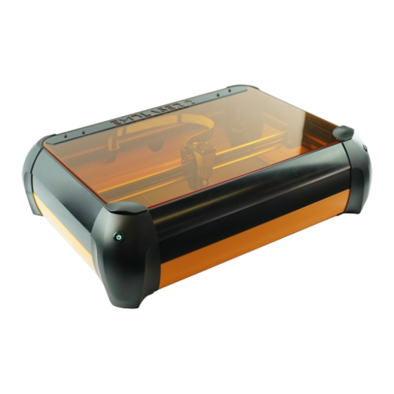
- Page 1 Darkly Labs EMBLASER 2 User Manual English Deutsch Emblaser 2 User Manual Rev 1.65...
- Page 3 IMPORTANT To keep your Emblaser 2 operating correctly, it is important to follow the MAINTAINENCE SCHEDULE in Chapter 6. Failing to do so could result in reduced performance or damage to your machine.
-
Page 4: Table Of Contents
FDA Label Identification ................... 9 Introduction What’s in the box ....................10 Unpacking your Emblaser 2 ................... 11 Getting to know your Emblaser 2 ................12 Workspace and Dimensions ................... 13 First Steps Your Creative Space ....................14 Plugging In ....................... 15 Installing the Software ................... - Page 5 Caring for your Emblaser 2 Maintenance Schedule .................... 22 General Maintenance ....................23 Basic Lens Cleaning ....................24 Unblocking the Air-Assist nozzle ................25 Replacing the Diode Module .................. 26 Updating the Controller Firmware ................. 28 Reference Emblaser 2 Specifications ..................29 Material Property Table ..................
-
Page 6: For Your Safety
1. FOR YOUR SAFETY To prevent damage to your Emblaser 2 or injury to yourself or to others, read the following safety precautions carefully. Keep these safety instructions where all those who use the product will read them. WARNINGS Do not use in the presence of flammable... -
Page 7: Notices
Only Darkly Labs brand accessories certified by Darkly Labs specifically for use with your Emblaser 2 are engineered and proven to operate within its operational and safety requirements. The use of non-Darkly Labs accessories could damage your Emblaser 2 and void your warranty. -
Page 8: Notices For Customers In The Usa
CAUTIONS Modifications The FCC requires the user be notified that any changes or modifications made to this device that are not expressly approved by Darkly Labs may void the user’s authority to operate the equipment. Interface Cables Use the interface cables sold or provided by Darkly Labs for your equipment. Using other interface cables may exceed the limits of Class B Part 15 of the FCC rules. -
Page 9: Fda Label Identification
Figure 1 shows examples of these labels and their location on the Emblaser 2. Laser Aperture Label LASER IEC 60825.1: 2014... -
Page 10: Introduction
Congratulations on receiving your new Emblaser 2 To help get you started, visit our online Help Centre for the user manual, software and more information: tinyurl.com/e2start Always use your Emblaser 2 safely and never leave it operating unattended. SAFETY CHECKLIST WARNING! -
Page 11: Unpacking Your Emblaser 2
Unpacking your Emblaser 2 2: Remove internal spacer 1: Peel off protective 3: Remove motor packaging. and accessory box. lid covering 4: Remove laser carriage clip. Keep all your packaging mateirals in case you need to return your Emblaser 2 for repair. -
Page 12: Getting To Know Your Emblaser 2
Getting to know your Emblaser 2 Air-Assist Accessory (optional) Laser Unit Assembly On/Off Power Button Front Side Rear Side Electronics Pod Exhaust Hose Connector Laser Heat-sink Laser Lens Aperture Lid Handles Workspace Camera Laser ‘Enable’ Button Power Plug USB Plug... -
Page 13: Workspace And Dimensions
Workspace and External Dimensions 50mm 500mm 300mm 655mm 595mm 220mm 720mm... -
Page 14: First Steps
4. FIRST STEPS Your Creative Space Creating a safe workspace for your Emblaser 2 is very important. We recommend reviewing the following diagram to ensure your chosen location for the Emblaser 2 is safe. SMOKE/CO2 DETECTOR EXHAUST VENTING These devices provide critical early Vent exhaust safely out of creative warning for dangerous situations. -
Page 15: Plugging In
Plug in USB Plug the supplied USB cable into the USB connector on the rear of the Emblaser 2. Connect this to a USB port on your computer. Connect the power Plug the supplied power adapter into the power socket on the rear of the Emblaser 2. -
Page 16: Installing The Software
If you are using a computer running Windows 10 (or later) or OSX, you do not need to install any software drivers. For other operating systems, install the driver located on the Emblaser 2 internal storage. Check the Help Centre at the following link for step-by-step instructions: http://tinyurl.com/e2start Install Laserweb Software Laserweb is used for controlling your Emblaser 2. -
Page 17: Connecting Via Usb
Select your appropriate port Baud-rate: 115200 Click on ‘Connect’ Clicking on ‘Connect’ will start Laserweb communicating directly with your Emblaser 2. Check for Connection When the connection is established, the console window will report the following: Machine Connected Firmware smoothie edge-XXXXXXXX detected... -
Page 18: Using Your Emblaser
5. USING YOUR EMBLASER 2 ‘Enabling’ the Laser Before your Emblaser 2 will allow the laser to emit laser light, it must be manually ‘enabled’. This is achieved by pressing the ‘Enable’ button on the front right corner of the Emblaser 2. -
Page 19: Calibrating The Optics
Calibrating the optics Calibration is the process to determine your Emblaser 2’s optimal focus setting. An accurately calibrated optical system can assist with achieving finer detain and cutting through tougher materials. Place calibration card on workspace Place one of the supplied calibration cards in the centre Calibration Card of your workspace, on top of your cutting mats. -
Page 20: Using The Cutting Mats
Using the Cutting Mats The cutting mats supplied with your Emblaser 2 are designed to assist in creating cleaner cutting results and protect your Emblaser 2’s baseplate from scorching. The mats are made of a material very resistant to damage from the laser. -
Page 21: Laser Height Control
Laser Height Control The Emblaser 2 has the unique ability to set the height of the laser above the workpiece via software. There is no need to manually adjust the laser height when working with materials as the software sets this for you. Laser height control also allows you to control the laser height during multi-pass jobs, changing the laser height automatically during each pass. -
Page 22: Caring For Your Emblaser
6. CARING FOR YOUR EMBLASER 2 Maintainence Schedule In order to keep your Emblaser 2 performing optimally, regular maintenance is required. After every 1-2 hours of use • Clean the interior workspace........(see page 23) • Perform a Basic Lens Clean........(see page 24) •... -
Page 23: General Maintenance
Cutting Mats The Emblaser 2 cutting mats are made from a durable silicon compound. Over time they will become scorched and stained. They can be washed in mild soapy water. Make sure they are fully dried before reinstalling them. -
Page 24: Basic Lens Cleaning
Basic Lens Cleaning If you notice a reduction in laser performance, it may be the result of a debris buildup on your lens. Always: • Use the recommended cleaning kit. • Treat the lens with care. • Use the recommended cleaning process. •... -
Page 25: Unblocking The Air-Assist Nozzle
NEVER force the laser unit to move by hand. Always use Laserweb to adjust its height. Start air-assist running Connect to your Emblaser 2 via Laserweb and type the following command into the ‘Console Window’ and pressing ‘Enter’: This will start your air-assist running. -
Page 26: Replacing The Diode Module
Replacing the Diode Module Jog the laser unit up Before you begin any replacement steps, ensure the laser unit is at its highest position. Use Laserweb to jog the laser unit to this position. NEVER force the laser unit to move by hand. Always use Laserweb to adjust its height. - Page 27 Replacing the Diode Module (cont.) Prepare new diode module The new Diode Module is supplied in a plastic casing. Carefully remove the tape holding the two sides of the casing together. Holding the new Diode Module by the sides of the PCB, remove the casing.
-
Page 28: Updating The Controller Firmware
‘Emblaser2’. The file must be named firmware.bin Restart your Emblaser 2 Restart your Emblaser 2. The firmware update will only take a few seconds and will not show any indications or taking place. Once complete your Emblaser 2 can be used as normal. -
Page 29: Reference
7. REFERENCE Emblaser 2 Specifications Mechanical External Dimensions • 540mm x 720mm x 200mm • 21.25” x 28.55” x 7.8” Material Capacity • 500mm x 300mm x 50mm • 19.68” x 11.81” x 1.97” Shipping Box • 780mm x 650mm x 260mm •... -
Page 30: Material Property Table
Material Property Table Polymer Chemical Breakdown Products Effects Bonds Polyolefins: Polyethylene propane, propene, Flammable ethane, ethene, butene, hexene, and butene-1 Polypropylene pentane, pentene, Flammable heptene Polyacrylics: polyacrylonitrile ammonia, hydrogen Potent airway (Sail cloths, ABS cyanide, ketones irritants, toxic at high constituent) concentrations Polyamide polymers:... - Page 31 Material Property Table (cont.) Polymer Chemical Breakdown Products Effects Bonds Synthetic carbon – oxygen chain polymers Polycarbonate O-CO2 carbon dioxide, toxic (constituent of ABS) bisphenol A, phenol polyethylene acetaldehyde, carbon Irritant, toxic tetraphthalate (PET) monoxide, carbon dioxide, compounds with acid and anhydride end groups Phenolic resins methylene–...
-
Page 32: Health Warning Information
The small percentage of the population (0.01%) that have blue-yellow colour blindness (trita- nopia) may struggle to see the Emblaser 2 indicator lights and may not realise the laser sys- tem is ‘enabled’. Tritanopic users must therefore be particularly careful. -
Page 33: Technical Support
The heat generated during this process could po- tentially cause combustion (fire) within the material being worked on. Ideally, a smoke / fire detector should be installed in the area the Emblaser 2 is being used. A fire blanket and smoke extinguisher should always be readily accessible.
Need help?
Do you have a question about the EMBLASER 2 and is the answer not in the manual?
Questions and answers