Table of Contents
Advertisement
Quick Links
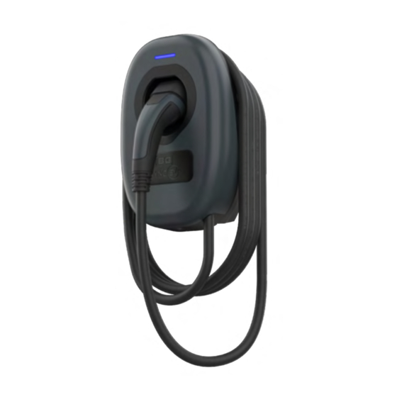
Wall Charger 2
Installation
Guide
7.4kW TETHERED SINGLE PHASE :
EVWC2T7G (7.4KW / WI-FI / LAN)
EVWC2T7GG (7.4KW / WI-FI / LAN / 4G)
click to navigate directly to the page
Commercial Installation & Commissioning
Contents
Introduction / Box contents
Safety information
Installation & testing
Troubleshooting
Domestic Commissioning
Stage 1 (Installer app)
Domestic Commissioning
Stage 2 (User app setup)
Technical
syncev.co.uk
EVWC2T7G EVWC2T7GG V2 0823 GJW
Advertisement
Table of Contents

Related Manuals for SyncEV BG EVWC2T7G

Summary of Contents for SyncEV BG EVWC2T7G
- Page 1 Wall Charger 2 Installation Guide 7.4kW TETHERED SINGLE PHASE : EVWC2T7G (7.4KW / WI-FI / LAN) EVWC2T7GG (7.4KW / WI-FI / LAN / 4G) Contents click to navigate directly to the page Introduction / Box contents Safety information Installation & testing Troubleshooting Commercial Installation &...
-
Page 2: Box Contents
Introduction This guide is intended for use by competent electrical installers to explain basic requirements and options to be considered when installing a BG SyncEV charger. The unit is designed for installations inside or outside, the advanced safety technology we have built into the unit ensures its safe usage. -
Page 3: Safety Information
Safety information Warning: The supplied BG SyncEV charger is manufactured to be safe without risk provide they are installed correctly, used, and maintained in accordance with the manufacturers recommendations and installed by a competent electrical installer in accordance with national and local regulations and legislation applicable at the time of installation, e.g. -
Page 4: Earthing Requirements
fault loop impedance values cannot be met. This will be in compliance with the current BS7671 Amendment 2 Wiring Regulations. To conform with BS 7671, on occasions a two pole MCB/RCD or other means of isolation may be required. Important note: A DC Leakage fault in the vehicle may “blind”... - Page 5 of TT/TN-S and TN-C-S), this is important where cable length may enable charging inside or outside of a building/garage where the vehicle is within touch distance. Where certain conditions dictate an earth electrode must be used it shall be independent from the distributors earth system with no direct interconnection (the incoming supply SWA protective earth should be isolated from the...
-
Page 6: Surge Protection
Surge protection Guidance on requirements for surge protection devices given In BS7671: section 443. The EV charger is protected against transient over voltages (+/-2kV Line-Earth and +/-1kV Line- Line as a requirement of EN 61000-6-1), a direct lightning strike carries a current of 30~ 200kA the EV charger’s internal protection would provide little or no protection in such an event, likewise nor would an SPD rated less than 30kA. - Page 7 Isolation and switching for safety and maintenance To ensure the EV charger can be “turned off” to enhance security and enable maintenance activities, a two pole isolator (or DP RCD or RCBO) suitably rated must be installed within the customer’s property. An isolator switch is a mandatory requirement for “new builds”, but optional for existing dwellings (at customer’s request), the switch should be...
-
Page 8: Installation Requirements
Installation requirements The EV charger is suitable for installation inside and outside on a solid wall or structure. The installer should consult with the building owner to establish their preferred installation location. This should take into consideration the length of charging cable and risk of vehicle impact etc. - Page 9 The EV charger is suitable for bottom or rear cable entry, if using rear cable entry ensure the included 25mm rubber grommet is used to maintain the IP rating. If using SWA cable the included 25mm compression gland is NOT suitable, an alternative gland will be required.
- Page 10 Load balancing If load balancing is required, a CT clamp should be used for correct balancing. One BG SyncEV CT clamps, EVA120CT1, is supplied in the box with this charger. This should be fitted around the incoming power to the main fuse and the correct max load (A) to be entered during setup and installation steps.
- Page 11 Final Electrical testing To meet the BS7671:2018 (18th edition) requirements for testing of an electrical installation, the following tests and checks shall be performed by a competent electrical installer before during and after a BG SyncEV charger is installed: • A visual inspection of the installation including the existing electrical installation.
- Page 12 • A test of the mechanical operation of residual current devices (RCD’s). • A test to confirm the operation of residual current devices (RCD’s) is within stipulated time scales (at the rated current and at five times the rated current operating current). •...
-
Page 13: Electrical Installation
Electrical Installation Isolate the power Use the included hole template to drill fixing holes 110 mm Return to Contents... - Page 14 Drill base for required cable entry. Suitable for 16-32mm hole size. If using rear entry, ensure included 25mm grommet is used Left for Right for rubber/ SWA cable flex cable Ensure the supplied washers are used to maintain IP rating Return to Contents...
- Page 15 Ensure correct polarity when making incoming power connections 3 pin plug: N - Blue E - Yellow/Green L - Brown Ensure supplied cord grip is fitted on incoming power cable if using bottom cable entry location Return to Contents...
- Page 16 Ensure Power connector is fully inserted then slide clip to secure For dynamic load balancing, insert wires into the small connector If using external 485 meter, then dip switch 2 needs to be changed to ‘On’ ‒ 485A ‒ 485B Return to Contents...
- Page 17 Plug connector into PCB, ensure correct polarity Fix charger to the base ensuring correct torque settings T25S Security Torx 2.5 Nm Return to Contents...
- Page 18 Snap front cover trim into place Fit locking screw to secure cover Return to Contents...
-
Page 19: Troubleshooting
Troubleshooting For further information, or to refer to our FAQs, please visit our website: www.syncev.co.uk The status of the EV charger can be identified by referencing the colour shown on the LED indicator: • Solid Blue – Standby – Charger has power and is connected to the network. - Page 20 Commercial / Workplace / Fleet installation & commissioning 4 simple steps: CONTACT Email workplace@syncev.co.uk with the charge-point owner contact details CONNECT Install the charge-points CONFIGURE Set the configurations in the BG SyncEV installer app and connect all chargers to the internet COMPLETE Pass the charger details to the charge-point owner...
- Page 21 • Model and charger ID (for every charger in the installation) • Contact details for the charge-point owner: • Company name • Name of charge-point manager • Site address • Telephone number for charge-point manager • Email address for charge-point manager Our Commercial Team will contact the charge-point owner to carry out the quick and...
- Page 22 Domestic Commissioning Stage 1 of 2 INSTALLER APP - Download the ‘BG SyncEV Installer’ app by clicking this link Also available from the Installer Portal on the syncev.co.uk website, or using the QR code opposite. Upon powering the charger, the status indicator light will show Yellow.
- Page 23 1. Ensure Bluetooth is active on your device. Open the BG EV Charging App and select the Charger ID Code as shown on the charger identification label. 2. Then enter the password shown on the identification label. Return to Contents...
- Page 24 – 3. Select ‘Monta’ - this is the included app. ‘EV.Energy’ and ‘SyncEV’ are alternative options (additional costs may be incurred). ‘Manual’ can be used for other alternative back offices. If unsure, choose ‘Monta’. 4. Charge Mode: ‘APP’ for smart charging via the consumer App (see next page);...
- Page 25 – 7. Dynamic Load management: If dynamic load management is required then toggle right and select Clamp Configuration. 8. Home Max Current: For load balancing this should be the same or less than the main fuse rating. EV charger will reduce its charging rate to limit the total home load to be under the limit.
- Page 26 9. Check the shown electrical measurements match measured readings. This will allow checking the Load management CTs are fitted correct orientation. Press Next to continue 10. Choose between Wi-Fi, 4G and LAN. • For Wi-Fi select the SSID network name and enter password.
- Page 27 11. On LAN the charger will default to DHCP. If static IP is required for the network connection, set the option “Manually Set Static IP Address” to OFF and a manual IP address can be entered. 12. Press next to start network connection, the charger will attempt a network connection, If successful will then reboot to complete an RCD and function check.
- Page 28 In less than 2 minutes, the indicator should turn from Yellow to Blue to confirm network connection. If the charger continues to show yellow, power cycle (switch off/on at fuse board) and reconnect via the app to check the settings are correct. If still unable to connect to the network but need to use the charger then change the Charge Mode to ‘Plug and Charge’...
- Page 29 Domestic Commissioning Stage 2 of 2 1. Download the Monta smart app: Apple app store click here Google play store click here or search for ‘Monta EV charging’ on STEP 3 STEP 3 Apple app store or Google Play 2. Using your smart-phone scan the unique Monta QR Code on the ‘Quick Start Guide’...
- Page 30 4. Create an account using your customers phone number or social logins (Apple/ Google/Microsoft) STEP 5 FOLLOW THE STEPS TO CONNECT YOUR CHARGE POINT TO MONTA Name your charge point and set the location. 5. Connect the EV charger to Monta - name the charge-point and set the location 05/05/202 05/05/202...
- Page 31 When you reach this step, your charge point is con- nected and you can use Monta to start charging. 6. Successful connection - When you reach this step, your charge-point is connected and you can use Monta to start charging Need help with the app? Contact Monta customer support through the app 05/05/2022 16...
-
Page 32: Technical Information
Technical information Environmental Protection This symbol is known as the “Crossed- out Wheelie Bin Symbol”. When this symbol is marked on a product or battery, it means that it should not be disposed of with your general household waste. Some chemicals contained within electrical/electronic products or batteries can be harmful to health and the environment. - Page 33 1. Notification of any defect is given to BG SyncEV as soon as reasonably practicable after becoming apparent, and the products then returned to BG SyncEV. 2. The products have only been operated under normal operating conditions and have only been subject to normal use.
-
Page 34: Technical Data
Technical data CODES : EVWC2T7G (7.4KW / WI-FI / LAN) EVWC2T7GG (7.4KW / WI-FI / LAN / 4G) TYPE : TETHERED SOCKET / PLUG : TYPE 2 PLUG KW : SINGLE PHASE : 7.4KW, 32A MODE 3 MIN CHARGE CONFIGURABLE, 6 - 32A... - Page 35 INDICATOR MODES : BLUE - STANDBY, FLASHING BLUE - PREPARING, GREEN - CHARGING, YELLOW - NO NETWORK, RED - ERROR HOUSING : UV STABILISED POLYCARBONATE WALL FIXING : 4 POINT WITH HORIZONTAL AND VERTICAL ADJUSTMENT, SUPPLIED FIXING HOLE TEMPLATE. FIXING HOLE CENTRES : 110 HORIZONTAL, 145 VERTICAL (MM) IP / IK RATING : IP55 / IK10...
- Page 36 SUPPLIED 1x EVA120CT1 LOAD MANAGEMENT KIT, ACCESSORIES : 5x BASE FIXING WASHERS, 5x ASSEMBLY LID BOLTS, 1x BLANKING PLUG AND 1x 25MM COMPRESSION GLAND, USER-SIDE CONNECTOR, CORD GRIP AND 2x CORD GRIP ASSEMBLY SCREWS DIMENSIONS (MM) : 305 (H) x 201 (W) x 115 (D) ADDITIONAL : ANTI TAMPER DETECTION - 2 LAYER PROTECTION, BLUETOOTH TO...
-
Page 37: Technical Support
Technical support Need help with the app? Contact Monta customer support through the app or via the website Monta.com Need help with the charge-point? Contact BG SyncEV technical support at: support@syncev.co.uk or via the website at www.syncev.co.uk BG SyncEV is a trading name of Luceco PLC. Luceco PLC –...
Need help?
Do you have a question about the EVWC2T7G and is the answer not in the manual?
Questions and answers