
Related Manuals for Deye GB-SL10K-EU


Summary of Contents for Deye GB-SL10K-EU
- Page 1 ALL IN ONE ESS GB-SL5K-EU GB-SL6K-EU GB-SL8K-EU GB-SL10K-EU GB-SL12K-EU GB-SL15K-EU GB-SL20K-EU User Manual...
-
Page 2: Table Of Contents
Contents 1. Safety Introductions ………………………………………………… 2. Product instructions 01-05 ………………………………………………… 2.1 Product Overview 2.2 Product Size 2.3 Product Features 2.4 Basic System Architecture 3. Installation 05-26 …………………………………………………………… 3.1 Parts list 3.2 Mounting instructions 3.3 Battery connection 3.4 Grid connection and backup load connection 3.5 PV Connection 3.6 CT Connection 3.6.1 Meter Connection... - Page 3 Contents may be periodically updated or revised due to product development. The informa�on in this manual is subject to change without no�ce. The latest manual can be acquired via service@deye.com.cn 1. Safety Introduc�ons · This chapter contains important safety and opera�ng instruc�ons. Read and keep this manual for future reference.
-
Page 4: Product Overview
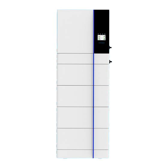
2.1 Product Overview Inverter 1: Inverter indicators 7: Ba�ery input connectors 13: DRM port 2: LCD display 8: PV input 14: BMS port 3: Func�on bu�ons 9: Func�on port 15: RS485 port 4: Power on/off bu�on 10: Meter port 16: Grid 5: DC switch 11: Parallel port 17: Load... -
Page 5: Product Size
High Voltage Control Box 1: High Voltage DC switch 2.2 Product Size Inverter Size High Voltage Control Box Size - 03 -... -
Page 6: Product Features
Ba�ery Module Size Ba�ery Base Size 2.3 Product Features - 230V/400V Three phase Pure sine wave inverter. - Self-consump�on and feed-in to the grid. - Auto restart while AC is recovering. - Programmable supply priority for ba�ery or grid. - Programmable mul�ple opera�on modes: On grid, off grid and UPS. - Configurable ba�ery charging current/voltage based on applica�ons by LCD se�ng. -
Page 7: Basic System Architecture
2.4 Basic System Architecture The following illustra�on shows basic applica�on of this inverter. It also includes following devices to have a complete running system. - Generator or U�lity - PV modules Consult with your system integrator for other possible system architectures depending on your requirements. - Page 8 GB-LBS and GB-L Base package GB-LBS(high voltage GB-L Base x1 ECOM Cable2.0 x1 Wall Fixing Plate x2 control box) x1 Expansion screws Screw(M4*8) x8 Box fixing plate x4 Movable handle x2 Screws(M4*12) x8 (M6*100) x2 GB-LM4.0 ba�ery package GB-LM4.0 x1 Box fixing plate x4 Screws(M4*12) x8 3.2 Moun�ng instruc�ons...
- Page 9 3.3 Ba�ery connec�on Inverter Inverter Battery Port High Voltage Control Box Ba�ery Pack Battery Port - 07 -...
- Page 10 3.3.1 Install the Ba�ery Installa�on Place Requirement · Installed on the surface with enough dryness, horizontal and flat, and has sufficient carrying capacity. (For example, concrete or masonry). · The al�tude of the installa�on loca�on must not be higher than 2000 meters. (The output power of the ba�ery will decrease with the height of the al�tude).
- Page 11 A�en�on: · Because the DC cable or connector on the ba�ery system may cause electric shock or very dangerous life,do not contact the end of the non-insula�ng cable. · If the ba�ery module incorrectly li�s or falls in the process of transporta�on or installa�on, it may cause the risk of injury due to the weight of the ba�ery module.
- Page 12 2. Stack the corresponding connec�on ports at the bo�om of the ba�ery module. The number of stackable ba�ery modules for a single ba�ery system ranges from 2 to 6. 3. Take out the high voltage box, and install the wall fixing plate on the pre-moun�ng hole of the high voltage box with M4*8 screws.
- Page 13 4. Finally, install the high voltage box to the top layer of the ba�ery module. 5. Use M4*12 hex socket screws to install the box fixing plate between the base and the ba�ery module, between the ba�ery modules, between the ba�ery module and the high voltage box as well.
- Page 14 6. Place the high voltage box on one side of the wall, mark the posi�ons of fixing holes, drill two holes in the wall with a depth of 100-110mm using the electrical drill, secure the high voltage box to the wall and install expansion bolts in the holes with a proper hammer. Selec�on of installa�on sites The installa�on loca�on is recommended to meet the size requirements of the figure below: 10mm≤...
- Page 15 3.3.2 Func�on port defini�on Inverter Meter Parallel_1 Parallel_2 BMS1 BMS2 RS485 1 2 3 4 5 6 7 8 9 10 1112 1 2 3 4 5 6 7 8 9 10 1112 SHUT DOWN Meter: for energy meter communica�on. Parallel_1: Parallel communica�on port 1.
- Page 16 3.4 Grid connec�on and backup load connec�on · Before connec�ng to grid, please install a separate AC breaker between inverter and grid. Also, it is recommended that installs an AC breaker between backup load and inverter.This will ensure the inverter can be securely disconnected during maintenance and fully protected from over current.
-
Page 17: Pv Connection
Be sure that AC power source is disconnected before a�emp�ng to wire it to the unit. 3. Then, insert AC output wires according to polari�es indicated on the terminal block and �ghten terminal. Be sure to connect corresponding N wires and PE wires to related terminals as well. 4. - Page 18 PV2+ PV2- PV1+ PV1- 3.5.1 PV Module Selec�on: When selec�ng proper PV modules, please be sure to consider below parameters: 1) Open circuit Voltage (Voc) of PV modules can not exceed max. PV array open circuit voltage of inverter. 2) Open circuit Voltage (Voc) of PV modules should be higher than min. start voltage. 3) The PV modules used to connected to this inverter shall be Class A ra�ng cer�fied according to lEC 61730.
-
Page 19: Ct Connection
3.6 CT Connec�on GRID 1 2 3 4 5 6 7 8 9 10 1112 Black wire White wire Arrow pointing inverter Grid *Note:when the reading of the load power on the LCD is not correct, please reverse the CT arrow. - 17 -... - Page 20 3.6.1 Meter Connec�on GRID Meter Parallel_1 Parallel_2 Three-Phase Smart Meter RS485A Grid RS485B Three-Phase Smart Meter (1,4,7,10) (3,6,9,10) RS 485 CHINT meter CHNT DTSU666 GRID Meter Parallel_1 Parallel_2 RS485B RS485A 1 2 3 4 5 6 7 8 Eastron Grid (1,2,3,4) (5,6,7,8) B A G...
- Page 21 GRID Meter Parallel_1 Parallel_2 AC Breaker RS485B RS485A Home Load AC Breaker Three-Phase Smart Meter Grid Red line Black line Red line Black line Red line Note: the arrow direction towards the inverter Black line 5 8 10 4 6 7 9 Three-Phase Smart Meter (2,5,8,10) Phase A current =5.000A...
- Page 22 GRID Meter Parallel_1 Parallel_2 AC Breaker Home Load AC Breaker NA LA L1 L2 L3 N Grid S1 S2 S1 S2 S1 S2 Black line Red line Black line Red line Black line Note: the arrow direction towards Red line the inverter 9 1 0 11 1 2 1 3 1 4 1 5 1 6 1 7 1 8 1 9 2 0 Eastron...
-
Page 23: Earth Connection(Mandatory)
Note: When the inverter is in the off-grid state, the N line needs to be connected to the earth. Note: In final installa�on,breaker cer�fied according to IEC 60947-1 and IEC 60947-2 shall be installed with the equipment. 3.7 Earth Connec�on(mandatory) Ground cable shall be connected to ground plate on grid side this prevents electric shock if the original protec�ve conductor fails. -
Page 24: Wiring System For Inverter
3.9 Wiring System for Inverter - 22 -... -
Page 25: Wiring Diagram
3.10 Wiring diagram - 23 -... - Page 26 Backup Load ① AC Breaker for backup load GB-SL5K-EU: 100A AC breaker GB-SL6K-EU: 100A AC breaker GB-SL8K-EU: 100A AC breaker GB-SL10K-EU: 100A AC breaker GB-SL12K-EU: 100A AC breaker GB-SL15K-EU: 100A AC breaker GB-SL20K-EU: 100A AC breaker ② AC Breaker for grid...
-
Page 27: Typical Application Diagram Of Diesel Generator
① AC Breaker for backup load GB-SL5K-EU: 100A AC breaker GB-SL6K-EU: 100A AC breaker GB-SL8K-EU: 100A AC breaker Backup Load GB-SL10K-EU: 100A AC breaker GB-SL12K-EU: 100A AC breaker GB-SL15K-EU: 100A AC breaker GB-SL20K-EU: 100A AC breaker Remotely control signal line ②AC Breaker... - Page 28 ①③⑤ AC Breaker for grid port Ground GB-SL5K-EU: 100A AC breaker ④ GB-SL6K-EU: 100A AC breaker GB-SL8K-EU: 100A AC breaker GB-SL10K-EU: 100A AC breaker ③ GB-SL12K-EU: 100A AC breaker GB-SL15K-EU: 100A AC breaker GB-SL20K-EU: 100A AC breaker ②④⑥ AC Breaker for backup load...
-
Page 29: Operation
4. OPERATION 4.1 Power ON/OFF Once the unit has been properly installed and the ba�eries are connected well, simply press On/Off bu�on(located on the le� side of the case) to turn on the unit. When system without ba�ery connected, but connect with either PV or grid, and ON/OFF bu�on is switched off, LCD will s�ll light up(Display will show OFF), In this condi�on, when switch on ON/OFF bu�on and select NO ba�ery,system can s�ll working. -
Page 30: Lcd Display Icons
Chart 4-2 Light Meaning In addi�on to the LED lights,the ba�ery fault informa�on can be obtained through the screen and the upper computer. DEYE can also read these informa�on through remote WLAN connec�on. 5. LCD Display Icons 5.1 Main Screen The LCD is touchscreen, below screen shows the overall informa�on of the inverter. - Page 31 5.1.1 LCD opera�on flow chart Solar Page Solar Graph Grid Page Grid Graph Inverter Page Main Screen Battery Page BMS Page Load Page Load Graph Battery Setting System Work Mode Grid Setting System Setup Gen Port Use Basic Setting Advanced Function Device info - 29 -...
-
Page 32: Solar Power Curve
5.2 Solar Power Curve Solar This is Solar Panel detail page. ① Solar Panel Genera�on. ② PV1-V: 286V PV1-I: 5.5A PV1-P: 1559W Voltage, Current, Power for each MPPT. ② PV2-V: 286V PV2-I: 5.5A PV2-P: 1559W ③ Daily and total PV produc�on. ③... -
Page 33: Curve Page-Solar & Load & Grid
Li-BMS Mean Voltage:170.0V Charging Voltage :180.0V Batt Total Current:37.00A Discharging Voltage :160.0V Data Mean Temp :23.5C Charging current :30A Total SOC :38% Discharging current :25A Battery 1 Stand by Dump Energy:57Ah Details Data U:170V I:2.04A Li-BMS Power: 101W Charge Volt Curr Temp Energy... -
Page 34: System Setup Menu
5.4 System Setup Menu System Setup This is System Setup page. System Work Mode Battery Setting Gen Port Grid Setting Basic Advanced Device Info. Setting Function 5.5 Basic Setup Menu Basic Setting Factory Reset: Reset all parameters of the inverter. Lock out all changes: Enable this menu for se�ng Time Syncs Beep... -
Page 35: Battery Setup Menu
5.6 Ba�ery Setup Menu Battery Setting Ba�ery capacity: it shows your ba�ery bank size to Deye hybrid inverter. Batt Mode Use Ba� V: Use Ba�ery Voltage for all the se�ngs (V). Lithium Batt Capacity Batt Use Ba� %: Use Ba�ery SOC for all the se�ngs (%). - Page 36 12/08/2022 15:34:40 This page tells the PV and diesel generator power the load and ba�ery. 0.00 8.61 Signal -8.12 0.00 Generator This page tells generator output voltage, frequency, power. And, how much energy is used from generator. Power: 6000W Today=10 KWH Total =10 KWH P_L1: 2KW V_L1: 230V...
-
Page 37: System Work Mode Setup Menu
Recommended ba�ery se�ngs Torque value Battery Type Absorption Stage Float Stage (every 30 days 3hr ) Lithium Follow its BMS voltage parameters 5.7 System Work Mode Setup Menu System Work Mode Work Mode Selling First: This Mode allows hybrid inverter to sell back any excess power produced by the solar panels to 12000 Selling First... - Page 38 Solar Sell: “Solar sell” is for Zero export to load or Zero export to CT: when this item is ac�ve, the surplus energy can be sold back to grid. When it is ac�ve, PV Power source priority usage is as follows: load consump�on and charge ba�ery and feed into grid.
-
Page 39: Grid Setup Menu
5.8 Grid Setup Menu Grid Setting/Grid code selection Grid Mode:General Standard、UL1741 & IEEE1547、 CPUC RULE21、SRD-UL-1741、CEI 0-21、Australia A、 Grid Mode General Standard 0/10 Australia B、Australia C、EN50549_CZ-PPDS(>16A)、 Phase Type Grid Frequency 50HZ Grid NewZealand、VDE4105、OVE-Direc�ve R25. Set1 0/120/240 60HZ Please follow the local grid code and then choose the 0/240/120 corresponding grid standard. - Page 40 Grid Setting/F(W) FW: this series inverter is able to adjust inverter output power according to grid frequency. F(W) Droop F: percentage of nominal power per Hz Over frequency Droop F %PE/Hz For example, “Start freq F>50.2Hz, Stop freq F<51.5, Grid Set4 Stop freq F Start freq F...
-
Page 41: Generator Port Use Setup Menu
5.9 Generator Port Use Setup Menu GEN PORT USE Generator input rated power: allowed Max. power from diesel generator. Mode GEN connect to grid input: connect the diesel generator to the Generator Input GEN connect to Grid input grid input port. PORT Rated Power Smart Load Output: This mode u�lizes the Gen input connec�on... -
Page 42: Device Info Setup Menu
Advanced Function Ex_Meter For CT: when using zero-export to CT mode, the hybrid inverter can select EX_Meter For CT func�on Modbus SN Parallel and use the different meters.e.g.CHNT and Eastron. Master Paral. Set3 Slave EX_Meter For CT Meter Select No Meter CHNT Eastron 5.11 Device Info Setup Menu... -
Page 43: Limitation Of Liability
Mode III: With Smart-Load AC cable DC cable Solar Backup Load On-Grid Home Load Grid Smart Load Mode IV: AC Couple On-Grid+AC couple AC cable DC cable Solar Backup Load On-Grid Home Load Grid On-Grid Inverter The 1st priority power of the system is always the PV power, then 2nd and 3rd priority power will be the ba�ery bank or grid according to the se�ngs. - Page 44 Error code Description Solutions 1,Check the PV input polarity DC_Inversed_Failure 2,Seek help from us, if can not go back to normal state. 1,The BUS voltage can t be built from PV or battery. DC_START_Failure 2,Restart the inverter, If the fault still exists, please contact us for help 1.
- Page 45 Error code Description Solutions BUS over current. 1, Check the PV input current and battery current setting Tz_HV_Overcurr_fault 2. Restart the system 2~3 times. 3. If the fault still exists, please contact us for help. Remotely shutdown Tz_EmergStop_Fault 1, it tells the inverter is remotely controlled. Leakage current fault 1.
- Page 46 Error code Description Solutions Grid frequency out of range 1. Check the frequency is in the range of specification or not; AC_OverFreq_Fault 2. Check whether AC cables are firmly and correctly connected; 3. Seek help from us, if can not go back to normal state. Grid frequency out of range 1.
- Page 47 Under the guidance of our company, customers return our products so that our company can provide service of maintenance or replacement of products of the same value. Customers need to pay the necessary freight and other related costs. Any replacement or repair of the product will cover the remaining warranty period of the product.
-
Page 48: Datasheet
8. Datasheet Model SL5K-EU SL6K-EU SL8K-EU SL10K-EU SL12K-EU SL15K-EU SL20K-EU Battery Input Date Ba�ery Type Li-lon Ba�ery Voltage Range(V) 160~700 Max. Charging Current(A) Max. Discharging Current(A) Number of ba�ery input Charging Strategy for Li-lon Ba�ery Self-adap�on to BMS PV String Input Data Max. - Page 49 Certifications and Standards VDE4105,IEC61727/62116,VDE0126,AS4777.2,CEI 0 21,EN50549-1, Grid Regula�on G98,G99,C10-11,UNE217002,NBR16149/NBR16150 IEC62109-1/-2, NBT32004-2018, EN61000-6-1,EN61000-6-2, EMC/Safety Regula�on EN61000-6-3, EN61000-6-4 General Data Opera�ng Temperature Rande(℃) -40~60℃, >45℃ Dera�ng Cooling Smart cooling Noise(dB) ≤55 dB Communica�on with BMS RS485; CAN Weight(kg) 30.5 Size(mm) 408W×638H×237D Protec�on Degree IP65 Installa�on Style Wall-mounted...
- Page 50 9. Appendix I Defini�on of RJ45 Port Pin for BMS1 1 2 3 4 5 6 7 8 BMS1 Port RS485 Pin 485_B 485_A GND_485 CAN-H1 CAN-L1 GND_485 485_A 485_B Defini�on of RJ45 Port Pin for BMS2 BMS2 Port RS485 Pin 485_B 485_A GND_485...
- Page 51 Defini�on of RJ45 Port Pin for RS485 1 2 3 4 5 6 7 8 RS485 Pin RS485 Port Modbus-485_B Modbus-485_A GND_485 GND_485 Modbus-485_A Modbus-485_B RS232 WIFI/RS232 D-GND 12Vdc WIFI/RS232 This RS232 port is used to connect the wifi datalogger - 49 -...
-
Page 52: Appendix
10. Appendix II 1. Split Core Current Transformer (CT) dimension: (mm) 2. Secondary output cable length is 4m. Lead Outside Ver: 2.2, 2023-01-11 - 50 -... - Page 53 Add: No.26-30, South Yongjiang Road, Beilun, 315806, Ningbo, China Tel: +86 (0) 574 8622 8957 Fax: +86 (0) 574 8622 8852 E-mail: service@deye.com.cn Web: www.deyeinverter.com...
Need help?
Do you have a question about the GB-SL10K-EU and is the answer not in the manual?
Questions and answers