Table of Contents
Advertisement
Quick Links
Advertisement
Table of Contents

Related Manuals for FAS FNI MPL-302-105-M


Summary of Contents for FAS FNI MPL-302-105-M
- Page 1 FNI MPL-302-105-M IP 67 Module User Manual Page 1 of 16...
-
Page 2: Table Of Contents
Table of contents 1 Notes 1.1. Manual structure 1.2. Typography 1.3. Symbol 1.4. Abbreviations 1.5. Visual Bias 2 Security 2.1. Intended use 2.2. Installation and startup 2.3. General Security Notes 2.4. Resistance to Corrosive Substances 3 Getting Started Guide 3.1. Module overview 3.2. -
Page 3: Notes
Notes This symbol indicates a general comment. -------------------------------------------------- --------- Notice! This symbol indicates the most important safety notice. -------------------------------------------------- --------- FNI FAS Network Interface 1.4. Acronym I Standard input port PN Profinet ECT EtherCAT CIE CC_link IEF Basic EIP Ethernet/IP... -
Page 4: Security
Explain the materials used. safety This manual describes as decentralized input 2.1. Expected output modules for connection to an industrial network. usage Precautions! Installation and start-up may only be carried out by 2.2. Install trained and specialized personnel. A qualified and start individual is one who is familiar with the installation and operation of the product and has... -
Page 5: Getting Started Guide
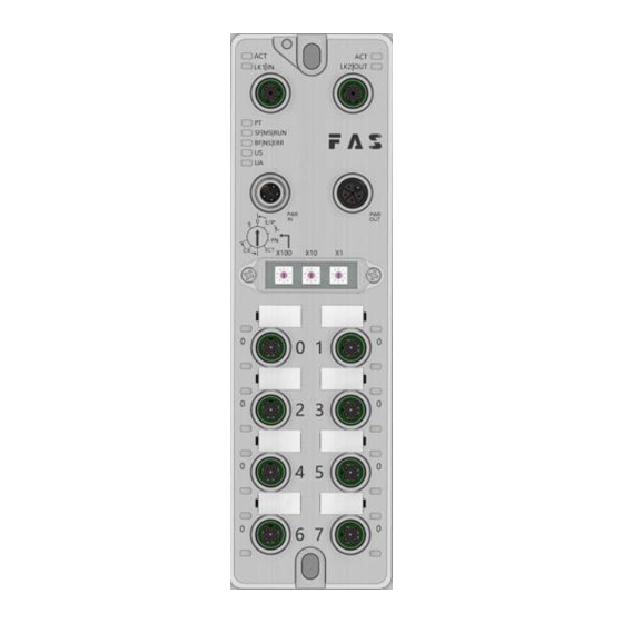
3. Getting Started Guide 3.1. Module overview 1 Mounting hole 8 Port 5 15 Port Identification Board 2 Network port 2 Status 9 Port 7 16 Power input port indicator 3 Network port 2 10 Port 6 17 Module indicator 4 Power outlet 11 Port 4 18 Network port 1... -
Page 6: Mechanical Connection
3. Getting Started Guide 3.2. Mechanical connection The modules are attached using 2 M6 bolts and 2 washers. Isolation pads are available as accessories. 3.3. Electrical connections 3.3. 1 Power interface(L-code) Definition of power input port Definition of power outlet Function Describe +24V... - Page 7 I/O-Port(A-code) 3.3.3 Function +24V,1A Enter /output Enter /output 1. For digital sensor input, please follow the input guidelines of EN61131-2, Type 2. 2. The maximum output current of pins 2 and 4 is 2A. The total current of the module is less than 9A. 3.
-
Page 8: Technical Data
4.Technical data 4.1. size 4.2 Mechanical data Shell material Die-cast aluminum case, pearl nickel plated Housing class according to IEC 60529 IP67 (only in plug-in or plug-in style) Power interface L-Code (Male and Female) Input port/output port M12, A-Code (8*female) Size(W*H*D) 65mm*222mm*25.8mm Installation type... -
Page 9: Network Port
4.5 Network port 2 x 10Base-/100Base-Tx Port M12 ,D-Code Port connection Shielded twisted pair, min. STP CAT 5/STP IEEE 802.3 Compliant Cable Types CAT 5e 10/100 M bit/s Ddata transfer rate Maximum cable length 100m Half condition/full condition(IEEE 802.3- Flow control PAUSE) 4.6 Function indicator Green... - Page 10 Red light double flash Application monitoring timeout Page 10 of 16...
- Page 11 I/O port status State Function Closure The status of Pin4 input or output is 0 Yellow The status of Pin4 input or output is 1 Port configured as input: short between Pin1 and 3 Flashing red Port configured as output: Pin4 overcurrent Closure Port configured as output: short circuit between Pin1 and 3 Yellow...
-
Page 12: Module Configuration
5 Integrated Module configuration 5.1.1 Restore factory settings 1. Power off the device, dial 900; 2. Power on the device and wait for 10 seconds; 3. Power off the device, dial the code to the state before setting 5.1.2 Node address configuration The node address is assigned by PLC: DIP address X100=4 X10=0 X1=0 Manual assignment of node address: DIP address X100=4, node number X10=tens X1=ones For example: X100=4, X10=2, X1=5, the node number is 25. -
Page 13: Data Mapping
5.2 Data mapping process output data 位 ( Bit) Function Port7 Port6 Port5 Port4 Port3 Port2 Port1 Port0 PIN4 output Port7 Port6 Port5 Port4 Port3 Port2 Port1 Port0 PIN2 output Da t a de s c r i p t i o n ( b i n a r y ) : 0 = o f f 1 = o n process input data 位... - Page 14 5.3.1 OMRON NX1P2 Sysmac Studio Integrated (ECT) 1 、 Install the ESI file: double-click EtherCAT in the configuration and settings--right- click the master device--select "Show ESI library", and select the ESI file in the pop-up window to install Page 14 of 16...
- Page 15 2、Configure the module to the EtherCAT network: find the FieldBus Modules in the toolbox on the right, find the module model icon and double-click to add it to the network 3 、The PLC goes to online mode, right-click the master device, and write the node address of the slave device 4 、Variable mapping: Select the configured node in the I/O mapping, fill in the name of the variable, and the configuration is complete! .
-
Page 16: Appendix
Appendix 6.1. Included FNI MPL contains the following components materials · I/O- block · 4 blind plugs M12 · Ground bus · Thread M4x6 · 20 tags 6.2. Order code 6.3 Ordering Information Product order code Order code FNI ECT-332- 105-M 006E11 Page 16 of 16...
Need help?
Do you have a question about the FNI MPL-302-105-M and is the answer not in the manual?
Questions and answers