
Related Manuals for EG4 EG4-LL-S


Summary of Contents for EG4 EG4-LL-S
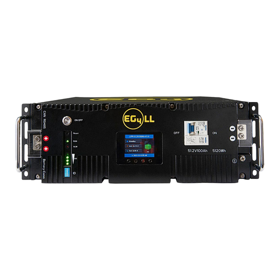
- Page 1 USER MANUAL EG4®-LL 48V 100AH Rack-Mounted Battery © 2023 EG4 Electronics, LLC. All rights reserved. Version 2.1.0 | Information subject to change without notice.
-
Page 2: Table Of Contents
5.3.1 Connecting multiple batteries in parallel ....................13 5.3.2 Communication Cable Pinout and DIP Switch ID Tables ................. 13 Installing with Different EG4 ® Battery Models ....................15 Battery Operation ..............................16 LCD Screen ..............................16 6.1.1 Button description ..........................16 6.1.2... - Page 3 BMS Protection ............................24 Troubleshooting ............................. 25 7.2.1 Alarm Description and Troubleshooting ....................25 Battery End of Life ............................26 EG4® Warranty ............................... 27 Warranty Exclusions ............................27 Technical Specifications ............................28 Technical Specifications Table ........................28 Battery Performance Curves........................... 30...
-
Page 4: Abbreviations
1 Abbreviations • A — Amp(s) • Ah — Amp hours • AC — Alternating Current • AHJ — Authority Having Jurisdiction • ANSI — American National Standards Institute • AWG — American Wire Gauge • BMS — Battery Management System •... -
Page 5: Safety
2 Safety 2.1 Safety Instruction Before any work begins, carefully read all safety instructions, and always observe them when working on or with the battery. The installation must follow all applicable national or local standards and regulations. Consult with your AHJ to obtain the proper permits and permissions before installation. Incorrect installation may cause: •... -
Page 6: Brief Introduction
7. Battery is designed to stop charging at 32°F. If charging current is observed when the internal battery temperature is below 32°F, disconnect battery immediately and consult manufacturer. DISCLAIMER EG4® reserves the right to make changes to the material herein at any time without notice. You may refer to the EG4® website at www.eg4electronics.com for the most updated version of our manual. -
Page 7: Battery Overview
19-inch cabinet and communicates with external devices via CAN/RS485 as well as with other EG4® batteries via RS485. The modules can be connected in parallel to meet expansion requirements. Inter-battery communications support a maximum of 64 modules for the 6 DIP switch model or 16 modules for the 4 DIP switch model. -
Page 8: Battery Diagram
4.2.1 Battery Diagram Item Description Remarks Positive terminal M6 bolt (x2) RS485 port RS485 communication interface Pin 1 & Pin 8 ‒ RS485_B Pin 2 & Pin 7 – RS485_A CAN port CAN communication interface Pin 4 – CAN_H Pin 5 – CAN_L ALM LED Alarm status LED RUN LED... -
Page 9: Emergency Stop (Rsd, Ess Disconnect)
4.2.2 Emergency Stop (RSD, ESS Disconnect) The optional ESS disconnect can be used to shut down all batteries and inverters (if equipped) with the push of a button. This integrated safety feature ties directly into the battery communication system via an open Battery-Com port using a standard Cat-5/6 ethernet cable. -
Page 10: Installation
Environmental Factors The environment you store your EG4® battery in can greatly affect the health of the battery. For best results, the temperature should remain moderate, between 41°F and 68°F (5°C and 20°C). Keep the battery away from locations where it may get wet or locations with high humidity (>55%). Store the... -
Page 11: Requirements For Installation
5.2.2 Requirements for Installation Warning Do not put EG4® 48V-LL batteries in series. • The BMS and internal components are not designed to handle this setup, which could cause the modules to fail. • Avoid exposing batteries to conductive materials, such as water, strong oxidizers, and strong acids. -
Page 12: General Installation
Tools needed for installation The tools required may vary depending on how you choose to mount your battery. Typically, the following items are needed to install the battery into an EG4® battery rack solution or general racking. 1. 10mm socket and ratchet 2. -
Page 13: Installation In Eg4® Battery Rack
Warning Do not ground rack/cabinet or door to negative or positive bus bars! In this image, there are 6 EG4®-LL 48V 100Ah batteries wired in parallel. This battery bank still maintains the appropriate 48V needed for a system. However, the Amp hour rating of this bank has increased to 600Ah. -
Page 14: Battery Communications
5.3 Battery Communications Each EG4® battery is designed with you in mind, displaying as much information as possible in the simplest manner. EG4® Electronics includes the option of connecting the battery to PC software to monitor the module status. This allows you to see and understand exactly what the battery is doing as well as troubleshoot if problems arise. - Page 15 Communication Cable Pinout & Table* Description RS485-B RS485-A CAN High CAN Low RS485-B RS485-A CAN Ground (optional) CAN High CAN Low DIP switch ID table – 4 Pin *Pinouts are for battery side, please refer to your system manual for pinout configuration on system end. DIP switch ID table –...
-
Page 16: Installing With Different Eg4 ® Battery Models
5.4 Installing with Different EG4 ® Battery Models EG4® LL-V2 batteries can communicate with all EG4 ® 48V server rack modules. However, you will need to apply the proper firmware to any LL-V1 and/or Lifepower4 modules before installation. Please visit http://www.eg4electronics.com/downloads... -
Page 17: Battery Operation
6 Battery Operation 6.1 LCD Screen Each module has a built-in HD LCD touch screen used to display important information about the cells including voltage, current, temperature, SOC, and others. 6.1.1 Button description There are 4 function buttons below the display with detailed descriptions, as shown in the table below. Description Down Return... -
Page 18: Cell Information
6.1.3 Cell Information Check individual cell voltage by pressing the “Enter” button on the main page of the LCD screen (shown in mV). There are 2 pages. Pressing “Up” and “Down” changes the page. Page 2 Page 1 6.1.4 Temperature Information Press "Enter"... -
Page 19: Bms Tools Installation And Interfacing
4. Select the corresponding RS485 program or CAN program, and press Enter. RS485 Protocol Inverter CAN Protocol Inverter P01-EG4 P01-GRW Growatt P02-GRW Growatt P02-SLK Sol-Ark P03-LUX Luxpower P03-DY Deye P04-SCH Schneider P04-MGR Megarevo P05-VCT Victron P06-LUX Luxpower 5. Press the “Return” key to return to the main interface. - Page 20 2. Once downloaded, locate the file. (This is typically in the Downloads folder.) 3. Right click on the folder and click “Extract All.” Verify the location the file will be extracted to for future reference. Check the box “Show extracted files when complete” and click on “Extract.”...
- Page 21 4. Open the folder to access BMS_TOOLS. Right click and click “Run as administrator.” You may see a popup for Microsoft Defender appear. Click “More info,” and then click “Run anyway.” 5. You will be brought to the main page of BMS Tools.
-
Page 22: Interfacing With Bms Tools
6.3.2 Interfacing with BMS Tools 1. Press the ON/OFF button on the battery to power off the BMS. 2. Set the DIP switch ID address of the battery to Address 64 (6-pin DIP, see image A) or Address 16 (4-pin DIP, see image B). -
Page 23: Interface Menu Definition
7. Open BMS Tools. Under “Monitor Status,” verify “COM” matches the battery COM from the previous “Ports” list. Verify “Baud Rate” is set to 9600, and “PACK ID” is set to 16, then click “SearchDevice.” After about 30 seconds, BMS Tools will begin the monitoring process and pull real-time data from the BMS. -
Page 24: Battery Charging
Interface menu definition Item Definition Real-time data and status monitoring of the BMS (see Section 7.2.1: BMS Monitoring Warning and protect status definitions table) BMS parameter setting management (restricted, unauthorized BMS Parameter changes will void warranty) Control state management of BMS (restricted, unauthorized BMS Control changes will void warranty) BMS Datalog... -
Page 25: Troubleshooting, Maintenance & Disposal
This protection also aids in keeping the battery and battery cells operational for a greater number of life cycles. Each EG4®-LL battery is specifically configured to ensure peak performance and operation with any system. -
Page 26: Troubleshooting
Current protection The BMS is designed to constantly monitor the charge/discharge amperage and has built-in safeguards against exceeding specific parameters. These include built-in timers that shut off quickly in the event of short circuits, extremely high amperage and delayed shut down for amperage that is only slightly above the maximum capacity. -
Page 27: Battery End Of Life
There are several websites and organizations that will accept this battery to recycle at little to no cost to the user. At EG4®, we understand that we are working with customers across the United States and the world. Our recommendation is to go online and search the... -
Page 28: Eg4® Warranty
LFP batteries. We recommend calling ahead of time to ensure that the location is still open and accepting material. If, however, users are unable to locate a disposal location safely, EG4® is here to help. Before dumping the battery or disposing of it incorrectly, please contact our customer service team for assistance. -
Page 29: Technical Specifications
9 Technical Specifications 9.1 Technical Specifications Table Module Operating Parameters Parameter Recommended Setting on System 51.2V Voltage 100Ah Capacity Charging Voltage 56.8V 56.2V (+/-0.2V) (Bulk/Absorb) 54V (+/-0.2V) Float 44.8V 47-45.6V (start high, lower as needed) Low DC Cutoff 100A (Max. continuous) 30-50A Charging Current 100A (Max. - Page 30 General Specifications Parameter Spec Condition Cell Balance 120mA Passive Balance Cell Voltage Difference >40mV Measuring Range -40°F ‒ 212°F Temperature Accuracy Cycle Measurement (-40°C ‒ 100°C) Voltage Accuracy 0.5% Cycle Measurement For Cells & Module Current Accuracy Cycle Measurement Measuring Range -200A - 200A Integral Calculation Power Consumption Sleep &...
-
Page 31: Battery Performance Curves
9.2 Battery Performance Curves... - Page 32 Notes...
- Page 33 CONTACT US Email: support@eg4electronics.com Phone: +1 (903) 609-1988 Website: www.eg4electronics.com © 2023 EG4 Electronics, LLC. All rights reserved. Version 2.1.0 | Information subject to change without notice.
Need help?
Do you have a question about the EG4-LL-S and is the answer not in the manual?
Questions and answers