Table of Contents
Advertisement
Quick Links
Advertisement
Table of Contents

Related Manuals for ep ESL122


Summary of Contents for ep ESL122
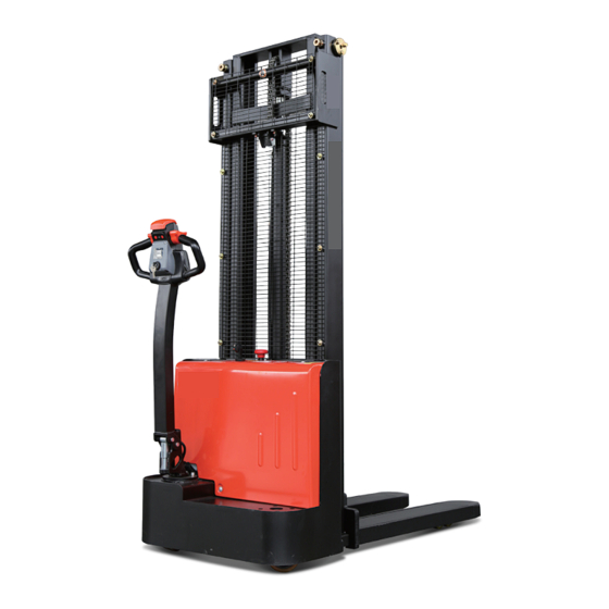
- Page 1 Operation Manual ESL122 Original Instruction Part No.508000004526 V1 12/2020...
- Page 2 Preface Thank you for buying our products. The manual will show you the way of correctly using the truck as well as relevant preventive maintenance and safety operation. The truck should be operated only by well-trained professionals and by no means by non-working personnel. Operators are supposed to read through the manual before actually operating the truck.
- Page 3 Intended use The lift truck is designed for transporting and stacking the loads stated in the load capacity diagram. In particular we refer to: • the safety rules of your trade association. • the special measures required for driving onpublic roads in accordance with the StVZO (Road Traffic Licencing Regulations).
- Page 4 Driving The electronic control unit ensures comfortable use and lower costs. Precise control of driving speed. Jolt-free starting and smooth acceleration to maximum speed. Simply release or turn the drive direction switch to brake. Booster circuit prevents the truck rolling back when starting on a gradient. Hydraulics Gear pump driven by fully enclosed air-cooled motor.
- Page 5 Legal requirements for marketing Declaration We declare that the Industrial truck: according to this operation manual Type: according to this operation manual complies with the most recent version of Machinery Directive 2006/42/EC. Personnel authorised to compile the technical documents: See EC/EU Declaration of Conformity EC/EU Declaration of Conformity The manufacturer declares that this industrial truck complies with the EC Machinery Directive and the provisions of other applicable EC/EU directives effective at the time of sale.
-
Page 6: Table Of Contents
Table of contents A Identification points and data plates ..................A1 B Operation ..........................B1 1.1 Utilization safety specification.....................B1 1.1.1 EN standards ........................B2 1.1.2 Conditions for application ....................B3 1.1.3 Stability ...........................B3 2.2 Display and manipulation ....................B4 2.2.1 Control handle .........................B4 2.2.2 Key switch ........................B5 2.2.3 Display instrument ......................B5 2.3 Truck use and operation .....................B6 2.3.1 Preparation for use ......................B6... -
Page 7: A Identification Points And Data Plates
Identification points and data plates Have the nameplates of a truck fixed its main body and alarming labels pasted on its outer cover. Should any nameplate or alarming label lose or be damaged, please conduct replacement immediately or contact with the sales department or corresponding agent of our company when necessary. - Page 8 Emergency stop switch The load capability chart The capacity plate gives the capacity (Q) of the truck in kg for a vertical mast. The maximum capacity is shown as a table Q (kg) with a given load centre of gravity D (in mm) and the required lift height H (in mm).
-
Page 9: B Operation
Operation 1.1 Utilization safety specification Fig0000-00016OM Applicable environment Don’t use the truck in Don’t use the truck in non- temperature for lithium-ion rainwater. position. battery: -10 °C - 40 °C NOTE The truck can by no means be used under the temperature lower than -10 °C for a long time, or in refrigeratory or under the condition that such environmental factor as temperature or humidity changes extremely before special equipment is additionally installed and the permit of the manufacturer is acquired. -
Page 10: Standards
Fig0000-00182OM Don’t leave the truck before Don’t use the truck when any Don’t place any part of it is parked as regulated. non-working personnel is in the your body in any moving dangerous area. part of the truck to avoid Don’t be distracted when using the being clamped. -
Page 11: Conditions For Application
1.1.2 Conditions for application Working condition requirements: The walking, lifting and lowering devices, harness and components are IP55 dust and water- resistant. The truck's maximum operation altitude is up to 2000m. Trucks can only be operated in adequately illuminated working areas to avoid injuries. In case of insufficient light, an additional lighting equipment is needed to ensure that the driver can see properly. -
Page 12: Display And Manipulation
2.2 Display and manipulation 2.2.1 Control handle Fig0000-00069OM Lowering button Lower loading parts Lifting button Lift loading parts Drive switch Controls travel direction and speed Horn button Send out sound warning signals Through touching the button, truck drives Emergency reverse swith away from operator. -
Page 13: Key Switch
2.2.2 Key switch 1.Key switch Connect and interrupt control current. When the key rotates to gear “OFF”, the control current of the truck will be interrupted; When the key rotates to gear “ON”, the control current of the truck will be connected. Fig0000-00070OM 2.2.3 Display instrument •... -
Page 14: Truck Use And Operation
2.3 Truck use and operation 2.3.1 Preparation for use WARNING The following are inspection and preparation operations that must be implemented before the truck is put into daily use. Daily Check Items O.K.(√) Remark Check for Fluid Leakage Check operation switch, display equipment and component functions. -
Page 15: Commissioning
2.3.2 Commissioning The truck must only be operated on battery current! To prepare the truck for operation after delivery or transportation, the following operations must be performed: Check the equipment for completeness. If necessary, install the battery. Make sure that the battery cable is not damaged. Charge the battery. -
Page 16: Truck Starting
2.3.3 Truck starting 1. Release the emergency stop switch(1); 2.Turn the key switch (2) to start the truck; 3.Test the horn button(3); The truck is now operational. Put the tiller in the drive position(M) and use the drive switch to control direction and speed. REV. -
Page 17: Running, Steerving And Braking
2.3.4 Running, steering and braking 1.Running Running area Tilt the control shaft into the running area (M) and control the running direction and speed of the using the drive switch(1). (the lager the turning angle, the faster corresponding speed) NOTE When using the truck on a ramp or a uneven road, please lift the mast to prevent its bottom from colliding with the road surface. - Page 18 Keep the handle in the vertical state, and press tortoise speed button (1) and drive switch(2) at the same time, then the vehicle will move at a low speed. 2.Steering Turn the control handle (1) left or right according to the desired direction. 3.Braking Mechanical operating brake The truck is braked when the operating...
- Page 19 Emergency stop switch Press the emergency stop switch, and then all the electrically propelled functions will be interrupted. Regenerative braking Release the drive switch. The drive switch will automatically return to the initial position and the vehicle will begin to enter the regenerative braking state.
-
Page 20: Goods Picking
2.3.5 Goods picking 1.Lifting Fig2108-00024OM Keep pressing the lifting button until reaching the required lifting height 2.Lowering Fig2108-00025OM Lower the truck to the bottom through pressing the lowering button. REV. 12/2020... - Page 21 Keep the handle in the vertical state, and press creep speed button (1) and drive switch(2) at the same time, then the vehicle will move at a low speed. WARNING Goods failing to be arranged and fixed may result in accidents. NOTE To avoid shortening the service life of the oil cylinder, try not to lift the stacker mast to the...
-
Page 22: Parking The Truck Securely
The emergency lowering screw is located on the solenoid valve(3). 2.3.6 Parking the truck securely Lower the mast to the bottom; Fig2108-00026OM Turn off the key switch(2); REV. 12/2020... -
Page 23: Drive Switch
2.3.7 Drive switch The drive directions of the truck are forward (2) and reverse (1). Fig2108-00028OM 2.3.8 Loading Before lifting a load, ensure that its weight does not exceed the truck’s maximum load capacity. Refer to the rated load capacity specified on the truck’s nameplate. Ensure that the load is stable and uniform to prevent any partial spillage. - Page 24 Carrying a load DANGER Personnel must not stand under or near the mast when the load is in the raised position. DANGER Never transport a load with the forks in the raised position as the equipment may become unstable. Always drive forwards for optimum visibility. Fig2108-00029OM When carrying a load on a slope, always climb and descend with the load up-hill.
- Page 25 Setting a load down on the ground Carefully move the load into the deposit area. Lower the load until the fork arms are free. Move the forks straight back. Lift the forks a few centimeter again. CAUTION Be careful not to touch nearby loads or those behind the equipment.
- Page 26 Picking up a load at height Carefully drive the machine to the required location. Raise the forks to the height of the pallet. Carefully move the forks forward under the pallet. Lift the forks until the pallet moves away from the racking.
-
Page 27: Using The Truck On A Slope
2.3.9 Using the truck on a slope NOTE Incorrect use of the truck on slopes places stress on the traction motor, brakes and battery. Be particularly careful near slopes: Never attempt a slope with a gradient greater than that specified in the truck’s data sheet. Make sure that the ground is dry with a nonslip surface and that the route is clear. -
Page 28: Operating The Truck Without Its Own Drive System
2.3.10 Operating the truck without its own drive system If the truck has to be moved after a failure has rendered it immobile, proceed as follows: Set the emergency stop switch “OFF”. Set the key switch “OFF” and remove the key. Prevent the truck from rolling away. - Page 29 NOTE The stacker should be loaded and unloaded by specially trained personnel. Effective measures must be taken based on the specific situation to ensure the correctness and safety of measurement and loading/unloading operations. REV. 12/2020...
-
Page 30: Hoisting
2.3.12 Hoisting Remove the load before hoisting the stacker. Disconnect the power supply. Attach slings in the positions identified by the hook symbol. DANGER Personnel must not stand below or near the truck when the stacker is being lifted. Do not sling the truck by the control handle. REV. -
Page 31: C Battery Use And Maintenance
Battery use and maintenance 1.1 Handling the battery 1.1.1 Battery charging Precautions The vehicle must be parked in a wellventilated room. There must be no metal parts on the surface of the battery. Before charging, check all cables and plug connections for visible damage. Before and after charging, make sure power is turned OFF. - Page 32 Recharge the battery observing the instructions provided by the battery supplier and by the battery charger supplier. 1.1.2 Battery type & dimensions & Charging time All the batteries are maintenance free. Battery types & dimensions are as follows: voltage/ Charging Charger Tuck type rated Dimension time capacity 2.6h ESL122 1x24/80 275x190x365 REV. 12/2020...
-
Page 33: Battery Removal And Installation
1.2 Battery removal and installation Removing and installing from the top Park the truck securely as described in paragraph 2.3.6 of chapter B and turn off the power before removal and installation of the battery. Battery removal and installation steps: a: Unscrew the three screws (1) and remove the cover(2). - Page 34 Remove the battery(6). NOTE Pay attention to the operation of the battery to avoid short circuits. NOTE Route the battery cable so that it is not trapped when the battery is inserted. Installing the battery Installation is in the reverse order, pay attention on battery installation position and cable connection.
-
Page 35: D Maintenance
Maintenance 1.1 Truck maintenance Only through regularly implementing truck maintenance work can the sustainable and reliable use of the forklift be ensured. Only those receiving professional training and approved as qualified can be competent in various equipment care maintenance operations. If you intend to independently implement maintenance, you are recommended to have your maintenance personnel receive on-site training from the service representative of the equipment supplier. -
Page 36: Maintenance Table
1.1.4 Maintenance table 50-hour/7-Day maintenance Check the functions of the operation switches and display Check alarm system functions Check the emergency switch functions Check steering system functions Check the drive wheel and load wheel for worn or damage Check the functions of hydraulic system 250-hour/60-Day maintenance After operating for 250 hours in total, the truck should also be maintained according to the following procedures in addition to the 50-hour maintenance mentioned above... - Page 37 After operating for 1000 hours in total, the truck should also be maintained according to the following procedures in addition to the 250-hour maintenance, 500-hour maintenance and 1000-hour maintenance mentioned above Inspect the running, lifting and lowering speed, braking distance and other operation performances of the truck Inspect and add gearbox lubrication grease Inspect and replace gearbox gear oil...
- Page 38 Sliding surface Hydraulic oil injection nozzle Gear oil injection nozzle Gear oil discharge nozzle REV. 12/2020...
- Page 39 Lubricants Code Type Specification Amount Position Anti-wear hydraulic oil L-HM32 Hydraulic See Table 1 Low temperature anti-wear System L-HV32 hydraulic oil (cold storage) Sliding surface Multi-purpose grease Polylub GA352P Appropriate amount (See Table 2) Grease (MoS 110 grams Gearbox Table 1 Application Amount of Hydraulic Oil Lifting height Amount...
- Page 40 Table 2 Sliding Surface Lubrication Table Code Position Caster Steel channel and rollers Chains Steering Bearing Drive Wheel REV. 12/2020...
-
Page 41: Maintenance Instructions
1.2 Maintenance Instructions 1.2.1 Check the hydraulic oil level NOTE If there are popping noises coming from the tubing when lifting, this indicates that the hydraulic oil is insufficient and should be promptly replenished. CAUTION Do not add hydraulic oil that contains impurities. -
Page 42: Checking Fuses
1.2.3 How to add grease Prepare the truck for maintenance and repairs (See Maintenance Instructions ). Remove the front panel. Add grease of the correct grade (See Lubrication point ). Add transmission oil every 500 operating hours or at least annually. Install following the above steps in reverse order. -
Page 43: Drive Wheel
1.2.5 Drive Wheel Removal Remove the drive assembly. Dismantle the motor cable mounting base(1),and remove the motor cables(2); Loosen the eight screws(3) with a wrench, and remove the gearbox cover(4) and gear set(5); Unscrew the five screws(6) and knock out the assembly from the gearbox(7);... -
Page 44: Load Wheels-Removal And Installation
1.2.6 Load Wheels-Removal and Installation Removal Lift the vehicle carefully with lifting equipment through the lifting holes at back; CAUTION Make sure the lifting equipment is solid and secure, and the load capacity should be greater than the total weight of the vehicle. Place a wooden wedge under the chassis near load wheel, make the load wheel off the ground. -
Page 45: Caster - Removal And Installation Removal
Installation and Commissioning Install according to the reverse order of removal; Run the truck to see if the load wheel is functioning properly. If there is blocking or noise, please install again. CAUTION When installing, please apply appropriate amount of grease on the axle first. 1.2.7 Caster - Removal and Installation Removal... - Page 46 Adjustment Park the truck with replacement completed on level ground to see if the casters and drive wheel can both be in contact with the ground; When the truck is running, check if the caster is functioning properly. After long time of use, the drive wheel will wear and tear to certain level, at this time, adjust the height of caster(3) through increasing or decreasing the number of...
- Page 47 Troubleshooting If the fault cannot be rectified after carrying out the remedial procedure, notify the Manfacture's se- vice department, as any further troubleshooting can only be performed by specially trained and qualified service personnel. Fault Probable Cause Action Truck does –Battery cables not plugged –Check the battery cables and not start.
-
Page 48: E Technical Data
Technical data Standard Version Specifications Technical specification details in accordance with VDI 2198. Technical modifications and additions reserved. Performance data for standard trucks Distinguishing mark Model designation ESL122 Drive unit electrics Operator type pedestrian rated capacity Load center distance Load distance... - Page 49 Tyre size, driving mm Ø210×70 wheels(diameter×width) Tyre size, loading mm Ø74×72 wheels(diameter×width) Tyre size, caster mm Ø130×55 wheels(diameter×width) Wheels, number driving, mm 1x +1/4 caster/loading (x=drive wheels) Track width, front,driving b10 mm 531 side Track width,rear,loading b11 mm 405 side Dimensions Height, mast lowered mm 1956...
- Page 50 4.32 Ground clearance, center of wheelbase 4.34.1 Aisle width for pallets 800 × 2224 1200 lengthways 4.34.2 Turning radius 2158 4.35 Turning radius 1390 Performance data Travel speed, laden/ unladen km/ h km/h 4.2 /4.5 Lifting speed, laden/ unladen m/ s 0.10/0.14 Lowering speed, laden/ m/ s...
- Page 51 Dimensions REV. 12/2020...
- Page 52 Lithium-ion battery REV. 12/2020...
- Page 53 • Have class D fire extinguishers or inert gas, carbon dioxide, powder or foam fire extinguishers near the zone in which the lithium-ion batteries are used. • Do only use in trucks manufactured by EP and if the battery type is released for that truck.
- Page 54 Failure to comply with these safety instructions can result in fire and explosion or the leakage of harmful materials. 5.Accessories Do not use a charger that is not released by EP for lithium-ion battery. WARNING Should such issues as failing to abide by the operation manual, failing to use the original parts...
- Page 55 7.1Safety and warning •Abide by the operation manual! •All the operations related to the storage battery must be implemented under the instruction of professionals! Always wear protective clothing (e.g. safety goggles and safety gloves) when working on cells and batteries. •No smoke and fire! •Avoid the existence of open fire, fiery metal wire or sparks around the storage battery, otherwise explosion or fire disaster may occur!
- Page 56 Transportation Before transporting any lithium-ion battery, check the current regulations on the transport of dangerous goods. Comply with these when preparing the packaging and transport. Train authorised staff to dispatch lithium-ion batteries. NOTE It is recommended that the original packaging is kept for any subsequent dispatch. A lithium-ion battery is a special product.
- Page 57 Instructions for disposal • Lithium ion batteries must be disposed of in accordance with the relevant environmental protection regulations. • Used cells and batteries are recyclable economic goods. In accordance with the mark showing a crossed rubbish bin, these batteries may not be disposed of as domestic waste.
- Page 58 support.
Need help?
Do you have a question about the ESL122 and is the answer not in the manual?
Questions and answers