
Related Manuals for Geosense LS-G6-VW


Summary of Contents for Geosense LS-G6-VW
- Page 1 User Guide V1.9 Vibrating Wire Node 5-Channel 1-Channel Aluminum (LS-G6-VW) Version (LS-G6-VW-1M)
-
Page 2: Table Of Contents
Table of contents Before starting to use Vibrating Wire Data logger Overview of the Loadsensing Vibrating Wire Devices Vibrating Wire Logger Specifications Equipment provided Sensor connection Powering the wireless data logger Loadsensing Device Configuration Safely Closing the Vibrating Wire Logger Node Surge Protection Maintenance and troubleshooting Battery Lifespan... -
Page 3: Before Starting To Use Vibrating Wire Data Logger
Before starting to use Vibrating Wire Data logger Please read these instructions carefully and ensure that the required conditions specified in this document are met before using the product. Each of our edge devices includes this information inside the packaging General warnings Follow these precautions to avoid a battery explosion or leakage of flammable liquid or gas: ●... -
Page 4: Overview Of The Loadsensing Vibrating Wire Devices
Overview of the Loadsensing Vibrating Wire Devices This user guide explains the basic procedure for configuring and operating Worldsensing’s Loadsensing LS-G6 vibrating wire nodes (LS-G6-VW, LS-G6-VW-1M). You can find further technical details in our data sheets. The Loadsensing Vibrating Wire data logger is a low-power, long-range wireless edge device. -
Page 5: Vibrating Wire Logger Specifications
Vibrating Wire Logger Specifications LS-G6-VW, LS-G6-VW-1M VIBRATING WIRE Measurement method: embedded algorithms increasing immunity to noise. Excitation wave +/- 5 V Measurement range 300 - 7000 Hz Resolution (-40ºC to +85 ºC) < 0,01 Hz Accuracy (-40ºC to +85 ºC) -
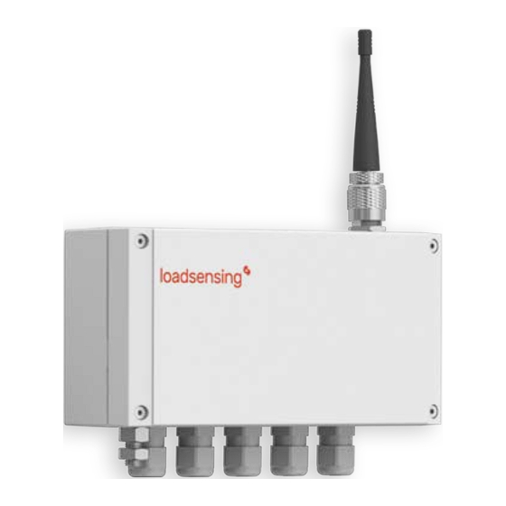
Page 6: Equipment Provided
Equipment provided The Loadsensing nodes are shipped with the following accessories: ● Vibrating wire data logger. ● Antenna. ● Antenna adapter. The package does not include: ● A USB-OTG configuration cable. ● Batteries. ● A grounding connector. ● Mounting support . The vibrating wire logger comprises: 1. - Page 7 Data Logger Mounting All vibrating wire data loggers can be deployed as follows, depending on the application and the conditions of the site: ● On a wall, using a metallic (LS-MEC-MP-001) or polycarbonate (LS-ACC-MP-P) mounting support. ● On a 35-mm or 50-mm mounting pole, using an aluminum mounting plate (LS-ACC-POLE35-2/LS-ACC-POLE50-2).
-
Page 8: Sensor Connection
Sensor connection Most vibrating wire sensors can be connected to the Loadsensing vibrating wire data loggers. Further information can be found in the vibrating logger specification chapter. The data logger has a cable gland for each channel, to allow you to adjust di erent sensor cable diameters. -
Page 9: Powering The Wireless Data Logger
Powering the wireless data logger The Loadsensing vibrating wire nodes are shipped closed, without batteries. To power it up, follow these steps: 1. Open the vibrating wire node using a 2.5 mm Allen key. 2. A small RTC battery was shipped inside the ½ AA size battery holder in our multichannel data loggers in order to keep time regar dl ess of whether C-type batteries are also inserted in the data logger. - Page 10 4. Insert C-type batteries in the battery holders. The single channel node takes only one battery and the multichannel node has up to four (more batteries will give the logger a longer life for a given configuration). See our LS G6 data logger recommended batteries guide for further information.
-
Page 11: Loadsensing Device Configuration
Device Configuration We strongly recommend configuring the device on location so you can conduct an on-site radio coverage test at the same time. Device configuration has to be carried out using the Worldsensing Android app (WS App), which i s compatible with USB On-The-Go (OTG) Android devices. Please refer to the Worldsensing app User Guide for more details. - Page 12 There are some configurations and functionalities that are particular for the vibrating wire node, such as configuring the sweep frequency from the sensor and setting a specific magnitude threshold to detect if the sensor has been disconnected. User will need to add the channels that want to read, with a suitable sweep frequency group from the sensor.
- Page 13 A sweep custom frequency is also available on the app, where a custom start and end frequency in Hz can be added and also a custom time (in ms) for reading the sensor. Fig.2 Sweep custom configuration. We recommend checking this information with the datasheet from the sensor manufacturer.
- Page 14 Algorithm refinement From Vibrating wire Data logger firmware version 2.43, the algorithm we use is able to improve resolution and accuracy using proper sweep configurations. Excitation Freqs. Accuracy - Error % Resolution Hz Sweep A 450-1125 0.013 0.002 Sweep B 800-2000 0.008 0.002...
- Page 15 Firmware readings comparison A comparison of strain gauge readings using the previous firmware and version 2.43 Version 2.43 also includes an advanced configuration option and users can use it to configure a magnitude threshold (see ‘Sensor detection functionality’ overleaf for more details) to avoid recording noise or induced frequencies on the cable.
- Page 16 Fig.3 Magnitude threshold configuration.
- Page 17 Sensor Detection Functionality Vibrating wire sensors may sometimes get disconnected due to a cut cable or other issues. This can lead to data analysis challenges when you are analyzing data remotely, as it could be interpreted as a node or a sensor failure, among other things. To reduce noise or induced frequencies, we’ve implemented a configurable threshold.
- Page 18 ● The noise level magnitude is usually under 0.01. When dealing with false errors, do the following in order: Make sure the node threshold is the default one. 2. Make sure the sweep you have configured covers the range of the sensor. 3.
- Page 19 Barometric Measurements As the data logger includes a barometer. It is important to avoid placing the data logger inside any type of container. This would a ect the readings the barometer makes through the gore valve. If the vibrating wire sensor requires barometric pressure compensation (such as for piezometers installed in locations that may be a ected by changes in barometric pressure), the current pressure readings from the barometer are usually used directly.
-
Page 20: Safely Closing The Vibrating Wire Logger
Safely Closing the Vibrating Wire Logger This is important to ensure water tightness and the durability of the node. Close the cover by cross-screwing the 2.5 Nm/2Nm torque as indicated. Please see the Watertightness document for detailed information. The Loadsensing vibrating wire data loggers have undergone water tightness testing by an external laboratory and are rated at IPX7 (one meter for 30 minutes). - Page 21 properly sealed and the degree of protection against water intrusion could be compromised. ● You screw the box at 2,5 Nm/2 Nm (depending on the vibrating wire data logger model-the force that needs to be applied is marked on the outside of the device-) using a torque screwdriver (e.g.
-
Page 22: Node Surge Protection
Node Surge Protection Following IEC 61000-4-5, vibrating wire data loggers have been equipped with class 2 surge immunity protection against damaging spikes and transients. That means the node is protected up to 1kV. You need to ground the node (metallic case nodes come with an easy-to-use grounding screw), otherwise the surge protection cannot prevent the node from being damaged by direct or indirect lightning. - Page 23 Figure 8: Available formulae for engineering units conversion on Vibrating wire logger. Please note that vibrating wire readings can be used on the formula in Hz or Digits and must be selected from the “Vw readings” drop-down menu. Formulae that can be used on the CMT menu are: Polynomial A Where A, B and C are polynomial gage factors, K is thermal factor and D is an o set in units...
- Page 24 Where C ’s are polynomial gage factors and D is an o set in units Linear A Where G is the linear factor , K is the thermal factor and D is an o set in units Linear B Where G is the linear factor , K is the thermal factor and D is an o set in units Linear A with compensation Where G is the linear factor , K is the thermal factor, F is a conversion factor for pressure and D is an o set in units...
- Page 25 Linear B with compensation Where G is the linear factor , K is the thermal factor, F is a conversion factor for pressure and D is an o set in units Polynomial A with compensation Where A, B and C are polynomial gage factors, K is thermal factor, F is a conversion factor for pressure and D is an o set in units...
- Page 26 Polynomial B with compensation Where C ’s are polynomial gage factors, F is a conversion factor for pressure and D is an o set in units Third degree polynomial with compensation Where A, B, C and D are polynomial gage factors, K is the thermal factor, F is a conversion factor for pressure and E is an o set in units It is not possible to convert data to more than one engineering unit (i.e piezometer reading can be converted to pressure or to meters, but not both).
- Page 27 VW load cells (3 gauges averaged channels 1, 2, 3) Where B is a calibration factor and D is an o set in units VW load cells (5 gauges averaged) Where B is a calibration factor and D is an o set in units On the bottom of the page, formulae for thermistor conversion can be selected.
- Page 28 On the pressure gear, it is possible to convert measured pressure with the internal barometer from the Vibrating wire datalogger and convert it to pressure at sea level. This pressure will be used for barometric compensation formulae. Figure 10: Formula for converting pressure...
-
Page 29: Maintenance And Troubleshooting
Errors implemented When a missing sensor is detected, an error is returned and a timestamp is registered on the reading error CSV file on the CMT , while the reading file will show blank readings corresponding to that timestamp. Please note that this feature is available for CMT with firmware version 2.4.1 onwards. Maintenance and troubleshooting The node is packaged in a rugged aluminum box and should provide many years of trouble-free operation. -
Page 30: Battery Lifespan
Worldsensing is not liable for damages or erroneous decisions caused by defective units, since it is only responsible for the warranty of the equipment. Battery Lifespan Battery consumption varies depending on the number of sensors, sampling rate and environmental and wireless network conditions. The following tables provide the battery lifespan in years per channel according to di erent wireless network conditions. -
Page 31: Data Storage
Table 3: Battery lifespan in years per vibrating wire node channel assuming extreme environmental conditions for European radios. Number Sampling rate Sampling rate (considering SF 7 14dB) (considering SF 11 14dB) channels 30 secs 30 min 30 secs 5 min 30 min 0.03 7.21... - Page 32 Data is stored in comma-separated value (CSV) files. You can download readings and health files using the WS App. To do this, connect an Android device to the node Mini USB port with a USB-OTG cable. When WS App loads, download data by clicking on the Download Data tab. You need to set a start and end date for the data you want to download.
-
Page 33: Faqs
FAQs How can I improve the resolution of the vibrating wire data logger? We’ve improved the resolution and accuracy from data logger firmware version 2.43. and gateway firmware version 2.4.1 onwards. To benefit from this feature, make sure you use a sweep frequency group instead of configuring a custom sweep frequency within a wider frequency range. - Page 34 Check the wires. You can do this with the sensor wired detection function, although it is important to set the correct threshold on the node. If the variation is not due to any of these causes, it is possible that the sensor or the data logger has burnt out due to an electrical discharge.
- Page 35 Should I expect the same radio coverage while using the LS-G6-VW-1P? You can expect lower radio coverage with the polycarbonate case node, as it comes with an internal antenna. As a rule of thumb the internal antenna has 60-70% of the range of the external one.
-
Page 36: Contact Worldsensing
CONTACT WORLDSENSING Need more support? Get in touch with our Customer Success team: Email: industrialsupport@worldsensing.com Phone: +34 93 418 05 85 (08.30h - 16.30h UTC) Want to stay up-to-date about Worldsensing? Sign up for our newsletter: www.worldsensing.com Visit our blog for interesting content: blog.worldsensing.com Download the latest datasheets and infographics: www.worldsensing.com/download-center...
Need help?
Do you have a question about the LS-G6-VW and is the answer not in the manual?
Questions and answers