Table of Contents
Advertisement
Advertisement
Table of Contents

Related Manuals for Asus P8B WS


Summary of Contents for Asus P8B WS
- Page 1 P8B WS...
- Page 2 Product warranty or service will not be extended if: (1) the product is repaired, modified or altered, unless such repair, modification of alteration is authorized in writing by ASUS; or (2) the serial number of the product is defaced or missing.
-
Page 3: Table Of Contents
Contents Notices ... vi Safety information ... viii About this guide ... ix P8B WS specifications summary ... xi Chapter 1: Product introduction Welcome! ... 1-1 Package contents ... 1-1 Special features ... 1-2 1.3.1 Product highlights ... 1-2 1.3.2 ASUS Workstation Exclusive Features ... - Page 4 Asus SPD Information ... 3-30 Exit menu ... 3-31 3.10 Updating BIOS ... 3-32 3.10.1 ASUS Update utility ... 3-33 3.10.2 ASUS EZ Flash Utility ... 3-36 3.10.3 ASUS CrashFree BIOS 3 utility ... 3-37 3.10.4 ASUS BIOS Updater ... 3-38 BIOS setup...
- Page 5 Contents Chapter 4: Software support Installing an operating system ... 4-1 Support DVD information ... 4-1 4.2.1 Running the support DVD ... 4-1 4.2.2 Obtaining the software manuals ... 4-2 Software information ... 4-3 4.3.1 AI Suite II ... 4-3 4.3.2 EPU ...
-
Page 6: Notices
Notices Federal Communications Commission Statement This device complies with Part 15 of the FCC Rules. Operation is subject to the following two conditions: • This device may not cause harmful interference, and • This device must accept any interference received including interference that may cause undesired operation. - Page 7 REACH.htm. ASUS Recycling/Takeback Services ASUS recycling and takeback programs come from our commitment to the highest standards for protecting our environment. We believe in providing solutions for you to be able to responsibly recycle our products, batteries, other components as well as the packaging materials.
-
Page 8: Safety Information
Safety information Electrical safety • To prevent electrical shock hazard, disconnect the power cable from the electrical outlet before relocating the system. • When adding or removing devices to or from the system, ensure that the power cables for the devices are unplugged before the signal cables are connected. If possible, disconnect all power cables from the existing system before you add a device. -
Page 9: About This Guide
Refer to the following sources for additional information and for product and software updates. ASUS websites The ASUS website provides updated information on ASUS hardware and software products. Refer to the ASUS contact information. Optional documentation Your product package may include optional documentation, such as warranty flyers, that may have been added by your dealer. -
Page 10: Conventions Used In This Guide
Conventions used in this guide To ensure that you perform certain tasks properly, take note of the following symbols used throughout this manual. DANGER/WARNING: Information to prevent injury to yourself when trying to complete a task. CAUTION: Information to prevent damage to the components when trying to complete a task. -
Page 11: P8B Ws Specifications Summary
® workstation processor Supports 32nm CPU * Supports Intel Turbo Boost Technology 2.0 ® ** Refer to www.asus.com for Intel CPU support list Intel C206 Chipset ® 4 x DIMM, max. 32GB, DDR3 1333/1066 MHz, ECC/non-ECC, un-buffered memory Dual channel architecture Support Intel Extreme Memory Profile (XMP) **Refer to www.asus.com or this user manual for the... - Page 12 ASUS SASsaby series Cards support ASUS WS Diag. LED 32 Mb Flash ROM, EFI AMI BIOS, PnP, DMI2.0, WfM2.0, SM BIOS 2.6, ACPI 2.0a, Multi-language BIOS, ASUS EZ Flash Utility, ASUS CrashFree BIOS 3 PS/2 KB/MS port S/PDIF Out (Optical and Coxial) 6 x USB 2.0/1.1 ports...
- Page 13 P8B WS specifications summary Internal I/O Connectors Manageability Form Factor *Specifications are subject to change without notice. 24-pin ATX Power connector 8-pin ATX +12V Power connector CPU fan with PWM control Chassis fan1 with Q-fan control Chassis fan2 with Q-fan control...
-
Page 15: Chapter 1: Product Introduction
This chapter describes the motherboard features and the new technologies it supports. Chapter 1: Product introduction... - Page 16 Chapter summary Welcome! ... 1-1 Package contents ... 1-1 Special features ... 1-2 ASUS P8B WS...
-
Page 17: Welcome
Welcome! Thank you for buying an ASUS P8B WS motherboard! The motherboard delivers a host of new features and latest technologies, making it another standout in the long line of ASUS quality motherboards! Before you start installing the motherboard, and hardware devices on it, check the items in your package with the list below. -
Page 18: Special Features
Green ASUS This motherboard and its packaging comply with the European Union’s Restriction on the use of Hazardous Substances (RoHS). This is in line with the ASUS vision of creating environment-friendly and recyclable products/packagings to safeguard consumers’ health while minimizing the impact on the environment. -
Page 19: Asus Workstation Exclusive Features
Core i3 2nd generation desktop processors. Users can choose DDR3 un-buffered non-ECC memory which is widely available in the PC market, or more stable and reliable DDR3 un-buffered ECC memory. P8B WS provide you flexible options on CPU and memory to meet diverse needs. -
Page 20: Asus Features
Personal Supercomputer when working in tangent with discrete CUDA technology—providing unprecedented return on investment. Users can count on up to 4 Tesla GPUs that are plugged into P8B WS for intensive parallel computing on tons of data, which delivers nearly 4 teraflops of performance. It is the best choice to work as a personal supercomputer on your desk instead of a computer cluster in a room. -
Page 21: Asus Quiet Thermal Solution
Fan Xpert Active Quiet & Cool ASUS Fan Xpert intelligently allows users to adjust both the CPU and chassis fan speed according to different ambient temperature, which is caused by different climate conditions in different geographic regions and system loading. - Page 22 BIOS only in a few clicks without preparing an additional floppy diskette or using an OS-based flash utility. ASUS CrashFree BIOS 3 The ASUS CrashFree BIOS 3 allows users to restore corrupted BIOS data from a USB flash disk containing the BIOS file. Precision Tweaker 2 Allows you to fine-tune the CPU voltage in 0.01V steps and DRAM voltage in...
-
Page 23: Asus Crystal Sound
ASUS Crystal Sound 8 Channel Audio Codec The onboard 8-channel HD audio (High Definition Audio, previously codenamed Azalia) CODEC enables high-quality Absolute Pitch 192khz/24bit audio output, true BD lossless sound, jack-sensing feature, retasking functions and multi-streaming technology. ASUS P8B WS... - Page 24 Chapter 1: Product Introduction...
-
Page 25: Chapter 2: Hardware Information
This chapter lists the hardware setup procedures that you have to perform when installing system components. It includes description of the jumpers and Chapter 2: Hardware connectors on the motherboard. information... - Page 26 Chapter summary Before you proceed ... 2-1 Motherboard overview ... 2-2 Building your computer system ... 2-30 Starting up for the first time ... 2-46 Turning off the computer ... 2-47 ASUS P8B WS...
-
Page 27: Before You Proceed
Before you install or remove any component, ensure that the ATX power supply is switched off or the power cord is detached from the power supply. Failure to do so may cause severe damage to the motherboard, peripherals, or components. ASUS P8B WS... -
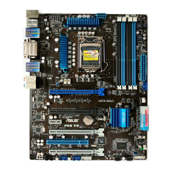
Page 28: Motherboard Overview
Motherboard overview 2.2.1 Motherboard layout Refer to 2.8 Connectors for more information about rear panel connectors and internal connectors. Chapter 2: Hardware information... -
Page 29: Layout Contents
Serial port connector (10-1 pin COM1) Digital audio connector (4-1 pin SPDIF_OUT) IEEE 1394a port connector (10-1 pin IE1394_2) Chassis Fan control setting (3-pin CHAFAN_SEL) Front panel audio connector (10-1 pin AAFP) ASUS P8B WS Page 2-28 2-24 2-13 2-14... -
Page 30: Central Processing Unit (Cpu)
ASUS will shoulder the cost of repair only if the damage is shipment/transit-related. • Keep the cap after installing the motherboard. ASUS will process Return Merchandise Authorization (RMA) requests only if the motherboard comes with the cap on the LGA1155 socket. -
Page 31: System Memory
The motherboard comes with four Double Data Rate 3 (DDR3) Dual Inline Memory Modules (DIMM) slots. A DDR3 module is notched differently from a DDR or DDR2 module. DO NOT install a DDR or DDR2 memory module to the DDR3 slot. Recommended memory configurations ASUS P8B WS... -
Page 32: Memory Configurations
CPU. • The max. 32GB memory capacity can be supported with DIMMs of 8GB (or above). ASUS will update QVL once the DIMMs are available on the market. • Always install DIMMs with the same CAS latency. For optimum compatibility, we recommend that you obtain memory modules from the same vendor. - Page 33 P8B WS Motherboard Qualified Vendors Lists (QVL) DDR������M��� capability Vendors Part No. Apacer 78.01GC6.9L0 Apacer 78.A1GC6.9L1 CORSAIR CMX8GX3M4A1333C9 Crucial CT12864BA1339.8FF Crucial BL25664BN1337.16FF(XMP) Crucial CT25664BA1339.16FF Crucial CT25672BA1339.18FF ELPIDA EBJ10UE8BDF0-DJ-F ELPIDA EBJ10UE8EDF0-DJ-F ELPIDA EBJ21UE8BDF0-DJ-F G.SKILL F3-10600CL9D-4GBNT G.SKILL F3-10666CL8D-4GBHK(XMP) G.SKILL F3-10666CL7D-4GBPI(XMP) G.SKILL F3-10666CL7D-4GBRH(XMP) G.SKILL...
-
Page 34: Memory Configuration
OCZ3RPR13332GK OCZ3G1333LV3GK SAMSUNG M378B5273BH1-CH9 SAMSUNG M378B5273CH0-CH9 SAMSUNG M378B5273DH0-CH9 ACTICA ACT1GHU64B8F1333S ACTICA ACT1GHU72C8G1333S ACTICA ACT2GHU64B8G1333M ACTICA ACT2GHU64B8G1333S ACTICA ACT2GHU72D8G1333M ACTICA ACT2GHU72D8G1333S ACTICA ACT4GHU64B8H1333H ACTICA ACT4GHU72D8H1333H BUFFALO FSH1333D3G-T3G(XMP) EK Memory EKM324L28BP8-I13 • 1 DIMM: Supports one module inserted in any slot as Single-channel memory configuration. - Page 35 P8B WS Motherboard Qualified Vendors Lists (QVL) DDR������M��� capability Vendors Part No. Size Crucial CT12864BA1067.8FF Crucial CT12864BA1067.8SFD Crucial CT12872BA1067.9FF Crucial CT25664BA1067.16FF Crucial CT25664BA1067.16SFD Crucial CT25672BA1067.18FF ELPIDA EBJ10UE8BAW0-AE-E ELPIDA EBJ10UE8EDF0-AE-F ELPIDA EBJ11UD8BAFA-AG-E ELPIDA EBJ21UE8BAW0-AE-E ELPIDA EBJ21UE8EDF0-AE-F GEIL GG34GB1066C8DC 4GB ( 2x...
-
Page 36: Expansion Slots
2.2.5 Expansion slots Ensure to unplug the power cord before adding or removing expansion cards. Failure to do so may cause you physical injury and damage motherboard components. Slot No. Slot Description PCIe 2.0 x16_1 slot (single at x16 or dual at x8/x8 mode) PCIe 2.0 x16_2 slot (x8 mode) PCIe 2.0 x1_1 slot PCIe 2.0 x16_3 slot (x4 mode) -
Page 37: Standard Interrupt Assignments
VIA1394 Asmedia USB3.0 LAN1 (82574) LAN2 (82574) SATA Controller 1 SATA Controller 2 USB 2.0 Controller 1 USB 2.0 Controller 2 HD Audio I.G.D. DT shared ASUS P8B WS – – – shared – – – – shared – –... -
Page 38: Onboard Switches
2.2.6 Onboard switches Onboard switches allow you to fine-tune performance when working on a bare or open-case system. This is ideal for overclockers and gamers who continually change settings to enhance system performance. EPU switch Turning this switch to Enable will automatically detect the current PC loadings and intelligently moderate the power consumption. - Page 39 GPU speed. For ensuring the system performance, turn the switch setting to Enable when the system is powered off. The GPU Boost Switch functions only when you install the DESKTOP CPU that supports onboard graphics. ASUS P8B WS 2-13...
- Page 40 DRAM_LED lights continuously. Replace the DIMMs with ones recommended in the Memory QVL (Qualified Vendors Lists) in this user manual or on the ASUS website at www.asus.com. • If you turn off the computer and replace DIMMs during the tuning process, the system continues memory tuning after turning on the computer.
-
Page 41: Onboard Leds
LED next to the error device will continue lighting until the problem is solved. This user-friendly design provides an intuitive way to locate the root problem within seconds. GPU Boost LED The GPU Boost LED lights when the GPU Boost switch is turned to Enable. ASUS P8B WS 2-15... - Page 42 EPU LED The EPU LED lights when the EPU switch is turned to Enable. Standby power LED The motherboard comes with a standby power LED that lights up to indicate that the system is ON, in sleep mode, or in soft-off mode. This is a reminder that you should shut down the system and unplug the power cable before removing or plugging in any motherboard component.
- Page 43 DRAM LED The DRAM_LED lights when the installed DIMMs incompatible with the motherboard or improperly installed. When using the MemOK! switch for automatic memory compatibility tuning, the DRAM_LED will blink. ASUS P8B WS 2-17...
-
Page 44: Jumper
2.2.8 Jumper Clear RTC RAM (3-pin CLRTC) This jumper allows you to clear the Real Time Clock (RTC) RAM in CMOS. You can clear the CMOS memory of date, time, and system setup parameters by erasing the CMOS RTC RAM data. The onboard button cell battery powers the RAM data in CMOS, which include system setup information such as system passwords. - Page 45 If you use a 4-pin fan but set the jumper to pin 1-2, the fan you installed may not work. • If you use a 3-pin fan but set the jumper for a 4-pin fan, the fan control will not work and the fan you installed will always run at full speed. ASUS P8B WS 2-19...
-
Page 46: Internal Connectors
2.2.9 Internal connectors Intel C206 Serial ATA 6.0 Gb/s connectors (7-pin SATA6G_1/2 [gray]) ® These connectors connect to Serial ATA 6.0 Gb/s hard disk drives via Serial ATA 6.0 Gb/s signal cables. • These connectors are set to [IDE Mode] by default. If you intend to create a Serial ATA RAID set using these connectors, set the SATA Mode item in the BIOS to [RAID Mode]. - Page 47 You must install Windows Serial ATA hard disk drives. The Serial ATA RAID feature is available only if you are using Windows ASUS P8B WS Rapid Storage Technology through the ® XP Service Pack 3 or later versions before using ®...
-
Page 48: Usb Connectors
Never connect a 1394 cable to the USB connectors. Doing so will damage the motherboard! You can connect the front panel USB cable to the ASUS Q-Connector (USB, blue) first, and then install the Q-Connector (USB) to the USB connector onboard if your chassis supports front panel USB ports. - Page 49 This connector is for an additional Sony/Philips Digital Interface (S/PDIF) port(s). Connect the S/PDIF Out module cable to this connector, then install the module to a slot opening at the back of the system chassis. The S/PDIF module is purchased separately. ASUS P8B WS 2-23...
- Page 50 CPU, chassis, and power fan connectors (4-pin CPU_FAN; 4-pin CHA_FAN1/2/3; 3-pin PWR_FAN) Connect the fan cables to the fan connectors on the motherboard, ensuring that the black wire of each cable matches the ground pin of the connector. Do not forget to connect the fan cables to the fan connectors. Insufficient air flow inside the system may damage the motherboard components.
- Page 51 This connector is for a serial (COM) port. Connect the serial port module cable to this connector, then install the module to a slot opening at the back of the system chassis. The COM module is purchased separately. ASUS P8B WS 2-25...
- Page 52 TPM connector (20-1 pin TPM) This connector supports a Trusted Platform Module (TPM) system, which can securely store keys, digital certificates, passwords, and data. A TPM system also helps enhance network security, protects digital identities, and ensures platform integrity. This connector can also serve for G.P. Diagnosis card installtion.
- Page 53 Wake up AP Detect PS2 mouse/keyboard Initiate VGA BIOS 9A-9D USB initiation Detect IDE Initiate option ROM ASUS P8B WS OS in PIC mode OS in APIC mode Leave BIOS and pass control to OS Resume from S1 Resume from S3...
-
Page 54: Atx Power Connectors
• If you are uncertain about the minimum power supply requirement for your system, refer to the Recommended Power Supply Wattage Calculator at http://support.asus.com/PowerSupplyCalculator/PSCalculator. aspx?SLanguage=en-us for details. • If you want to use two or more high-end PCI Express x16 cards, use a PSU with 1000W power or above to ensure the system stability. -
Page 55: System Panel Connector
BIOS settings. Pressing the power switch for more than four seconds while the system is ON turns the system OFF. • Reset button (2-pin RESET) This 2-pin connector is for the chassis-mounted reset button for system reboot without turning off the system power. ASUS P8B WS 2-29... -
Page 56: Building Your Computer System
Building your computer system 2.3.1 Additional tools and components to build a PC system 1 bag of screws PC chassis Intel LGA 1155 CPU DIMM SATA optical disc drive (optional) The tools and components in the table above are not included in the motherboard package. -
Page 57: Cpu Installation
2.3.2 CPU installation ASUS P8B WS 2-31... - Page 58 2-32 Chapter 2: Hardware information...
-
Page 59: Cpu Heatsink And Fan Assembly Installation
2.3.3 CPU heatsink and fan assembly installation To install the CPU heatsink and fan assembly ASUS P8B WS Apply the Thermal Interface Material to the CPU heatsink and CPU before you install the heatsink and fan if necessary. 2-33... - Page 60 To uninstall the CPU heatsink and fan assembly 2-34 Chapter 2: Hardware information...
-
Page 61: Dimm Installation
2.3.4 DIMM installation To remove a DIMM ASUS P8B WS 2-35... -
Page 62: Motherboard Installation
2.3.5 Motherboard installation The diagrams in this section are for reference only. The motherboard layout may vary with models, but the installation steps remain the same. 2-36 Chapter 2: Hardware information... - Page 63 DO NOT overtighten the screws! Doing so can damage the motherboard. ASUS P8B WS 2-37...
-
Page 64: Atx Power Connection
2.3.6 ATX Power connection 2-38 Chapter 2: Hardware information... -
Page 65: Sata Device Connection
2.3.7 SATA device connection ASUS P8B WS 2-39... -
Page 66: Front I/O Connector
2.3.8 Front I/O Connector To install ASUS Q-Connector To install USB Connector The actual location may vary with motherboards. 2-40 To install front panel audio connector AAFP Chapter 2: Hardware information... -
Page 67: Expension Card Installation
2.3.9 Expension Card installation To install PCIe x16 cards To install PCIe x1 cards To install PCI cards ASUS P8B WS 2-41... -
Page 68: Rear Panel Connection
2.3.10 Rear panel connection Rear panel connectors 1. PS/2 mouse and keyboard port 2. IEEE 1394a port 3. LAN (RJ-45) port 2* 4. DVI port 5. LAN (RJ-45) port 1* 6. USB 2.0 ports 5 and 6 *and **: Refer to the tables on the next page for LAN port and audio port definitions. 2-42 7. -
Page 69: Audio I/O Connections
Rear Speaker Out Gray – – 2.3.11 Audio I/O connections Audio I/O ports Connect to Headphone and Mic ASUS P8B WS OS environment and after the USB 3.0 driver installation. ® Speed LED Status Description 10 Mbps connection ORANGE 100 Mbps connection... - Page 70 Connect to Stereo Speakers Connect to 2.1 channel Speakers Connect to 4.1 channel Speakers 2-44 Chapter 2: Hardware information...
- Page 71 Connect to 5.1 channel Speakers Connect to 7.1 channel Speakers ASUS P8B WS 2-45...
-
Page 72: Starting Up For The First Time
Starting up for the first time After making all the connections, replace the system case cover. Be sure that all switches are off. Connect the power cord to the power connector at the back of the system chassis. Connect the power cord to a power outlet that is equipped with a surge protector. -
Page 73: Turning Off The Computer
BIOS setting. Pressing the power switch for more than four seconds lets the system enter the soft-off mode regardless of the BIOS setting. Refer to section 3.7 Power Menu for details. ASUS P8B WS 2-47... - Page 74 2-48 Chapter 2: Hardware information...
-
Page 75: Chapter 3: Bios Setup
This chapter tells how to change the system settings through the BIOS Setup menus. Detailed descriptions of the BIOS parameters are also provided. BIOS setup... - Page 76 Main menu ... 3-5 Ai Tweaker menu Ai Tweaker menu menu ... 3-8 Advanced menu ... 3-13 Monitor menu ... 3-24 Boot menu ... 3-27 Tools menu ... 3-28 Exit menu ... 3-31 3.10 Updating BIOS ... 3-32 ASUS P8B WS...
-
Page 77: Knowing Bios
The BIOS setup program can be used under two modes: EZ Mode and Advanced Mode. You can change modes from the Exit menu or from the Exit/Advanced Mode button in the EZ Mode/Advanced Mode screen. ASUS P8B WS See section 2.2.7... -
Page 78: Ez Mode
Exits the BIOS setup program without saving the changes, saves the changes and resets the system, or enters the Advanced Mode P8B WS BIOS Version : 0301 CPU Type : Intel(R) Core(TM) i5-2300 CPU 0 @ 2.80GHz Total Memory : 1024 MB (DDR3 1066MHz) Voltage 1.248V... -
Page 79: Advanced Mode
The Advanced Mode provides advanced options for experienced end-users to configure the BIOS settings. The figure below shows an example of the Advanced Mode. Refer to the following sections for the detailed configurations. To access the EZ Mode, click Exit, then select ASUS EZ Mode. Menu Menu bar... -
Page 80: Menu Items
Menu items The highlighted item on the menu bar displays the specific items for that menu. For example, selecting Main shows the Main menu items. The other items (Ai Tweaker, Advanced, Monitor, Boot, Tool, and Exit) on the menu bar have their respective menu items. Back button This button appears when entering a submenu. -
Page 81: Main Menu
RTC RAM. The Administrator or User Password items on top of the screen show • the default Not Installed. After you set a password, these items show Installed. ASUS P8B WS Advanced Monitor 0301 x64 01/24/2011 7.0.2.1164... -
Page 82: Administrator Password
Administrator Password If you have set an administrator password, we recommend that you enter the administrator password for accessing the system. Otherwise, you might be able to see or change only selected fields in the BIOS setup program. To set an administrator password: Select the Administrator Password item and press <Enter>. -
Page 83: User Password
To clear the user password, follow the same steps as in changing a user password, but press <Enter> when prompted to create/confirm the password. After you clear the password, the User Password item on top of the screen shows Not Installed. ASUS P8B WS... -
Page 84: Ai Tweaker Menu
Ai Tweaker menu The Ai Tweaker menu items allow you to configure overclocking-related items. Be cautious when changing the settings of the Ai Tweaker menu items. Incorrect field values can cause the system to malfunction. The configuration options for this section vary depending on the CPU and DIMM model you installed on the motherboard. - Page 85 This item appears only when you set the EPU Power Saving Mode item to [Enabled.] and allows you to select the EPU power saving mode. Configuration options: [AUTO] [Light Power Saving Mode] [Medium Power Saving Mode] [Max Power Saving Mode] ASUS P8B WS use the <+> and <-> keys to...
-
Page 86: Gpu Boost
GPU Boost GPU Boost accelerates the integrated GPU for extreme graphics performance. Configuration options: [Ok] [Cancel] DRAM Timing Control The sub-items in this menu allow you to set the DRAM timing control features. Use the <+> and <-> keys to adjust the value. To restore the default setting, type [auto] using the keyboard and press the <Enter>... -
Page 87: Cpu Offset Mode Sign
CPU permanently. We recommend you install the DIMMs with the voltage requirement below 1.5V. VCCIO Voltage [Auto] Allows you to set the VCCIO voltage. The values range from 0.90V to 1.70V with a 0.01V interval. ASUS P8B WS 3-11... - Page 88 VCCSA Voltage [Auto] Allows you to set the VCCSA voltage. The values range from 0.77V to 1.60V with a 0.01V interval. CPU PLL Voltage [Auto] Allows you to set the CPU PLL voltage. The values range from 1.20V to 2.20V with a 0.01V interval.
-
Page 89: Advanced Menu
EFI BIOS Utility - Advanced Mode Ai Tweaker Main Back Advanced\ Trusted Computing > TPM Configuration TPM SUPPORT This item appears only when you install TPM module to the motherboard. ASUS P8B WS Advanced Monitor Advanced Monitor Disabled Exit Boot Tool CPU Configuration Parameters →←: Select Screen... -
Page 90: Cpu Configuration
�.5.2 CPU Configuration The items in this menu show the CPU-related information that the BIOS automatically detects. The items shown in this screen may be different due to the CPU you installed. EFI BIOS Utility - Advanced Mode Ai Tweaker Main Back Advanced\... - Page 91 CPU C3 Report [Enabled] Allows you to disable or enable the CPU C3 report to OS. CPU C6 Report [Enabled] Allows you to disable or enable the CPU C6 report to OS. ASUS P8B WS SpeedStep Technology ® Turbo Mode ®...
-
Page 92: System Agent Configuration
�.5.� System Agent Configuration EFI BIOS Utility - Advanced Mode Ai Tweaker Main Back Advanced\ System Agent Configuration > System Agent Configuration Initiate Graphic Adapter iGPU Memory Render Standby iGPU Multi-Monitor Initiate Graphic Adapter [PEG/PCI] Allows you to select the desired graphics controller as the primary boot device. Configuration options: [iGPU] [PCI/iGPU] [PCI/PEG] [PEG/PCI] iGPU Memory [64M] Allows you to select the iGPU share memory size. -
Page 93: Pch Configuration
Serial-ATA Controller 0 Serial-ATA Controller 1 S.M.A.R.T. Status Check SATA6G_1 (Gray) SATA6G_2 (Gray) SATA3G_3 (Blue) SATA3G_4 (Blue) SATA3G_5 (Blue) SATA3G_6 (Blue) Version 2.00.1201. Copyright (C) 2011 American Megatrends, Inc. ASUS P8B WS Advanced Monitor Enabled Advanced Monitor IDE Mode Enhanced Enhanced Enabled... - Page 94 SATA Mode [IDE Mode] Allows you to set the SATA configuration. [Disabled] Disables the SATA function. [IDE Mode] Set to [IDE Mode] when you want to use the Serial ATA hard disk drives as Parallel ATA physical storage devices. [AHCI Mode] Set to [AHCI Mode] when you want the SATA hard disk drives to use the AHCI (Advanced Host Controller Interface).
-
Page 95: Usb Configuration
Enables the support for USB 3.0 devices on legacy operating systems (OS). EHCI Hand-off [Disabled] [Disabled] Disables the function. [Enabled] Enables the support for operating systems without an EHCI hand-off feature. ASUS P8B WS Advanced Monitor Enabled Enabled Disabled Exit Boot Tool Enables Legacy USB support. -
Page 96: Onboard Devices Configuration
�.5.7 Onboard Devices Configuration EFI BIOS Utility - Advanced Mode Main Ai Tweaker Back Advanced\ Onboard Devices Configuration > HD Audio Controller Front Panel Type SPDIF Out Type VIA 1394 Controller Intel LAN2 Controller Intel LAN2 OPROM Intel LAN1 Controller Intel LAN1 OPROM Asmedia USB 3.0 Controller Asmedia USB 3.0 Battery Charging Support... -
Page 97: Serial Port Configuration
Allows you to select the Serial Port base address. This item appears when Serial Port is set to [Enabled]. Configuration options: [IO=3F8h; IRQ=4] [IO=2F8h; IRQ=3] [IO=3E8h; IRQ=4] [IO=2E8h; IRQ=3] IO=3E8h; IRQ=4] [IO=2E8h; IRQ=3] ] [IO=2E8h; IRQ=3] IO=2E8h; IRQ=3] ] ASUS P8B WS IO=2F8h; IRQ=3] ] 3-21... -
Page 98: Apm
3.5.8 EFI BIOS Utility - Advanced Mode Main Ai Tweaker Back Advanced\ APM > Restore AC Power Loss Power On By PS/2 Keyboard Power On By PS/2 Mouse Power On By PCI Power On By PCIE Power On By Ring Power On By RTC Restore AC Power Loss [Power Off] [Power Off]... - Page 99 Power On By RTC [Disabled] [Disabled] Disables RTC to generate a wake event. When set to [Enabled], the items RTC Alarm Date (Days) and [Enabled] Hour/Minute/Second will become user-configurable with set values. ASUS P8B WS 3-23...
-
Page 100: Monitor Menu
Monitor menu The Monitor menu displays the system temperature/power status, and allows you to change the fan settings. EFI BIOS Utility - Advanced Mode Ai Tweaker Main CPU Temperature MB Temperature CPU Fan Speed Chassis Fan 1 Speed Chassis Fan 2 Speed Chassis Fan 3 Speed Power Fan Speed CPU Q-Fan Control... - Page 101 [Disabled] Disables the Chassis Q-Fan control feature. [Enabled] Enables the Chassis Q-Fan control feature. ASUS P8B WS The values range from 20ºC to minimum CPU fan duty cycle. The values When the CPU temperature is under 40ºC, the CPU fan 0ºC to...
- Page 102 Chassis Fan Speed Low Limit [600 RPM] This item appears only when you enable the Chassis Q-Fan Control feature and allows you to disable or set the chassis fan warning speed. Configuration options: [Ignore] [200 RPM] [300 RPM] [400 RPM] [500 RPM] [600 RPM] Chassis Fan Profile [Standard] This item appears only when you enable the Chassis Q-Fan Control feature...
-
Page 103: Boot Menu
Disables the full screen logo display feature. [Enabled] Enables the full screen logo display feature. Set this item to [Enabled] to use the ASUS MyLogo 2™ feature. Option ROM Messages [Force BIOS] [Force BIOS] The third-party ROM messages will be forced to display during the boot sequence. -
Page 104: Tool Menu
> ASUS O.C. Profile > ASUS SPD Information 3.8.1 ASUS EZ Flash Utility Allows you to run ASUS EZ Flash Utility. When you press <Enter> to start the application. For more details, refer to section 3.10.2 ASUS EZ Flash Utility. 3-28... -
Page 105: Asus O.c. Profile
This item allows you to store or load multiple BIOS settings. EFI BIOS Utility - Advanced Mode Ai Tweaker Main Back Tool\ ASUS O.C. Profile > O.C. Profile Configuration ========================================================== Setup Profile1 Status : Setup Profile2 Status : Setup Profile3 Status :... -
Page 106: Asus Spd Information
3.8.3 Asus SPD Information EFI BIOS Utility - Advanced Mode Main Ai Tweaker Back Tool\ Asus SPD Information > DIMM Slot # Manufacturer Module Size Maximum Bandwidth Part Number Serial Number Product Week/Year SPD Ext. JEDEC ID Frequency(Mhz) Voltage(V) CAS# Lantency(tCL) -
Page 107: Exit Menu
This option allows you to enter the EZ Mode screen. Launch EFI Shell from filesystem device This option allows you to attempt to launch the EFI Shell application (shellx64.efi) from one of the available filesystem devices. ASUS P8B WS 3-31... -
Page 108: Updating Bios
Carefully follow the instructions of this chapter to update your BIOS if necessary. Visit the ASUS website (www.asus.com) to download the latest BIOS file for this motherboard. The following utilities allow you to manage and update the motherboard BIOS setup program. -
Page 109: Asus Update Utility
3.10.1 ASUS Update utility The ASUS Update is a utility that allows you to manage, save, and update the motherboard BIOS in Windows • Update the BIOS directly from the Internet • Download the latest BIOS file from the Internet •... - Page 110 Select the ASUS FTP site nearest you to avoid network traffic. If you want to enable the BIOS downgradable function and auto BIOS backup function, check the checkboxs before the two items on the screen. Select the BIOS version that you want to download.
- Page 111 The screenshots in this section are for reference only. The actual BIOS information vary by models. • Refer to the software manual in the support DVD or visit the ASUS website at www.asus.com for detailed software configuration. ASUS P8B WS...
-
Page 112: Asus Ez Flash Utility
3.10.2 ASUS EZ Flash Utility The ASUS EZ Flash Utility feature allows you to update the BIOS without having to use a bootable floppy disk or an OS-based utility. Before you start using this utility, download the latest BIOS from the ASUS website at www.asus.com. -
Page 113: Asus Crashfree Bios 3 Utility
3.10.3 ASUS CrashFree BIOS 3 utility The ASUS CrashFree BIOS 3 utility is an auto recovery tool that allows you to restore the BIOS file when it fails or gets corrupted during the updating process. You can restore a corrupted BIOS file using the motherboard support DVD or a USB flash drive that contains the BIOS file. -
Page 114: Asus Bios Updater
3.10.4 ASUS BIOS Updater The ASUS BIOS Updater allows you to update BIOS in DOS environment. This utility also allows you to copy the current BIOS file that you can use as a backup when the BIOS fails or gets corrupted during the updating process. -
Page 115: Backing Up The Current Bios
The BIOS Updater backup screen appears indicating the BIOS backup process. When BIOS backup is done, press any key to return to the DOS prompt. ASUSTek BIOS Updater for DOS V1.18 [2011/04/29] Current ROM BOARD: P8B WS VER: 0301 DATE: 01/24/2011 PATH: A:\ BIOS backup is done! Press any key to continue. Note Saving BIOS: ASUS P8B WS Update ROM BOARD: Unknown VER: Unknown DATE: Unknown 3-39... -
Page 116: Updating The Bios File
Updating the BIOS file To update the BIOS file using BIOS Updater At the FreeDOS prompt, type bupdater /pc /g and press <Enter>. D:\>bupdater /pc /g The BIOS Updater screen appears as below. ASUSTek BIOS Updater for DOS V1.18 [2011/04/29] Current ROM BOARD: P8B WS VER: 0301 DATE: 01/24/2011 PATH: A:\ P8BWS.ROM 4194304 2011-01-24 17:30:48 Note [Enter] Select or Load [Tab] Switch [V] Drive Info [Up/Down/Home/End] Move [B] Backup [Esc] Exit Press <Tab> to switch between screen fields and use the <Up/Down/Home/ End>... -
Page 117: Chapter 4: Software Support
This chapter describes the contents of the support DVD that comes with the motherboard package and the software. Software support... - Page 118 Chapter summary Installing an operating system ... 4-1 Support DVD information ... 4-1 Software information ... 4-3 RAID configurations ... 4-11 Creating a RAID driver disk ... 4-16 ASUS P8B WS...
-
Page 119: Installing An Operating System
The contents of the support DVD are subject to change at any time without notice. Visit the ASUS website at www.asus.com for updates. 4.2.1 Running the support DVD Place the support DVD into the optical drive. -
Page 120: Obtaining The Software Manuals
The software manual files are in Portable Document Format (PDF). Install the Adobe Acrobat ® Click the Manual tab. Click ASUS Motherboard Utility Guide from the manual list on the left. The Manual folder of the support DVD appears. Double- click the folder of your selected software. -
Page 121: Software Information
4.3.1 AI Suite II AI Suite II is an all-in-one interface that integrates several ASUS utilities and allows users to launch and operate these utilities simultaneously. Installing AI Suite II To install AI Suite II on your computer Place the support DVD to the optical drive. -
Page 122: Epu
Select From the Last Reset to show the total CO2 that has been reduced *• since you click the Clear button • Refer to the software manual in the support DVD or visit the ASUS website at www.asus.com for detailed software configuration. Displays the following message if no VGA power saving engine is detected. -
Page 123: Fan Xpert
70°C. User: Allows you to configure the CPU fan profile under certain limitations. • Refer to the software manual in the support DVD or visit the ASUS website at www.asus.com for detailed software configuration. ASUS P8B WS Click to select a fan profile... -
Page 124: Probe Ii
Saves your configuration Loads your saved configuration Refer to the software manual in the support DVD or visit the ASUS website at www.asus.com for detailed software configuration. Applies your changes Loads the default threshold... -
Page 125: Sensor Recorder
Drag to view the status during a certain period of time Click to return to the default mode ASUS P8B WS Click to zoom in/out the Y axis Click to zoom in/out the X axis... -
Page 126: Ai Charger
4.3.6 Ai Charger+ Battery Charging Version 1.1 (BC 1.1), a USB Implementers Forum (USB-IF) certified USB charging function, is designed to make USB charging faster than the standard USB devices. If your USB device supports the BC 1.1 function*, when you connect your USB device to your system, the system automatically detects your USB device and starts a fast USB charging. -
Page 127: Audio Configurations
Double-click on the icon to display the Realtek HD Audio Manager. Realtek HD Audio Manager for Windows Configuration option tabs Control settings window ASUS P8B WS (Universal Audio Jack) technology for all audio ports, ® Audio Driver from the support ® Set default Minimize device button Realtek HD Audio Manager Vista™... - Page 128 Realtek HD Audio Manager for Windows XP Configuration options Control settings window Information button Refer to the software manual in the support DVD or visit the ASUS website at www.asus.com for detailed software configuration. 4-10 Exit button Minimize button Chapter 4: Software support...
-
Page 129: Raid Configurations
RAID 0 and RAID 1 configurations. Use four new hard disk drives or use an existing drive and three new drives for this setup. ASUS P8B WS XP Service Pack 3 or later versions before using ®... -
Page 130: Installing Serial Ata Hard Disks
4.4.2 Installing Serial ATA hard disks The motherboard supports Serial ATA hard disk drives. For optimal performance, install identical drives of the same model and capacity when creating a disk array. To install the SATA hard disks for a RAID configuration: Install the SATA hard disks into the drive bays. -
Page 131: Creating A Raid Set
When the Disks item is selected, press <Enter> to select the hard disk drives you want to include in the RAID set. The SELECT DISKS screen appears: Port Drive Model Serial # Size Status 0 ST3160812AS 9LS0HJA4 149.0GB Non-RAID Disk 1 ST3160812AS 9LS0F4HL 149.0GB Non-RAID Disk 2 ST3160812AS 3LS0JYL8 149.0GB Non-RAID Disk 3 ST3160812AS 9LS0BJ5H 149.0GB Non-RAID Disk Select 2 to 6 disks to use in creating the volume. [ ↑↓ ]-Prev/Next [SPACE]-SelectDisk [ENTER]-Done ASUS P8B WS [ CREATE VOLUME MENU ] Name: Volume0 RAID Level: RAID0(Stripe) Disks: Select Disks Strip Size: 128KB Capacity: 0.0 GB Sync: N/A Create Volume [ HELP ] 16 characters or less. - Page 132 Use the up/down arrow key to select a drive, and then press <Space> to select. A small triangle marks the selected drive. Press <Enter> after completing your selection. Use the up/down arrow key to select the stripe size for the RAID array (for RAID 0, 10 and 5 only),and then press <Enter>.
-
Page 133: Deleting A Raid Set
To exit the utility: From the utility main menu, select 5. Exit, and then press <Enter>. The following warning message appears: Are you sure you want to exit? (Y/N): Press <Y> to exit or press <N> to return to the utility main menu. ASUS P8B WS [ DELETE VOLUME MENU ] [ HELP ] [ CONFIRM EXIT ] 4-15... -
Page 134: Creating A Raid Driver Disk
Creating a RAID driver disk A floppy disk with the RAID driver is required when installing a Windows system on a hard disk drive that is included in a RAID set. The motherboard does not provide a floppy drive connector. You have •... -
Page 135: Installing The Raid Driver During Windows ® Os Installation
Follow the succeeding screen instructions to complete the installation. Before loading the RAID driver from a USB flash drive, you have to use another computer to copy the RAID driver from the support DVD to the USB flash drive. ASUS P8B WS ® Vista or later OS: ®... -
Page 136: Using A Usb Floppy Disk Drive
4.5.4 Using a USB floppy disk drive Due to OS limitation, Windows when you install the RAID driver from a floppy disk during the OS installation. To solve this issue, add the USB floppy disk drive’s Vendor ID (VID) and Product ID (PID) to the floppy disk containing the RAID driver. - Page 137 Type the following line to the bottom of the two sections: id = “USB\VID_xxxx&PID_xxxx”, “usbstor” [HardwareIds.scsi.iaAHCI_DesktopWorkstationServer] id= “PCI\VEN_8086&DEV_1C02&CC_0106”,”iaStor” id= “USB\VID_03EE&PID_6901”, “usbstor” [HardwareIds.scsi.iaStor_DesktopWorkstationServer] id= “PCI\VEN_8086&DEV_2822&CC_0104”,”iaStor” id= “USB\VID_03EE&PID_6901”, “usbstor” Add the same line to both sections. The VID and PID vary with different vendors. 10. Save and exit the file. ASUS P8B WS 4-19...
- Page 138 4-20 Chapter 4: Software support...
-
Page 139: Chapter 5: Multiple Gpu Technology Support
This chapter describes how to install and configure multiple ATI CrossFireX™ and ® NVIDIA SLI™ graphics cards. ® Multiple GPU technology support... -
Page 140: Chapter Summary
Chapter summary CrossFireX™ technology ... 5-1 ® NVIDIA CUDA™ technology ... 5-5 ® ASUS P8B WS... -
Page 141: Ati ® Crossfirex™ Technology
For Windows Vista, go to Control Panel > Programs and Features. Select your current graphics card driver/s. For Windows XP, select Add/Remove. For Windows Vista, select Uninstall. Turn off your computer. ASUS P8B WS CrossFireX™ technology that allows you to ®... -
Page 142: Installing Crossfirex Graphics Cards
5.1.3 Installing CrossFireX graphics cards The following pictures are for reference only. The graphics cards and the motherboard layout may vary with models, but the installation steps remain the same. Prepare two CrossFireX-ready graphics cards. Insert the two graphics card into the PCIEX16 slots. -
Page 143: Installing The Device Drivers
Cayalist Control Center. The Catalyst Control Center Setup Assistant appears when the system detects the existance of multi- graphics cards. Click Go to continue to the Catalyst Control Center Advanced View window. ASUS P8B WS CrossFireX™ technology ® desktop and ® ®... - Page 144 Enabling Dual CrossFireX settings In the Catalyst Control Center window, click Graphics Settings > CrossFireX > Configure. From the Graphics Adapter list, select the graphics card to act as the display GPU. Select Enable CrossFireX. Click Apply, and then click OK to exit the window.
-
Page 145: Nvidia ® Cuda™ Technology
PCIe x16_1, PCIe x16_2, PCIe x16_3, and PCIe x16_4 slot. Ensure that the cards are properly seated on the slot. ASUS P8B WS CUDA™ technology ® CUDA™ technology and up to 4 NVIDIA ® Windows XP/ Vista/ Linux RHEL5.X/ Open SuSE11.X OS... - Page 146 Connect either one 8-pin power connector or two 6-pin power connectors from the power supply to the Quadro graphics card and Tesla computing processor card(s). Connect a display cable to the graphics card. Refer to the documentation that came with your graphics card package to install the device drivers.
-
Page 147: Asus Contact Information
Telephone ASUS COMPUTER INTERNATIONAL (America) Address Web site Technical Support Telephone (General) Support fax Online support ASUS COMPUTER GmbH (Germany and Austria) Address Telephone Web site Online contact Technical Support Telephone Support Fax Online support 15 Li-Te Road, Peitou, Taipei, Taiwan 11259 +886-2-2894-3447 http://www.asus.com.tw...