Advertisement
Quick Links
All dimensions are approximate and subject to the limitations of the materials used and the methods of manufacture
Manufacturer:
Dunster House Ltd.
Caxton Road
Bedford
Bedfordshire
England
MK41 0LF
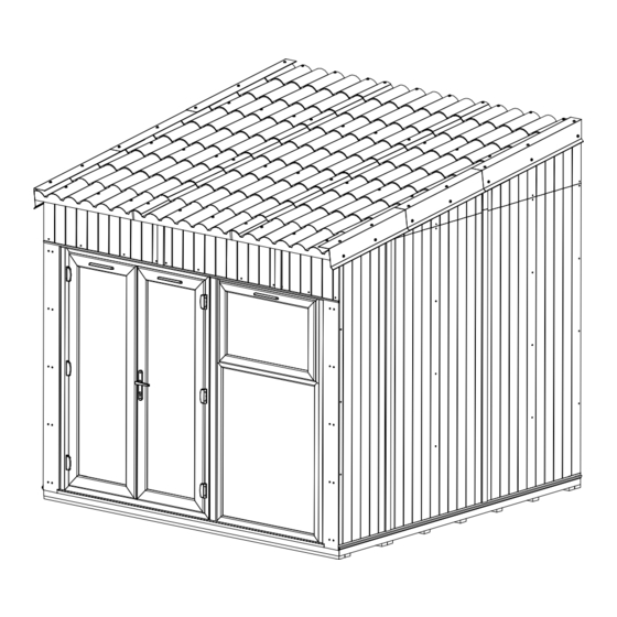
Addroom 3.0m x 3.0m
G3-3030GGR (Grooved)
G3-3030GGR-G (Grooved/Grey Windows)
INSTALLATION MANUAL
Please read this installation manual carefully
before proceeding with the construction of your Addroom.
Important!
Unique Reference Number
_____________________________
V3
Customer Service:
cs@dunsterhouse.co.uk
www.dunsterhouse.co.uk
Advertisement

Related Manuals for Dunster House Addroom G3-3030GGR


Summary of Contents for Dunster House Addroom G3-3030GGR
- Page 1 Please read this installation manual carefully before proceeding with the construction of your Addroom. Important! All dimensions are approximate and subject to the limitations of the materials used and the methods of manufacture Manufacturer: Dunster House Ltd. Caxton Road Bedford Unique Reference Number Bedfordshire...
- Page 2 In the unlikely event that you need to contact us, please do so in writing to: Email: cs@dunsterhouse.co.uk Post: FAO Customer Services, Dunster House Ltd - Factory 1, Caxton Road, Bedford, MK41 0LF Our Customer Services department is open 9:00 - 17:00, Monday to Friday. Please include your Sales Order number starting with SO or your postcode so we can locate your order.
- Page 3 Glazing Windows and Doors Sealed units are approximately 10mm smaller in length and width than the aperture. This difference in size will be packed using bridge packers (4mm), black shims (2mm), and green shims (1mm). Bridge packers must be used only against the frame, while shims are to be used only next to sealed units.
- Page 4 Glazing Windows and Doors 5. After packing the sealed units correctly, refit the beads in the same position as you removed them; start with the smallest lengths first before inserting the longer lengths. Carefully use a nylon or non-marking rubber mallet to help tap the beads into position, starting at the ends.
- Page 5 Variants Reinforced 70x70 post Reinforced 70x70 post Please note: This manual describes the assembly steps for the first variant. To assemble the second variant, please apply same assembly principles. Position of the reinforced 70x70 post is shown above. Page 5...
-
Page 6: Pack Contents
Pack Contents STEP 4 AND 6 STEP 4 AND 6 Right Left 2400 2400 Side ext. panel 1200x2400mm Side ext. panel 600x2400mm (1x right + 1x left) STEP 6 STEP 5 2905 2905 Apex ext. panel right 420x2905mm Apex ext. panel left 420x2905mm STEP 14 STEP 14 Apex ext. - Page 7 Pack Contents STEP 13 STEP 2 2735 3000 Lintel int. panel 385x2735mm Floor panel 1200x3000mm STEP 2 STEP 26 2025 3000 Floor panel 615x3000mm GR-WHITE WPC-2025x160x10.A STEP 10 AND 11 STEP 1 3015 GR-45x140x2730 - L = 2730mm GR-45x140x2795 - L = 2795mm 10x GR-35x70x3015 STEP 23 AND 27 STEP 3...
- Page 8 Pack Contents STEP 24 STEP 22 GR-GE-1200x370x10 Glass (with Bridge packers, Black + Green shims) STEP 20 STEP 19 1045 1480 Window 1045x1990mm (with uPVC glazing beads) Door 1480x1990mm (with uPVC glazing beads) STEP 19 AND 20 STEP 19 AND 20 1990 1990 25mm FRAME WIDENER...
- Page 9 Pack Contents STEP 29 AND 30 STEP 28 1015 1250 GR-FRONT FASCIA Ob-32 Flashing STEP 15 AND 16 STEP 15, 16, 29 AND 30 Roof panel 3150x1015mm (1x leading, 2x standard) 71x 19mm Grey screw cap (incl. extra) STEP 14, 25, 26, 31 AND 32 STEP 19 AND 20 71x Beige self-adhesive cap (incl.
- Page 10 Pack Contents Fixing Included 60mm Bolt 8x M6 Hex Head Bolt 60mm 70x 35mm Csk Screw 120x 70mm Csk Screw 8x M6 Nyloc nut 65x 90mm Csk Screw 16x M6 Washer 24x M10 Hex Head Bolt 100mm 100mm Bolt 14x 120mm Csk Screw 130x 60mm Drywall Screw 24x M10 Nut 25mm Hex Head Self Drill Screw...
- Page 11 Assembly Steps Pre-drill parts before fixing with screws or bolts STEP 1 Joining a double bearer 1a) Prepare a base to specification listed on page 2. Items: (Use 7 screws per joint) 10x GR-35x70x3015 (Bearer) 1b) Place the bearers on the base as is shown in the 90mm Csk Screw 21x 90mm Csk Screw diagram and join double bearers by using 90mm Csk...
- Page 12 Assembly Steps Pre-drill parts before fixing with screws or bolts STEP 3 3a) Place the L PROFILES flush with the edges of floor panels as is shown in Items: the diagram. Cut off a small a piece of L PROFILE in corners to make L L PROFILE 50x50 (0200PW) - 3000mm PROFILES flush with each other.
-
Page 13: Left Side View
Assembly Steps Pre-drill parts before fixing with screws or bolts STEP 5 5a) Secure the Apex ext. panel left 420x2905mm as is shown in the diagram Items: below. Pre-drill bolt holes by using 10mm drill bit. Make sure that WPC Apex ext. -
Page 14: Right Side View
Assembly Steps Pre-drill parts before fixing with screws or bolts STEP 6 6a) Assemble the right side wall with apex as is shown in the diagram below. Items: Pre-drill bolt holes by using 10mm drill bit. Make sure that WPC brick/groove Side ext. - Page 15 Assembly Steps Pre-drill parts before fixing with screws or bolts STEP 7 7a) Attach the right side internal panels as is shown in the diagram below. Use Items: 60mm Drywall Screws. Make sure that each screw is screwed to the timber frame. Side int.
- Page 16 Assembly Steps Pre-drill parts before fixing with screws or bolts STEP 8 8a) Attach the left side internal panels as is shown in the diagram below. Use Items: 60mm Drywall Screws. Make sure that each screw is screwed to the timber frame. Side int.
- Page 17 Assembly Steps Pre-drill parts before fixing with screws or bolts STEP 9 9a) Attach the purlin brackets as is shown in the diagram below. Use 5x 35mm Csk Items: Screw per purlin bracket. SMB094 - PURLIN BRACKET 20x 35mm Csk Screw 35mm Csk Screw 35mm Csk Screw 35mm Csk Screw...
- Page 18 Assembly Steps Pre-drill parts before fixing with screws or bolts STEP 11 11a) Attach GR-45x140x2730 to the existing structure as is shown in the diagram Items: below. Use suitable type and amount of wall fixings (not supplied), compatible with GR-45x140x2730 the material of the existing wall structure.
- Page 19 Assembly Steps Pre-drill parts before fixing with screws or bolts STEP 13 13a) Attach Lintel int. panel 385x2735mm to the Lintel frame 375x2735mm as is Items: shown in the diagram below. Use 60mm Deywall Screws. Lintel int. panel 385x2735mm 12x 60mm Drywall Screw Please note: Some lines have been Lintel int.
- Page 20 Assembly Steps Pre-drill parts before fixing with screws or bolts STEP 14 14a) Attach Apex ext. panel right 85x590mm and Apex ext. panel left 85x590mm Items: by using 2x 70mm Csk Screw per each panel as is shown in the diagram below. Apex ext.
- Page 21 Assembly Steps Pre-drill parts before fixing with screws or bolts STEP 15 15a) Place the first Roof panel 3150x1015mm (leading) on the purlins (flush Items: with existing structure and flush with side wall). Use 150mm Hex Head Self Roof panel 3150x1015mm (leading) Drill Screw with Saddle Washer and make sure that each screw is fixed to the 12x 150mm Hex Head Self Drill Screw timber underneath the panel.
- Page 22 Assembly Steps Pre-drill parts before fixing with screws or bolts STEP 17 17a) Use suitable Flashing (not supplied) for making watertight ridge connection Items: between Addroom and existing structure. Follow instruction of manufacturer. Flashing Clear ext. use sealant+caulking gun 17b) Use Clear exterior use sealant and caulking gun (not supplied) to make side wall connection to existing wall structure watertight.
- Page 23 Assembly Steps Pre-drill parts before fixing with screws or bolts STEP 19 19a) Position the 3mm Packers between side wall and 25mm Frame widener as shown in Items: the diagram 19a. Door 25mm Frme widener 19b) Fix the 25mm Frame widener to the side wall by using screws specified in the 40mm Frme widener diagram 19b.
- Page 24 Assembly Steps Pre-drill parts before fixing with screws or bolts STEP 20 20a) Position the 3mm Packers between side wall and 25mm Frame widener as shown in Items: the diagram 20a. Fix the 25mm Frame widener to the side wall by using 90mm Csk Window Screws.
-
Page 25: Inside View
Assembly Steps Pre-drill parts before fixing with screws or bolts STEP 21 21a) Make sure that the Window is completely vertical (use spirit level) and secure the Items: structure by using screws specified in the diagram below. Open the door and window 16x 90mm Csk Screw sashes to access the frames for fixing. - Page 26 Assembly Steps Pre-drill parts before fixing with screws or bolts STEP 23 23a) Position the components GR-DRIP TRAY (C038) - 3015mm and Items: GR-BE/GE-WPC-615x370x10 as is shown in the diagram below. The top edge of GR-DRIP TRAY (C038) - 3015mm component GR-BE/GE-WPC-615x370x10 needs to be flush with roof panel.
- Page 27 Assembly Steps Pre-drill parts before fixing with screws or bolts STEP 24 24a) Position the components GR-BE/GE-WPC-1200x370x10 as is shown in the Items: diagram below. The top edge of each component GR-BE/GE-WPC-1200x370x10 GR-GE-WPC-1200x370x10 needs to be flush with roof panel. 16x 35mm Csk Screw 24b) Attach the components GR-BE/GE-WPC-1200x370x10 to the timber frame by using 35mm Csk Screw (use 8 screws per component).
- Page 28 Assembly Steps Pre-drill parts before fixing with screws or bolts STEP 26 26a) Position the components GR-WHITE WPC-2025x160x10.A as is shown in the Items: diagram below. Cut out corner of each component GR-WHITE WPC-2025x160x10.A, GR-WHITE WPC-2025x160x10.A apply a sealant (not supplied) to the joints and attach each component GR-WHITE 20x 35mm Csk Screw WPC-2025x160x10.A by using 35mm Csk Screws.
-
Page 29: Assembly Steps
Assembly Steps Pre-drill parts before fixing with screws or bolts STEP 28 28a) Apply a bead of sealant and attach 3x GR-FRONT FASCIA as is shown in Items: the diagram below. Use 10mm Pan Head Self Tapping Screws. GR-FRONT FASCIA 10x 10mm Pan Head Self Tapping Screw 28b) Fill the gaps on the outside between the Front fascia and Roof panel. - Page 30 Assembly Steps Pre-drill parts before fixing with screws or bolts STEP 30 30a) Apply a bead of sealant (not supplied) and position 3x Ob-32 Flashing as Items: is shown in the diagram below. Make 3rd Ob-32 Flashing flush with existing Ob-32 Flashing structure by using a Tin Snips.
- Page 31 Assembly Steps Pre-drill parts before fixing with screws or bolts STEP 32 32a) Apply a bead of sealant (not supplied) to the joints in the panels. Position Items: GR-WOOD WPC-370x70x10 as shown in the diagram below. Use 70mm GR WOOD WPC-370x70x10 Csk Screws.
Need help?
Do you have a question about the Addroom G3-3030GGR and is the answer not in the manual?
Questions and answers