Table of Contents
Advertisement
Quick Links
Advertisement
Table of Contents

Related Manuals for Fluke 15B MAX


Summary of Contents for Fluke 15B MAX
- Page 1 15B MAX/17B MAX Digital Multimeters Users Manual (English) May 2022 Rev. 1, 4/23 ©2022-2023 Fluke Corporation. All rights reserved. Specifications are subject to change without notice. All product names are trademarks of their respective companies.
- Page 2 LIMITED WARRANTY AND LIMITATION OF LIABILITY Each Fluke product is warranted to be free from defects in material and workmanship under normal use and service. The warranty period is 1 year and begins on the date of shipment. Parts, product repairs, and services are warranted for 90 days. This warranty extends only to the original buyer or end- user customer of a Fluke authorized reseller, and does not apply to fuses, disposable batteries, or to any product which, in Fluke's opinion, has been misused, altered, neglected, contaminated, or damaged by accident or abnormal conditions of operation or handling.
-
Page 3: Table Of Contents
Table of Contents Title Page Introduction..........................................Contact Fluke ........................................... Safety Information ........................................Instrument Overview......................................Auto Sleep ..........................................4 Auto Backlight Off........................................Measurements ......................................... Manual and Auto Range Selection................................Data Hold........................................... Relative Measurements (17B MAX only) ............................... MIN MAX Mode (17B MAX Only) ................................ - Page 4 15B MAX/17B MAX Users Manual Hazardous Voltage Alert LED (17B MAX only)........................................ 11 Maintenance..........................................11 General Maintenance ....................................12 Test Fuses........................................12 Replace Batteries and Fuses..................................13 Service and Parts ........................................14 TL31 Test Leads ........................................14 Test Small Components in Circuit................................15 Test CAT III Applications.....................................
-
Page 5: Introduction
Introduction Safety Information The 15B MAX/17B MAX Digital Multimeters (the Product) are A Warning identifies hazardous conditions and procedures 6000 count instruments. The Product is battery powered that are dangerous to the user. A Caution identifies with a digital display. -
Page 6: Instrument Overview
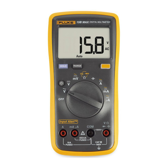
15B MAX/17B MAX Users Manual Instrument Overview Figure 1 for a description of each of the Product terminals. See Figure 2 for a description of the Product display. Figure 1. Terminals Item Description Input terminal for ac and dc current measurement to 10 A and frequency (17B MAX only) measurements. - Page 7 Digital Multimeters Instrument Overview Figure 2. Display Item Description Item Description Relative measurement is enabled (17B MAX only) Resistance or Frequency selected (17B MAX only) High voltage Farads for capacitance Continuity selected Millivolts or volts Display hold enabled DC or ac voltage or current MIN or MAX mode enabled (17B MAX only) Microamp, milliamp, or amp Celsius (17B MAX only)
-
Page 8: Auto Sleep
15B MAX/17B MAX Users Manual Auto Sleep Auto Backlight Off To power the Product on, turn the rotary switch from OFF to The backlight automatically turns off after 2 minutes of the necessary position. The Product automatically sleeps inactivity. after 20 minutes of inactivity. -
Page 9: Manual And Auto Range Selection
Digital Multimeters Measurements Manual and Auto Range Selection Data Hold The Product has both manual and auto range options. In the XW Warning Auto Range mode, the Product selects the best range for the input detected. This allows you to switch test points To prevent possible electrical shock, fire or without the need to reset the range. -
Page 10: Relative Measurements (17B Max Only)
15B MAX/17B MAX Users Manual Relative Measurements (17B MAX only) Measure AC and DC Voltage The Product allows relative measurements for all functions To measure ac and dc voltage: except frequency, resistance, continuity, duty cycle, and 1. Turn the rotary switch to K, L, or M to choose ac or dc. -
Page 11: Measure Ac Or Dc Current
Digital Multimeters Measurements Measure AC or DC Current Figure 4. Measure AC and DC Current XWWarning To prevent possible electrical shock, fire, or personal injury, remove circuit power before you connect the Product in the circuit when you measure current. Connect the Product in series with the circuit. -
Page 12: Input Alert Tm Feature
15B MAX/17B MAX Users Manual Figure 5. Input Alert Indicators Input Alert Feature WCaution To prevent circuit damage and a possible blown current fuse, do not place the probes across (in parallel with) a powered circuit when a lead is plugged into a current terminal. -
Page 13: Test For Continuity
Digital Multimeters Measurements Test for Continuity Test Diodes To test for continuity: W Caution 1. Select resistance mode. To prevent possible damage to the Product or to 2. Push B once to activate the continuity beeper. If the the equipment under test, disconnect circuit Ω... -
Page 14: Measure Capacitance
15B MAX/17B MAX Users Manual Measure Capacitance Measure Temperature (17B MAX only) To measure temperature: W Caution 1. Turn the rotary switch to S. To prevent damage to the Product, disconnect 2. Plug the K type thermocouple plug marked + into the W... -
Page 15: Hazardous Voltage Alert Led (17B Max Only)
Digital Multimeters Maintenance Maintenance Hazardous Voltage Alert LED (17B MAX only) Beyond battery and fuse replacement, do not attempt to repair or service the Product unless you are qualified to do To alert you to the presence of a potentially hazardous so and have the relevant calibration, performance test, and voltage, the hazardous voltage alert LED (X) illuminates service instructions. -
Page 16: General Maintenance
15B MAX/17B MAX Users Manual General Maintenance If the display reads OL, replace the fuse and test again. Periodically wipe the case with a damp cloth and mild If the display shows any other value, have the detergent. Do not use abrasives or solvents. Dirt or ... -
Page 17: Replace Batteries And Fuses
Digital Multimeters Maintenance Replace Batteries and Fuses To replace the batteries or fuses, see Figure Figure 8. Replace Batteries and Fuses XW Warning To prevent false readings, which could lead to possible electric shock or personal injury, replace the batteries as soon as the battery indicator (b) appears. -
Page 18: Service And Parts
Battery, IEC LR6 376756 The TL31 Test Leads that come with the Product 15B MAX- 02, 15B MAX KIT, 17B MAX-02, and 17B MAX KIT have fine Battery door assembly 5338510 tips to test small components of the circuit. With the... -
Page 19: Test Small Components In Circuit
The end of the probe should come out of the cap end. 2. Fluke recommends that you clamp the caps on the test cables close to DMM. W Warning 3. Connect the bare tips to small components on the To prevent possible personal injury, do not push circuit to do the measurement. -
Page 20: Specifications
15B MAX/17B MAX Users Manual Specifications Altitude Operating..........2000 m General Specifications Storage............12 000 m Maximum voltage between Temperature Coefficient......0.1 X (specified accuracy) /°C (<18 °C or any Terminal and Earth Ground....600 V >28 °C) Maximum differential voltage Fuse protection for between V and COM terminals ....1000 V... - Page 21 Digital Multimeters Specifications Electromagnetic Compatibility (EMC) International .......... IEC 61326-1: Portable Electromagnetic Environment CISPR 11: Group 1, Class A Group 1: Equipment has intentionally generated and/or uses conductively-coupled radio frequency energy that is necessary for the internal function of the equipment itself. Class A: Equipment is suitable for use in all establishments other than domestic and those directly connected to a low-voltage power supply network that supplies buildings used for domestic purposes.
-
Page 22: Accuracy Specifications
15B MAX/17B MAX Users Manual Accuracy Specifications Accuracy is specified for 1 year after calibration, at operating temperatures of 18 °C to 28 °C, relative humidity at 0 % to 75 %. Accuracy specifications take the form of: ±([% of Reading] + [Number of Least Significant Digits]). -
Page 23: Ac And Dc Current
AC/DC Current μA: 100 μV / μA AC/DC Current mA: 2 mV/mA AC/DC Current A: 0.03 V/A Accuracy Function Range Resolution 15B MAX 17B MAX AC Current μA 400.0 μA 0.1 μA (40 Hz to 400 Hz) 1.5 % + 3 1.5 % + 3... -
Page 24: Diode Test, Temperature, Resistance, Capacitance, Frequency, And Duty Cycle
15B MAX/17B MAX Users Manual Diode Test, Temperature, Resistance, Capacitance, Frequency, and Duty Cycle Accuracy Function Range Resolution 15B MAX 17B MAX Diode Test 2.000 V 0.001 V 10 % 10 % 50.0 °C to 400.0 °C 2 % + 1 °C Temperature 0 °C to 50.0 °C... -
Page 25: Continuity Threshold
Digital Multimeters Specifications Accuracy Function Range Resolution 15B MAX 17B MAX 50.00 Hz 0.01 Hz 500.0 Hz 0.1 Hz Frequency 5.000 kHz 0.001 kHz 0.1 % + 3 (10 Hz to 100 kHz) 50.00 kHz 0.01 kHz 100.0 kHz 0.1 kHz 1 % to 99 % 0.1 %... -
Page 26: Input Characteristics
15B MAX/17B MAX Users Manual Input Characteristics Input Impedance Common Mode Normal Mode Function Overload Protection (Nominal) Rejection Ratio Rejection Ratio >60 dB at AC Volts >10 MΩ, <100 pF 1000 V 50 Hz or 60 Hz >80 dB at AC Millivolts >1 MΩ, <100 pF...
Need help?
Do you have a question about the 15B MAX and is the answer not in the manual?
Questions and answers