
Related Manuals for Panasonic KX-MB783BR


Summary of Contents for Panasonic KX-MB783BR
- Page 1 ORDER NO.KMF0801151CE Multi-Function printer KX-MB783BR Model No. (for Brazil) © 2008 Panasonic Communications Co., Ltd. All rights reserved. Unauthorized copying and distribu- tion is a violation of law.
-
Page 2: Table Of Contents
KX-MB783BR TABLE OF CONTENTS PAGE PAGE 1 Safety Precautions -----------------------------------------------3 11.3. SERVICE MODE SETTINGS (Example of a 1.1. FOR SERVICE TECHNICIANS ------------------------3 printed out list)-------------------------------------------- 90 1.2. AC CAUTION -----------------------------------------------3 11.4. HISTORY (Example of a printed out list) ---------- 91 1.3. -
Page 3: Safety Precautions
KX-MB783BR 1 Safety Precautions 1. Before servicing, unplug the AC power cord to prevent an electric shock. 2. When replacing parts, use only the manufacturer's recommended components. 3. Check the condition of the power cord. Replace if wear or damage is evident. -
Page 4: Personal Safety Precautions
KX-MB783BR 1.3. PERSONAL SAFETY PRECAUTIONS 1.3.1. MOVING SECTIONS OF THE UNIT Be careful not to let your hair, clothes, fingers, accessories, etc., become caught in any moving sections of the unit. The moving sections of the unit are the rollers and a gear. There is a separation roller and a document feed roller which are rotated by the document feed motor. -
Page 5: Warning
KX-MB783BR 2 Warning 2.1. ABOUT LEAD FREE SOLDER (PbF: Pb free) Note: In the information below, Pb, the symbol for lead in the periodic table of elements, will refer to standard solder or solder that con- tains lead. We will use PbF solder when discussing the lead free solder used in our manufacturing process which is made from Tin, (Sn), Silver, (Ag), and Copper, (Cu). -
Page 6: Discarding Of P. C. Board
KX-MB783BR 2.2. Discarding of P. C. Board When discarding P. C. Board, delete all personal information such as telephone directory and caller list or scrap P. C. Board. 2.3. INSULATION RESISTANCE TEST 1. Unplug the power cord and short the two prongs of the plug with a jumper wire. -
Page 7: Specifications
KX-MB783BR 3 Specifications Applicable Lines: Public Switched Telephone Network Document Size: Max. 216 mm in width Max. 600 mm in length Effective Scanning Width: 208 mm Effective Printing Width: Letter/ Legal: 208 mm A4: 202 mm Transmission Time*: Approx. 4 s/page (ECM-MMR Memory transmission)**... -
Page 8: General/Introduction
KX-MB783BR 4 General/Introduction 4.1. OPTIONAL ACCESSORIES Model No. Description Specifications KX-FAT92A Replacement toner cartridge 1 toner cartridge KX-FAD93A Replacement drum unit 1 drum unit 4.2. TRANSLATION LISTS 4.2.1. HELP FUNCTION... -
Page 9: Error Message
KX-MB783BR 4.3. ERROR MESSAGE 4.3.1. DISPLAY... - Page 10 KX-MB783BR 4.3.2. REPORT 4.3.3. OTHERS...
-
Page 11: Features
KX-MB783BR 5 Features 5.1. General Features General sized characters. • Help function FINE: For originals with small printing. Display: SUPER FINE: For originals with very small printing. 1. BASIC SETTINGS PHOTO: For originals containing photographs, shaded draw- 2. FEATURE LIST ing, etc. -
Page 12: Technical Descriptions
KX-MB783BR 6 Technical Descriptions 6.1. CONNECTION DIAGRAM... -
Page 13: General Block Diagram
KX-MB783BR 6.2. GENERAL BLOCK DIAGRAM MAIN UNIT SOC (IC300) This custom IC is used for general MFP operations. ARM9 operating at 250MHz. SDRAM Controller Controls SDRAM Memory. USB Controller with PHY Apply to USB2.0 HS Scanner I/F Controls the CIS and AFE, and process the scan images. - Page 14 KX-MB783BR...
-
Page 15: Main Board Section
KX-MB783BR 6.3. MAIN BOARD SECTION 6.3.1. Data Flow [FAX Tx] 1. An analog image data is output from CIS unit to IC503. IC503 decode the analog data to digital data, and output to IC300. Scanner I/F in IC300 process image data and store it in IC400 through SDRAM I/F. - Page 16 KX-MB783BR [PC Scan] 1. An analog image data is output from CISunit to IC503. IC503 decode the analog data to digital data, and output to IC300. Scanner I/F in IC300 process image data and store it in IC400 through SDRAM I/F.
- Page 17 KX-MB783BR [Copy] 1. An analog image data is output from CISunit to IC503. IC503 decode the analog data to digital data, and output to IC300. Scanner I/F in IC300 process image data and store it in IC400 through SDRAM I/F.
- Page 18 KX-MB783BR Description of Pin Distribution (IC300) SOC (System On Chip) PIN NO. PinName POWER SUPPLY VOLTAGE EXPLANATION LEDONB 3.3V SCANNER INTERFACE NCCDON 3.3V SCANNER INTERFACE AFEMCLK 3.3V SCANNER INTERFACE NCCDCP 3.3V NOT USED CCDCLK 3.3V NOT USED PIO29 3.3V OPERATION PANEL INTERFACE PIO57 3.3V...
- Page 19 KX-MB783BR PIN NO. PinName POWER SUPPLY VOLTAGE EXPLANATION AC26 BSPCLK 3.3V NCU INTERFACE AD01 SDMD14 3.3V SDRAM DATA BUS 14 AD02 SDMD15 3.3V SDRAM DATA BUS 15 AD03 AD04 NBATRST 3.3V BATTERY RESET INPUT AD05 VDD2RTC 1.2V POWER SUPPLY AD06 3.3V...
- Page 20 KX-MB783BR PIN NO. PinName POWER SUPPLY VOLTAGE EXPLANATION AF16 USBXOUT 3.3V CRYSTAL(12MHz) OUTPUT AF17 LSI_TMS 3.3V NOT USED AF18 LSI_TCK 3.3V NOT USED AF19 LSI_CW_TAP 3.3V NOT USED AF20 PSCIO0 3.3V INPUT PORT (REGIST) AF21 PSCIO4 3.3V NOT USED AF22 PSCIO12 3.3V...
- Page 21 KX-MB783BR PIN NO. PinName POWER SUPPLY VOLTAGE EXPLANATION VDD1.2 1.2V POWER SUPPLY PIO32 3.3V OPERATION PANEL INTERFACE CRMPWR 3.3V MOTOR CURRENT CONTROL PIO56 3.3V ADF MOTOR INTERFACE VDD1.2 1.2V POWER SUPPLY PIO48 3.3V FAN2 CONTROL PIO44 3.3V DC MOTOR INTERFACE VDD3.3...
- Page 22 KX-MB783BR PIN NO. PinName POWER SUPPLY VOLTAGE EXPLANATION PIO40 3.3V NOT USED PIO39 3.3V NOT USED SDMD24 3.3V SDRAM DATA BUS 24 SDMD25 3.3V SDRAM DATA BUS 25 SDMA1 3.3V SDRAM ADDRESS BUS 1 SDMAÇO 3.3V SDRAM ADDRESS BUS 0 PIO37 3.3V...
- Page 23 KX-MB783BR PIN NO. PinName POWER SUPPLY VOLTAGE EXPLANATION PIO13 3.3V NOT USED PIO12 3.3V NOT USED PIO14 3.3V NOT USED PIO15 3.3V NOT USED SDMD0 3.3V SDRAM DATA BUS 0 SDMD1 3.3V SDRAM DATA BUS 1 NSDCAS 3.3V SDRAM CAS NSDRAS 3.3V...
- Page 24 KX-MB783BR 6.3.2. RTC BACKUP CIRCUIT 1. Function This unit has a lithium battery (BAT300) which works for the Real Time Clock IC (RTC: inside IC300). The RTC continues to work, backed up by a lithium battery even when the power switch is OFF.
- Page 25 KX-MB783BR 6.3.3. MODEM CIRCUIT OPERATION The modem (Included IC300) has all the hardware satisfying the CCITT standards mentioned previously. ALL processing is controlled by the SOC (IC300) according to CCITT procedures. This modem (Included IC300) has an automatic application equalizer. With training signal 1 or 2 at the time of G3 reception, it can automatically establish the optimum equalizer.
- Page 26 Switching circuit for other interconnected telephones; Bell detection circuit; Remote fax activation circuit. Refer to NCU SECTION (P.27) for the details. 6.3.4.2. BLOCK DIAGRAM EXTRLY IC100 IC101 RING ARXD ATXD IC200 HS_MIC(+) BTXD HS_MIC(+) BRXD HS_SP(+) HS_SP(-) SP(+) SP(-) KX-MB783BR: MAIN BOARD BLOCK DIAGRAM...
-
Page 27: Ncu Section
KX-MB783BR 6.4. NCU SECTION 6.4.1. GENERAL This section is the interface between the telephone line and external telephone. It is composed of an EXT. TEL line relay (RLY100), bell detection circuit, TAM interface circuit and line amplifier. 6.4.2. EXT. TEL. LINE RELAY (RY100) 1. -
Page 28: Its
KX-MB783BR 6.5. ITS (Integrated telephone System) and MONITOR SECTION 6.5.1. GENERAL The general ITS operation is performed by IC200 which has a handset circuit. The alarm tone, the key tone, and the beep are output from Soc IC300. 6.5.1.1. TELEPHONE MONITOR 1. -
Page 29: Cis Control Section
KX-MB783BR 6.6. CIS CONTROL SECTION The scanning block of this device consists of a control circuit and a CIS (contact image sensor), and AFE (Analog Front End) include A/D Converter. When an original document is inserted and the start button pressed, pin A3 of IC300 goes to a low level and the transistor Q518 turns on. -
Page 30: Motor Drive Section
KX-MB783BR 6.7. MOTOR DRIVE SECTION 6.7.1. Engine Motor Control Circuit 1. Functions All driving forces of printer engine part are supplied by this engine motor. Engine motor is controlled so as to rotate at constant speed during printing and copying. - Page 31 KX-MB783BR <Stop operation> In order to stop the motor rotation, following 2 signals are supplied from IC300. 1. SS signal (Output pin: Pin B12/Output Signal: "L") When this signal is inverted by transistor Q502 and becomes "H", motor recognize this signal as "stop" signal.
- Page 32 KX-MB783BR 6.7.2. SCANNER MOTOR DRIVE CIRCUIT General Scanner motor drive circuit is consist of motor current control circuit ,FB (Flat Bed) motor driver and ADF (Auto Document Feeder: equipped model only) motor driver . 6.7.2.1. MOTOR CURRENT CONTROL CIRCUIT 1. Circuit explanation According to the scan speed, each motor current is controlled for appropriate value.
- Page 33 KX-MB783BR 6.7.2.2. FB (FLAT BED) MOTOR DRIVE CIRCUIT 1. Functions This motor functions for main operations including FAX transmission, FB copy and PC scan. This motor feeds CIS unit with synchronizing for reading. 2. Motor operation During motor driving, pin A8 of IC 300 become low level, then motor driver IC502 is activated.
-
Page 34: Timing Chart And Wave Form Of Scanner Motors
KX-MB783BR 6.8. TIMING CHART AND WAVE FORM OF SCANNER MOTORS Control sequence and waveform of both FB and ADF motor are almost same. 6.8.1. NORMAL 1-2 PHASE EXCITATION (HALF STEP) 1. Timing chart 2. Wave form... - Page 35 KX-MB783BR 6.8.2. FLAT TORQUE 1-2 PHASE EXCITATION (HALF STEP) 1. Timing chart 2. Wave form...
- Page 36 KX-MB783BR 6.8.3. W 1-2 PHASE EXCITATION (QUARTER STEP) 1. Timing chart 2. Wave form...
-
Page 37: Fan Motor Section
KX-MB783BR 6.8.4. DRIVE MODE OF FB AND ADF MOTOR Correspondent table of operation 6.9. FAN MOTOR SECTION These FAN are used to radiate the heat inside of the unit. 6.9.1. LEFT SIDE FAN (FAN1) When the output of pin A11 of IC300 becomes high level or pulse, Left side FAN (FAN1) is activated. - Page 38 KX-MB783BR 6.9.2. RIGHT SIDE FAN (FAN2) When the output of pin D11of IC300 becomes high level or pulse, Right side FAN (FAN2) is activated. During the FAN rotation, the pulse signal is output from pin 2 of FAN2 and input to pin W24 of IC300.
-
Page 39: Solenoid Driver Section
KX-MB783BR 6.10. SOLENOID DRIVER SECTION The solenoid drive circuit controls Resistance solenoid and Pick up Solenoid. These solenoids are designed to be driven 24V. The diodes protect transistors from reverse generated voltage when solenoids are turned off. RESISTANCE MODE IC300_T26... -
Page 40: Lsu (Laser Scanning Unit) Section
KX-MB783BR 6.11. LSU (Laser Scanning Unit) SECTION... - Page 41 KX-MB783BR...
-
Page 42: Sensors And Switches Section
KX-MB783BR 6.12. SENSORS AND SWITCHES SECTION All of the sensor and switches are shown below. Sensor Name Sensor Location Reference number Message Error Pickup sensor Pickup & Fan2 PCB SW50 [PAPER JAMMED] [CHECK REAR CVR] [WRONG PAPER & PRESS START]... - Page 43 KX-MB783BR 6.12.1. DRUM DETECTION DRUM SENSOR is not arranged. DRUM unit is detected when HVERR SENSOR arranged in H.V.P.S becomes effective. High Voltage ERROR Status Drum sensor Signal (IC300-P26) Abnormal DRUM can not be detected Low level Normal DRUM can be detected High level 6.12.2.
- Page 44 KX-MB783BR 6.12.3. EXIT SENSOR This sensor detects whether the recording paper exits or not. When there is a recording paper at the position of the sensor, the input signal of IC300-AD20pin becomes low level. When there is no recording paper at the position of the sensor, the input signal of IC300-AD20pin becomes high level.
- Page 45 KX-MB783BR 6.12.5. REGISTRATION & MANUAL PAPER SENSOR This sensor detects whether the recording paper is at the sensor position. When the recording paper is detected, the shelter plate lets the sensor light pass. So the photo-transistor turns on, and input signal of IC300-AF20pin becomes low level.
- Page 46 KX-MB783BR 6.12.7. DOCUMENT SENSOR This sensor detects whether a document is set in ADF or not. When a document is set in ADF, the shelter plate closes the sensor light. So the photo-transistor turns off, and input signal of IC300-AF23pin becomes high level.
- Page 47 KX-MB783BR 6.12.9. TONER SENSOR..“TONER EMPTY”, “TONER LOW”, “CHANGE DRUM” The Sensor detects whether or not the Drum unit and the toner are present. When there is not Drum unit, Hall IC (IC50) turns off, and the input signal of IC300-AE22pin (Main Board) becomes a High level over 9s.
- Page 48 KX-MB783BR 6.12.9.1. TONER DETECTION FLOW CAUTION: 1. Toner low can be judged by continuous 5-times TONER LOW signal at only printing. (It is not executed at.) 2. Toner full can be judged by continuous 3-times TONER FULL signal at initialization.
- Page 49 KX-MB783BR 6.12.9.2. Drum Detection...
-
Page 50: Operation Board Section
KX-MB783BR 6.13. OPERATION BOARD SECTION The unit consists of a LCD (Liquid crystal display), KEYs and LEDs (light-emitting diodes). They are controlled by the Gate Array (IC1) on Operation board and IC300 on Main board. The key matrix table is shown below. -
Page 51: Lcd Section
KX-MB783BR 6.14. LCD SECTION The Gate Array (IC1) works only for writing the ASCII code from the data bus (D4~D7). V0 is supplied for the LCD drive. R118 and R117 are density control resistors. Consequently, in this unit, the timing (positive clock) is generated by the LCD interface circuitry in the gate array (IC1). -
Page 52: Hvps (High Voltage Power Supply) Section
KX-MB783BR 6.15. HVPS (High Voltage Power Supply) SECTION 6.15.1. HVPS SPECIFICATION Charge (CHG) Grid Developing DC Developing AC Transfer (TRA) - Transfer (TRA) + Output Characteristics Constant current Constant voltage Constant voltage Constant voltage Constant current Constant voltage (Variable) Nominal Output Voltage 4.35KV 475±10V... - Page 53 KX-MB783BR 6.15.3. DEV DC BIAS UNIT When CHG REM is “L”, 5.425kHz PWM (Pulse Width Modulation) is input from IC300 to DEV CLK through Q504, developing voltage corresponding to the DUTY of PWM signal is output from DEV OUTPUT. Also DUTY is adjusted by the utilization of the developing unit and environmental temperature.
-
Page 54: Heat Lamp Control Circuit
KX-MB783BR 6.16. HEAT LAMP CONTROL CIRCUIT The temperature of the fixing part of the Fuser Unit is converted to a voltage by THERMISTOR and input to IC300-D19pin. The heat lamp is turned on/off by the HTRCTL signal (IC300-AD19pin) through the photo triac (PC2) and the triac (SCR51). And two thermostats are set on the AC line as the safety devices. - Page 55 KX-MB783BR...
- Page 56 KX-MB783BR 2. Safety Protection a. 2 thermostats are provided with the unit, and the heater circuit is shut down when their surface temperatures became over 160°C. b. The heater control circuit of IC300 has the built-in function that the software turns off the heater control automatically if the heater is not turned ON every a fixed time.
- Page 57 KX-MB783BR Temperature AD value HEX reading Temperature AD value HEX reading Temperature AD value HEX reading [C°] [C°] [C°] Note: The value is displayed on LCD at TEST FUNCTIONS (P.81) [#815].
- Page 58 KX-MB783BR The correspondence readings between temperature measured by fixing thermistor and HEX readings Temperature AD value HEX reading Temperature AD value HEX reading Temperature AD value HEX reading [C°] [C°] [C°]...
-
Page 59: Main Board Section
KX-MB783BR Temperature AD value HEX reading Temperature AD value HEX reading Temperature AD value HEX reading [C°] [C°] [C°] 6.17. Main Board Section 3.3V Power Supply descriptions • IC 302 decreases the output voltage when NPN transistor installed chopper amplifier type switching regulator produces 2.3A min or over at the output voltage. - Page 60 KX-MB783BR DC-DC Main Board Supply...
- Page 61 KX-MB783BR wave form...
-
Page 62: Power Supply Board Section
KX-MB783BR 6.18. POWER SUPPLY BOARD SECTION The power supply board circuit generates +7V and +24Vdc. It also supplies AC voltage to the halogen heat lamp in the fuser unit. The power supply board uses the switching regulator method. Block Diagram... -
Page 63: Mechanical Operation
KX-MB783BR 6.19. Mechanical Operation 6.19.1. PRINTING The main motor gear rotates as shown in figure. GEAR DRIVE OPC drives each part of fixing and developing. When paper is fed from the standard cassette, the plunger of solenoid is pulled to drive PICK UP ROLLER (STANDARD), then the roller starts feeding paper. - Page 64 KX-MB783BR 6.19.2. SCANNING (ADF) • DOCUMENT TRANSMISSION (ADF) The frictional force between SEPARATION ROLLER (DOC.)and SEPARATION RUBBER makes PICK UP ROLLER (DOC.) move downward from standby position to pick up paper. Pick-upped paper is separated by SEPARATION ROLLER (DOC.) and SEPARATION RUBBER (DOC.), and then fed by FEED ROLLER (DOC.).
-
Page 65: Location Of Controls And Components
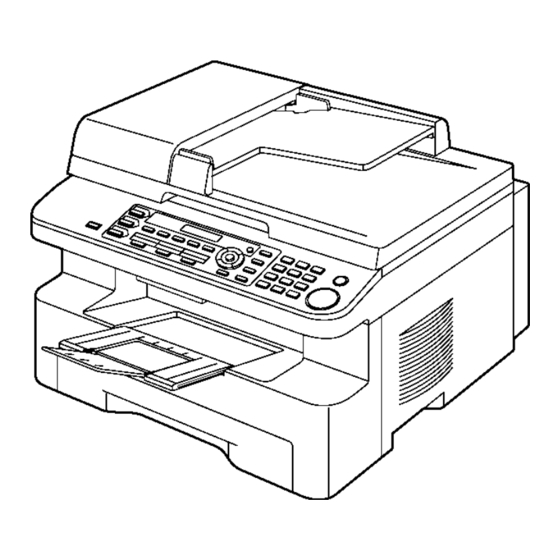
KX-MB783BR 7 Location of Controls and Components 7.1. OVERVIEW 7.1.1. Front view (1) Top cover (2) ADF (Auto Document Feeder) cover (3) Document guides (4) Document cover (5) Output tray (6) Top cover release lever (7) Document entrance (8) Paper input tray... -
Page 66: Control Panel
KX-MB783BR 7.2. CONTROL PANEL (1) COPY (2) SCAN (3) COLLATE (3) DIRECTORY (4) CONTRAST (5) RESOLUTION (6) ZOOM (6) QUICK SCAN (7) PAGE LAYOUT (8) SET (9) MENU (10) CALLER ID (11) REDIAL/PAUSE (12) STOP (13) FAX AUTO ANSWER (14) FAX... -
Page 67: Installation Instructions
KX-MB783BR 8 Installation Instructions 8.1. INSTALLATION 8.1.1. OUTPUT TRAY Pull the output tray extender (1) forward gently until it clicks into place, then press the centre part of the extender (2) to open. Note: • The output tray can hold up to approximately 150 sheets of printed paper. Remove the printed paper before the output tray becomes full. - Page 68 KX-MB783BR 8.1.2. RECORDING PAPER 8.1.2.1. Using the paper input tray The paper input tray unit can hold: — Up to 250 sheets of 60 g/m to 75 g/m paper. — Up to 230 sheets of 80 g/m paper. — Up to 200 sheets of 90 g/m paper.
- Page 69 KX-MB783BR Adjust the recording paper guides. Pinch the front side of the recording paper guide (4), then slide it to match the paper size mark. Pinch the right side of the recording paper guide (5), then slide it to adjust the width to the size of the recording paper.
- Page 70 KX-MB783BR 8.1.2.2. Using the manual input tray You can print on plain paper and labels. The manual input tray is used only for printing with the computer and can hold one page at a time. When printing multiple pages, add a next page after the first page has been fed into the unit.
- Page 71 KX-MB783BR 8.1.3. DOCUMENTS THE UNIT CAN SEND Note: • Confirm that there are no documents on the scannerglass. • Check that ink, paste or correction fluid has dried completely. • Remove clips, staples or other fasteners. • Do not set the following types of documents: (Make a copy of the document using the scanner glass and set the copy instead.)
- Page 72 • We cannot be responsible for any damage to the unit or degradation of print quality which may occur from the use of a non-Panasonic toner cartridge and drum unit. • The drum unit contains a photosensitive drum. Exposing it to light may damage the drum. Once you have opened the protection bag: —...
- Page 73 KX-MB783BR Turn the lever (5) on each side of the toner cartridge while pressing down firmly. Make sure that the triangles (6) match, to install the toner cartridge cor- rectly. Lift the top cover release lever (7) and open the top cover (8).
- Page 74 KX-MB783BR Install the drum and toner unit (11) by holding the tabs. • Make sure that the triangles (12) match, to install the drum and toner unit correctly. Close the top cover until locked.
- Page 75 KX-MB783BR Caution: • To prevent injuries, be careful not to put your hands under the top cover. Toner save feature • If you want to reduce toner consumption, set the toner save setting to ON (feature #482). The toner cartridge will last approxi- mately 40% longer.
- Page 76 KX-MB783BR 8.1.5. CONNECTING TO A COMPUTER Panasonic Multi-Function Station software enables the unit to carry out the following functions: - Printing on plain paper and labels - Scanning documents and converting an image into text with OCR software - Scanning from other applications for Microsoft® Windows® that support TWAIN scanning...
- Page 77 KX-MB783BR For USB connection 1. [Connect directly with a USB cable.] → [Next] • The [Connect Device] dialogue box will appear. 2. Connect the unit with the USB cable (1), then click [Next]. • If the unit is connected to your computer, the model name will be automatically detected.
-
Page 78: Connections
KX-MB783BR 8.2. CONNECTIONS Caution: • When you operate this product, the power outlet should be near the product and easily accessible. (1) Power cord • Connect to a power outlet. (127 V, 60 Hz). (2) Telephone line cord • Connect to a single telephone line jack. -
Page 79: Operating Instructions
KX-MB783BR 9 Operating Instructions 9.1. YOUR LOGO You can program your logo (name, company name, etc.) so that it appears on the top of each page sent. • For entering characters, only the English alphabet, numbers and symbols are available. Chinese characters cannot be entered. - Page 80 KX-MB783BR 9.1.1. TO SELECT CHARACTERS WITH THE DIAL KEYPAD The dial keypad is used to enter characters and numbers. - Press [ ] or [ ] to move the cursor. - Press dial keys to enter characters and numbers. - Press [STOP] to erase the character or number highlighted by the cursor. Press and hold [STOP] to erase all characters or num- bers.
-
Page 81: Test Mode
KX-MB783BR 10 Test Mode 10.1. TEST FUNCTIONS The codes listed below can be used to perform simple checks of some of the unit’s functions. When complaints are received from customers, they provide an effective tool for identifying the locations and causes of malfunctions. - Page 82 KX-MB783BR Test Mode Type of Mode Code Function Operation after code input SENSOR CHECK Service Mode “8” “1” “5” First of all, press the copy button, and confirm the action of ON/OFF. For each sensor’s operation, refer to SENSORS AND SWITCHES SECTION (P.42).
- Page 83 KX-MB783BR 10.1.1. DTMF SINGLE TONE TRANSMIT SELECTION Note: After performing this check, do not forget to turn the setting off. otherwise, dialing in DTMF signal will not work. 10.1.2. BUTTON CODE TABLE...
- Page 84 KX-MB783BR 10.1.3. PRINT TEST PATTERN 1. NO.01 3. NO.03 2. NO.06 • These print test patterns are just image printing, and differ- ent from actual ones. • When it is required to judge the print quality, compare with the printing of a nondefective machine.
-
Page 85: Service Mode
KX-MB783BR 11 Service Mode The programming functions are used to program the various features and functions of the machine, and to test the machine. This facilitates communication between the user and the service man while programming the unit. 11.1. PROGRAMMING AND LISTS 11.1.1. - Page 86 KX-MB783BR 11.1.3. SERVICE FUNCTION TABLE Code Function Set Value Effective Default Remarks Range Pause time set X 100 msec 001~600 ---------- Dial speed select 1:10 pps 1, 2 ---------- 2:20 pps V34 transmission start speed 0: Disable If the code 527 is set at 2, the code 507 and 508 1: 33.6...
- Page 87 KX-MB783BR Code Function Set Value Effective Default Remarks Range Time between CED and 300bps 1:75 msec See Symptom/Countermeasure Table for long 2:500 msec distance and international calls in (P.141). Refer to 3:1 sec (P.135) and (P.141). Overseas DIS detection select...
- Page 88 KX-MB783BR 11.1.4. Memory Clear Specification Execute Service Mode #550 when you want to reset the all setting data keeping the user information. Execute Service Mode #710 to clear the user information in case that Main Unit is recycled. Note: Please restart a power supply after clearing a memory.
-
Page 89: User Mode (The List Below Is An Example Of The System Setup List The Unit Prints Out.)
KX-MB783BR 11.2. USER MODE (The list below is an example of the SYSTEM SETUP LIST the unit prints out.) Note: The above values are the default values. -
Page 90: Service Mode Settings (Example Of A Printed Out List)
KX-MB783BR 11.3. SERVICE MODE SETTINGS (Example of a printed out list) Note: The above values are the default values. -
Page 91: History (Example Of A Printed Out List)
KX-MB783BR 11.4. HISTORY (Example of a printed out list) Note: See the following descriptions of this report. Item No. (1) ~ (49) are corresponding to the listed items in DESCRIPTIONS OF THE HISTORY REPORT(P.92). - Page 92 KX-MB783BR 11.4.1. DESCRIPTIONS OF THE HISTORY REPORT (1) ROM VERSION (27) NUMBER OF PC-PRINT FLASH ROM version The number of times multifunction was used for the Printer. (2) SUM (The number of pages printed. If the unit does not have a FLASH ROM internal data calculation.
- Page 93 KX-MB783BR (59) Not used (60) Total number of printing (The number of printed papers including copy, reception printing, report, etc.) (61) Not used (62) Not used...
-
Page 94: Troubleshooting Guide
KX-MB783BR 12 Troubleshooting Guide 12.1. USER RECOVERABLE ERRORS If the unit detects a problem, one or more of the following messages will appear on the display. The explanations given in the [ ] are for servicemen only. DISPLAY MESSAGE CAUSE AND REMEDY •... - Page 95 KX-MB783BR DISPLAY MESSAGE CAUSE AND REMEDY - “#2”: Manual input tray • Recording paper is not installed or the paper input tray has run out of paper. Install paper. • Recording paper is not fed into the unit properly. Reinstall paper.
-
Page 96: Remote Programming
KX-MB783BR 12.2. REMOTE PROGRAMMING If, after the call is connected, the customer describes the situation and it is determined that the problem can be corrected by making parameter changes, this function makes it possible to change parameters such as the user code and service code from another fax (using DTMF tones). - Page 97 KX-MB783BR 12.2.1. ENTERING THE REMOTE PROGRAMMING MODE AND CHANGING SERVICE CODES CROSS REFERENCE: PROGRAM MODE TABLE (P.98)
- Page 98 KX-MB783BR 12.2.2. PROGRAM MODE TABLE 12.2.2.1. USER FUNCTION Basic features Code Function Set Value Default Remote Setting QUICK SETUP --------- None SET DATE & TIME dd/mm/yy 01/01/07 YOUR LOGO --------- None YOUR FAX NUMBER --------- None LANGUAGE 2:English / 3:PORTUGUESE...
- Page 99 KX-MB783BR LAN features Code Function Set Value Default Remote Setting DHCP 1:DISABLED / 2:ENABLED ENABLED IP ADDRESS --------- SUBNET MASK --------- DEFAULT GATEWAY --------- PRIMARY DNS SERVER --------- SECONDARY DNS SERVER --------- MACHINE NAME --------- MAC ADDRESS --------- APPROVED USERS...
- Page 100 KX-MB783BR 12.2.2.2. SERVICE FUNCTION Code Function Set Value Default Remote Setting Pause time set 001~600 x 100msec Dial speed 1:10pps / 2:20 pps 10pps V34 transmission start speed (0:Disable/1:33.6/2:31.2/3:28.8/4:26.4/ 33600bps 5:24.0/6:21.6/7:19.2/8:16.8/) V34 reception start speed (0:Disable/1:33.6/2:31.2/3:28.8/4:26.4/ 33600bps 5:24.0/6:21.6/7:19.2/8:16.8/) Bell signal detect time...
- Page 101 KX-MB783BR Note: Refer to SERVICE FUNCTION TABLE (P.86) for descriptions of the individual codes. Example: If you want to set value in the “401 PRINT SENDING REPORT”, press the dial key number 1, 2 or 3 corresponding to the Set...
-
Page 102: Troubleshooting Details
KX-MB783BR 12.3. TROUBLESHOOTING DETAILS 12.3.1. OUTLINE Troubleshooting is for recovering quality and reliability by determining the broken component and replacing, adjusting or cleaning it as required. First, determine the problem then decide the troubleshooting method. If you have difficulty finding the broken part, determine which board is broken. - Page 103 KX-MB783BR 12.3.3. INITIALIZATION There are two types of initialization, one is the short initialization (about 3 seconds) and the other is the long initialization (about 10 seconds). The short initialization makes the unit enter the standby mode. The long initialization makes the unit enter the...
- Page 104 KX-MB783BR 12.3.4. SIMPLE CHECK LIST Note: Check according to the service code referring to TEST FUNCTIONS (P.81)
- Page 105 KX-MB783BR 12.3.5. SIMPLIFIED TROUBLESHOOTING GUIDE 12.3.5.1. PRINTING Symptom Cause Countermeasure GHOST IMAGE (P.115) Failed drum unit Replace drum unit Failed transfer unit Check the transfer roller and spring Failed the high-voltage terminal Check the high-voltage terminal Failed the high voltage power supply board Go to HIGH VOLTAGE SECTION (P.165)
- Page 106 KX-MB783BR 12.3.5.2. RECORDING PAPER FEED Symptom Cause Countermeasure MULTIPLE FEED (P.121) Dirty or failed the pickup roller Clean or replace the pickup roller Dirty or failed the pickup rubber Clean or replace the separation rubber THE RECORDING PAPER Dirty the pressure roller or the heat roller...
- Page 107 KX-MB783BR 12.3.5.3. COPY AND FAX Symptom Cause Countermeasure DOCUMENT FEED Failed the document sensor lever Replace the document sensor lever DOCUMENT Failed the document sensor Go to SENSOR SECTION (P.154) FEED,DOCUMENT Dirty or failed the separation roller Clean or replace the separation roller...
- Page 108 KX-MB783BR 12.3.6. CALL SERVICE TROUBLESHOOTING GUIDE Call Service related error is most frequent. Call Service 1 ----- Polygon doesn’t rotate..Refer to LSU (Laser Scanning Unit) SECTION (P.40). • First, listen to the sound. If rotation sound isn't heard, check 24V line, POLON signal and POLCLK signal. If even a little of sound is heard, check XREADY signal.
- Page 109 KX-MB783BR 12.3.6.1. CALL SERVICE 1 "CALL SERVICE 1" means that the polygon motor inside the LSU does not rotate. The rotation of the polygon motor is detected by IC300-F23pin (NREADY).
- Page 110 KX-MB783BR 12.3.6.2. CALL SERVICE 2 "CALL SERVICE 2" means that the synchronous signal out of the LSU cannot be detected. The synchronous signal out of the LSU is detected by IC 300-G23pin. (NHSYNC) Note: As for the "Pulse" waveform of the above flow chart, see the timing chart.
- Page 111 KX-MB783BR 12.3.6.3. CALL SERVICE 3 "CALL SERVICE 3" means that the temperature of the fuser does not rise up to or exceed a constant temperature. The temperature is monitored with the thermistor inside the fuser and detected with the voltage input into IC 300-D19.
- Page 112 KX-MB783BR 12.3.6.4. CALL SERVICE 4 "CALL SERVICE 4" means that the FAN does not run or the running of the FAN cannot be detected normally. The running of the FAN is detected by IC300-AC20 and W24pin. "CALL SERVICE 4" is displayed when it detects NG three times continuously.
- Page 113 KX-MB783BR 12.3.6.5. CALL SERVICE 5 “CALL SERVICE 5” means that Engine DC motor’s rotation detection signal (LD) does not become Low.
- Page 114 KX-MB783BR 12.3.6.6. CALL SERVICE 6 “CALL SERVICE 6” indicates that abnormal charge voltage is output from the high voltage unit.
- Page 115 KX-MB783BR 12.3.7. PRINT 12.3.7.1. GHOST IMAGE CROSS REFERENCE: HIGH VOLTAGE SECTION(P.165) POWER SUPPLY BOARD SECTION(P.62)
- Page 116 KX-MB783BR 12.3.7.2. DARK OR WHITE VERTICAL LINE Note: When wiping the cover glass, reflecting mirror, use a dry and soft cloth.
- Page 117 KX-MB783BR 12.3.7.3. DARK OR WHITE HORIZONTAL LINE CROSS REFERENCE: HIGH VOLTAGE SECTION (P.165)
- Page 118 KX-MB783BR 12.3.7.4. DIRTY OR HALF DARKNESS BACKGROUND CROSS REFERENCE: HIGH VOLTAGE SECTION (P.165)
- Page 119 KX-MB783BR 12.3.7.5. BLACK PRINT CROSS REFERENCE: HIGH VOLTAGE SECTION (P.165) LSU (Laser Scanning Unit) SECTION (P.40)
- Page 120 KX-MB783BR 12.3.7.6. LIGHT PRINT CROSS REFERENCE: HIGH VOLTAGE SECTION (P.165)
- Page 121 KX-MB783BR 12.3.7.7. BLACK OR WHITE POINT 12.3.8. RECORDING PAPER FEED 12.3.8.1. MULTIPLE FEED...
- Page 122 KX-MB783BR 12.3.8.2. THE RECORDING PAPER IS WAVED OR WRINKLED...
- Page 123 KX-MB783BR 12.3.8.3. SKEW...
- Page 124 KX-MB783BR 12.3.8.4. THE RECORDING PAPER DOES NOT FEED CROSS REFERENCE: SENSOR SECTION (P.154) ENGINE MOTOR (P.157)
- Page 125 KX-MB783BR 12.3.8.5. THE RECORDING PAPER JAM...
- Page 126 KX-MB783BR CROSS REFERENCE: FAN MOTOR SECTION (P.37) When the recording paper jam is occurred, the service mode *630 distinguishes the cause. 0:No Paper Jam 1:The paper was pulled into the unit. 2:The paper was longer than the maximum length of the Resistance sensor.
- Page 127 KX-MB783BR 12.3.9. ADF (Auto Document Feeder) SECTION 12.3.9.1. NO DOCUMENT FEED,DOCUMENT JAM and MULTIPLE DOCUMENT FEED. CROSS REFERENCE: SENSOR SECTION (P.154)
- Page 128 KX-MB783BR CROSS REFERENCE: ENGINE MOTOR (P.157)
- Page 129 KX-MB783BR 12.3.9.2. SKEW (ADF)
- Page 130 KX-MB783BR 12.3.9.3. THE SENT FAX DATA IS SKEWED CROSS REFERENCE: SKEW (ADF) (P.129) 12.3.9.4. THE RECEIVED FAX DATA IS SKEWED CROSS REFERENCE: SKEW (P.123) 12.3.9.5. THE RECEIVED OR COPIED DATA IS EXPANDED...
- Page 131 KX-MB783BR 12.3.9.6. BLACK OR WHITE VERTICAL LINE IS COPIED...
- Page 132 KX-MB783BR 12.3.10. AN ABNORMAL IMAGE IS COPIED CROSS REFERENCE: CIS CONTROL SECTION (P.161) 12.3.11. COMMUNICATION SECTION Find the problem in the table shown below, and refer to the corresponding troubleshooting procedure in DEFECTIVE FACSIM- ILE SECTION (P.133). Symptom Content Possible cause The paper dose not feed properly when faxing.
- Page 133 KX-MB783BR 12.3.11.1. DEFECTIVE FACSIMILE SECTION 12.3.11.1.1. TRANSMIT PROBLEM CROSS REFERENCE: CLEANING THE WHITE PLATE AND GLASSES (P.217) ADF (Auto Document Feeder) SECTION (P.127) OPERATION PANEL SECTION (P.154)
- Page 134 KX-MB783BR 12.3.11.1.2. SOMETIME THERE IS A TRANSMIT PROBLEM Note: “596: Transmit level set” represents a service code. Refer to the SERVICE FUNCTION TABLE (P.86). “717: Transmit speed select” represents a service code. Refer to the SERVICE FUNCTION TABLE (P.86).
- Page 135 KX-MB783BR 12.3.11.1.3. RECEIVE PROBLEM Confirm the following before starting troubleshooting. • Is the recording paper installed properly? Refer to the next page. Note: “596: Transmit level set” represents a service code. Refer to the SERVICE FUNCTION TABLE (P.86). “718: Receive speed select” represents a service code. Refer to the SERVICE FUNCTION TABLE (P.86).
- Page 136 KX-MB783BR 12.3.11.1.4. THE UNIT CAN COPY, BUT CANNOT TRANSMIT/RECEIVE CROSS REFERENCE: TEST FUNCTIONS (P.81) CHECK SHEET (P.151)
- Page 137 KX-MB783BR 12.3.12. SPECIAL SERVICE JOURNAL REPORTS Journal 2 and Journal 3 shown below, which are special journals giving the additional detailed information about the latest 35 communications, can be printed by Service Code 881 or 882. Remote printing function for the journal reports (JOURNAL, JOURNAL 2 and JOURNAL 3) is also available for service technicians.
- Page 138 KX-MB783BR 12.3.12.1. JOURNAL 2 Refer to JOURNAL 2 in PRINTOUT EXAMPLE(P.139). Journal 2 displays the additional detailed information about the last 35 communications. Descriptions: (1) RCV. MODE Indicates which receive mode the unit was in when the unit received a fax message.
- Page 139 KX-MB783BR 12.3.12.2. JOURNAL 3 Refer to JOURNAL 3 in PRINTOUT EXAMPLE(P.139). Description (6) ENCODE Compression Code: MH/MR/MMR (7) MSLT MSLT means Minimum Scan Line Time. Used only at the factory. (8) EQM EQM means Eye Quality Monitor. Used only at the factory.
- Page 140 KX-MB783BR...
- Page 141 KX-MB783BR 12.3.12.4. HOW TO OUTPUT THE JOURNAL REPORT 1. Press the MENU button 3 times. 2. Press “#”, then “3”. 3. Press the SET button. 4. The report prints out. CROSS REFERENCE: Features(P.11) Error code table: (1) CODE (2) RESULT...
- Page 142 KX-MB783BR...
- Page 143 KX-MB783BR CROSS REFERENCE: TEST FUNCTIONS (P.81)
- Page 144 KX-MB783BR CROSS REFERENCE: TEST FUNCTIONS (P.81)
- Page 145 KX-MB783BR CROSS REFERENCE: TEST FUNCTIONS (P.81)
- Page 146 KX-MB783BR CROSS REFERENCE: TEST FUNCTIONS (P.81)
- Page 147 KX-MB783BR...
- Page 148 KX-MB783BR...
- Page 149 KX-MB783BR CROSS REFERENCE: TEST FUNCTIONS (P.81)
- Page 150 KX-MB783BR 12.3.13. INITIALIZING ERROR After the power is turned on, the SOC (IC300) initializes and checks each IC. The ROM (IC402) and SDRAM (IC400) are checked. If initialization fails for the ICs, the system will not boot up. In this case, please find the cause as follows.
- Page 151 KX-MB783BR 12.3.14. ANALOG SECTION This chapter provides the testing procedures required for the analog parts. A signal route to be tested is determined depending upon purposes. For example, the handset TX route begins at the handset microphone and the signal is output to the telephone line.
- Page 152 KX-MB783BR 12.3.14.2. DEFECTIVE ITS (Integrated Telephone System) SECTION 1. No handset and speakerphone transmission / reception Perform a signal test in the ITS or the NCU section and locate a defective point (where the signal disappears) on each route between the handset microphone and telephone line (sending), or between the telephone line and the handset speaker (receiv- ing), or between the microphone and the telephone line (sending), or between the telephone line and the speaker (receiving).
- Page 153 KX-MB783BR 4. No tone dialing CROSS REFERENCE: CHECK SHEET (P.151) 12.3.14.3. DETECTIVE TAM INTERFACE SECTION 1. The FAX turns on, but does not arrive through TAM. CROSS REFERENCE: TAM INTERFACE SECTION (P.28) 2. A FAX is received, but won't switch from TAM to FAX.
- Page 154 KX-MB783BR 12.3.15. OPERATION PANEL SECTION Refer to TEST FUNCTIONS (P.81). 1. NO KEY OPERATION 2. NO LCD INDICATION CROSS REFERENCE: TEST FUNCTIONS (P.81) 12.3.16. SENSOR SECTION Refer to SENSORS AND SWITCHES for the circuit description. Perform an SENSOR CHECK to determine if the sensor is operating correctly.
- Page 155 KX-MB783BR 2. Check the paper exit sensor..“PAPER JAMMED” 3. Check the read position sensor ..“CHECK DOCUMENT” 4. Check the registration & manual paper sensor ..“PAPER JAMMED” 5. Check the print timing sensor ..“PAPER JAMMED” 6. Check the document sensor...
- Page 156 KX-MB783BR 7. Check the top cover sensor ..“TOP COVER OPEN” 8. Check the toner sensor ..“TONER LOW”, “CHANGE DRUM” CROSS REFERENCE: SENSORS AND SWITCHES SECTION (P.42)
- Page 157 KX-MB783BR 12.3.17. MOTOR SECTION 12.3.17.1. ENGINE MOTOR...
- Page 158 KX-MB783BR 12.3.17.2. FB (Flatbed) MOTOR...
- Page 159 KX-MB783BR 12.3.17.3. ADF MOTOR (ADF provided model only)
- Page 160 KX-MB783BR 12.3.18. LSU SECTION CROSS REFERENCE: LSU (Laser Scanning Unit) SECTION (P.40)
- Page 161 KX-MB783BR 12.3.19. CIS CONTROL SECTION...
- Page 162 KX-MB783BR CROSS REFERENCE: TEST FUNCTIONS (P.81)
- Page 163 KX-MB783BR 12.3.20. HIGH VOLTAGE VALUE CHECK POINT Measurement Procedure 1. Turn Off the unit, and open the unit cover. 2. Remove the developing unit, if it is equipped. 3. Connect the wire to the terminal to be measured (Fig. 2). The wire should be put out of the unit not to interfere in other termi- nals (Fig.
- Page 164 KX-MB783BR...
- Page 165 KX-MB783BR 12.3.21. HIGH VOLTAGE SECTION 1. Main...
- Page 166 KX-MB783BR 2. CHG, GRID 3. TRA (+)
- Page 167 KX-MB783BR 3. DEV DC TRA (-)
- Page 168 KX-MB783BR 12.3.22. USB SECTION Troubleshooting 1. Confirmation of the PC settings...
- Page 169 KX-MB783BR 2. Confirmation of the main unit...
- Page 170 KX-MB783BR USB (Universal Serial Bus) block Description This is a USB block for data communication with PC. Two signal lines (D+/D-) are differential signals which work in reverse phase. VBUS: CN300 1pin D+: CN300 3pin D-: CN300 2pin GND: CN300 4pin...
- Page 171 KX-MB783BR Waveform of normal operation...
- Page 172 KX-MB783BR 12.3.23. LAN SECTION LAN Block Diagram LAN Circuit signal waveform (Normal) Transmitter waveform [TD+ ( CN750 pin1), TD- ( CN750 pin2) differential voltage] : Differential probe is used. 1. When network equipment is not connected (LAN cable is not connected);...
- Page 173 KX-MB783BR 2. When 100Base-TX-enabled deviced is connected;...
- Page 174 KX-MB783BR 3. When 10Base-T-enabled device is connected.
- Page 175 KX-MB783BR IC750 ( C1CB00002227 : 3.3V Single Power Supply) Pin Description Pin No Signal Name Input/Output(*) Description MDIO Management Independent Interface ( MII ) Data I/O MII Clock Input RXD3/PHYAD1 Ipd /O MII Receive Data Output RXD2/PHYAD2 Ipd /O MII Receive Data Output...
- Page 176 KX-MB783BR Pin No Signal Name Input/Output(*) Description Ground XTAL feedback Crystal Oscillator Input VDDPLL Analog PLL 2.5V power supply RST# Chip Reset ;Active low NOTE: I=input o=output I/O = bi-directional Ipu = input w/ internal pull-up Ipd = input w/ internal pull-down...
- Page 177 KX-MB783BR 12.3.24. MAIN BOARD SECTION 3.3V TROUBLESHOOTING GUIDE...
- Page 178 KX-MB783BR 1.2V TROUBLESHOOTING GUIDE...
- Page 179 KX-MB783BR 12.3.25. POWER SUPPLY BOARD SECTION 12.3.25.1. KEY COMPONENTS FOR TROUBLESHOOTING Check the following parts first: F1, F2, D10-D13, C5, Q1 and PC1. This comes from our experience with experimental test. For example: power supply and lightning surge voltage test, with standing voltage test, intentional short circuit test, etc.
- Page 180 KX-MB783BR 12.3.25.2. TROUBLESHOOTING FLOW CHART 12.3.25.3. BROKEN PARTS REPAIR DETAILS (D10~D13) Check for a short-circuit in terminal 4. If D10~D13 is short-circuit, F2 will melt (open). In this case, replace all of the parts (D10 - D13, F2). (D101) If D101 is broken, the oscillation circuit in the power supply cannot operate. Check it with an electric tester.
-
Page 181: Document Jams (Auto Document Feeder)
KX-MB783BR 12.4. DOCUMENT JAMS (AUTO DOCUMENT FEEDER) Caution: • Do not pull out the jammed document forcibly before lifting the ADF cover. Open the ADF cover (1) while holding the document cover (2). Remove the jammed document (3) carefully. When the document has jammed near the document entrance:... - Page 182 KX-MB783BR When the document has jammed near the document exit: Close the ADF cover.
-
Page 183: Recording Paper Jam
KX-MB783BR 12.5. RECORDING PAPER JAM 12.5.1. When the recording paper has jammed inside of the unit The display will show the following. Caution: • Do not pull out the jammed paper forcibly before opening the top cover. Case 1: When the recording paper has jammed near the manual input tray: 1. - Page 184 KX-MB783BR 3. Close the paper input tray. • Open and close the top cover (4) to clear the error message. Case 2: When the recording paper has jammed near the drum and toner unit: 1. Pull open the paper input tray (1).
- Page 185 KX-MB783BR 3. Remove the jammed paper (6) carefully by pulling it upwards. Remove the jammed paper (7) carefully by pulling it toward you. 4. Close the paper input tray.
- Page 186 KX-MB783BR 5. Close the top cover until locked. Caution: • To prevent injuries, be careful not to put your hands under the top cover. Case 3: When the recording paper has jammed near the fuser unit: 1. Lift the top cover release lever (1) and open the top cover (2).
- Page 187 KX-MB783BR 2. Lift both green levers (5) until they stop. 3. Remove the jammed paper (6) carefully by pulling it upwards. 4. Push back the green levers (7) to the original position.
- Page 188 KX-MB783BR 5. Close the top cover until locked.
- Page 189 KX-MB783BR 12.5.2. When the recording paper is not fed into the unit properly The display will show the following. Pull the paper input tray until it clicks into place, then put it com- pletely out, lifting the front part of the tray. Remove the recording paper and straighten.
- Page 190 KX-MB783BR 12.5.3. When the recording paper in the manual input tray is not fed into the unit properly The display will show the following. Remove the recording paper. Re-insert the recording paper. Note: • If the error message is still displayed, check the recording paper specifications and re-install recording paper.
-
Page 191: Service Fixture & Tools
KX-MB783BR 13 Service Fixture & Tools... -
Page 192: Disassembly And Assembly Instructions
KX-MB783BR 14 Disassembly and Assembly Instructions Note: Remove the Document Cover, the Paper Input tray and the drum and toner cartridge before reassembling. -
Page 193: Adf Section
KX-MB783BR 14.1. ADF SECTION... -
Page 194: Remove Adf Section (1)
KX-MB783BR 14.2. REMOVE ADF SECTION (1) -
Page 195: Remove Adf Section
KX-MB783BR 14.3. REMOVE ADF SECTION... -
Page 196: Remove Top Cover Section
KX-MB783BR 14.4. REMOVE TOP COVER SECTION... -
Page 197: Remove Scanner Glass Section
KX-MB783BR 14.5. REMOVE SCANNER GLASS SECTION... -
Page 198: Remove Operation Panel Section
KX-MB783BR 14.6. REMOVE OPERATION PANEL SECTION... -
Page 199: Left Side Section
KX-MB783BR 14.7. LEFT SIDE SECTION 14.8. REMOVE MAIN BOARD... -
Page 200: Remove Gear Chassis Section
KX-MB783BR 14.9. REMOVE GEAR CHASSIS SECTION... -
Page 201: Remove Paper Feed Roller
KX-MB783BR 14.10. REMOVE PAPER FEED ROLLER 14.11. RIGHT SIDE SECTION... -
Page 202: Remove Right Side Cover Section
KX-MB783BR 14.12. REMOVE RIGHT SIDE COVER SECTION... -
Page 203: Lower Side Cabinet Section
KX-MB783BR 14.13. LOWER SIDE CABINET SECTION... -
Page 204: Remove Right Cassette Guide
KX-MB783BR 14.14. REMOVE RIGHT CASSETTE GUIDE 14.15. REMOVE PICK UP BOARD... -
Page 205: Remove High Voltage Power Board
KX-MB783BR 14.16. REMOVE HIGH VOLTAGE POWER BOARD... -
Page 206: Remove Pick Up Roller Unit
KX-MB783BR 14.17. REMOVE PICK UP ROLLER UNIT... -
Page 207: Remove Low Voltage Power Board
KX-MB783BR 14.18. REMOVE LOW VOLTAGE POWER BOARD... -
Page 208: Remove Fuser Unit
KX-MB783BR 14.19. REMOVE FUSER UNIT... -
Page 209: Installation Position Of The Lead
KX-MB783BR 14.20. Installation Position of The Lead 14.20.1. MAIN BAORD SECTION... - Page 210 KX-MB783BR 14.20.2. BOTTOM PART SECTION...
- Page 211 KX-MB783BR 14.20.3. SIDE CABINET SECTION...
- Page 212 KX-MB783BR 14.20.4. HIGH VOLTAGE POWER SUPPLY BOARD SECTION...
- Page 213 KX-MB783BR 14.20.5. LOW VOLTAGE POWER SUPPLY BOARD SECTION...
- Page 214 KX-MB783BR 14.20.6. AC INLET SECTION 14.20.7. SOLENOID LEAD SECTION...
-
Page 215: Maintenance
KX-MB783BR 15 Maintenance 15.1. MAINTENANCE ITEMS AND COMPONENT LOCATIONS 15.1.1. OUTLINE MAINTENANCE AND REPAIRS ARE PERFORMED USING THE FOLLOWING STEPS. 1. Periodic maintenance Inspect the equipment periodically and if necessary, clean any contaminated parts. 2. Check for breakdowns Look for problems and consider how they arose. - Page 216 KX-MB783BR 15.1.2.1. Maintenance List OPERATION CHECK REMARKS Document Path Remove any foreign matter such as paper. — Rollers If the roller is dirty, clean it with a damp cloth then dry thor- Refer to MAINTENANCE CHECK ITEMS/ oughly. COMPONENT LOCATIONS(P.215)
-
Page 217: Maintenance
KX-MB783BR 15.2. MAINTENANCE 15.2.1. CLEANING THE WHITE PLATE AND GLASSES Clean the white plate and glasses when a black line, a white line or a dirty pattern appears on: — your recording paper, — the original document, — the scanned data, or —... - Page 218 KX-MB783BR 15.2.1.2. Lower glass Disconnect the power cord. Lift the top cover release lever (1) and open the top cover (2). Note: • Do not touch the transfer roller (4). Remove the drum and toner unit (5) by holding the tabs.
- Page 219 KX-MB783BR Reinstall the drum and toner unit (7) by holding the tabs. • Make sure that the triangles (8) match, to install the drum and toner unit correctly. Close the top cover until locked.
- Page 220 KX-MB783BR Caution: • To prevent injuries, be careful not to put your hands under the top cover. Re-connect the power cord.
- Page 221 KX-MB783BR 15.2.2. CLEANING THE DOCUMENT FEEDER ROLLERS Clean the rollers when the document or recording paper frequently misfeeds. Disconnect the power cord. Open the ADF cover (1) while holding the document cover (2). Clean the document feeder roller’s surface (3) and separation rubber (4) with a cloth moistened with isopropyl rubbing alcohol, while rotating them.Let all parts dry thoroughly.
-
Page 222: Printing Operation Principle
KX-MB783BR 15.3. PRINTING OPERATION PRINCIPLE 15.3.1. PROCESS CHART AND PROCESS BIAS 15.3.2. CHARGING Charging is the stage that keeps the surface of the sensitive drum a fixed electric potential. The sensitive drum is the Organic Photo Conductor (OPC), which is a electric conductive cylinder whose surface is covered with the Charge Generation Transfer Layer (CGTL). - Page 223 KX-MB783BR 15.3.3. EXPOSING When the drum which is charged with the fixed electric charge is irradiated by the laser beam, the plus charge and minus charge are generated at the Charge Generation Transfer Layer. Passing through the Charge Generation Transfer Layer which conducts the minus charge, the plus-charged drum's surface is neutralized to be skipped.
- Page 224 KX-MB783BR 15.3.5. DEVELOPING AND TRANSCRIPTION The developing is the stage that the OPC drum with an invisible image is changed to visible by the toner. The drum unit consists of mixing paddle, toner supply roller, developing roller, developing blade, charge wire, grid plate and OPC drum. The bias voltage is added to the developing roller and toner supply roller.
- Page 225 KX-MB783BR 15.3.6. CLEANING OF TRANSFER ROLLER The toner attached to the surface of the OPC drum is transferred to the paper at the transcription stage, but a part of the toner remains. The cleaning is the stage that cleans the remain toner after the transcription stage. The remain toner on the drum and the toner which was attached to the place where the laser beam didn't scan are gathered to the developing roller to be used again.
- Page 226 KX-MB783BR 15.3.7. FIXING On the process of the transfer, the transferred toner is weakly attached on the paper. Fixing means the process to fix the toner on the paper permanently. The fixing part melts the toner at the high temperature using the halogen heater. The toner is fixed on the paper by the heat and pressure through the fixing part with the image.
-
Page 227: Terminal Guide Of The Ics
KX-MB783BR 15.4. TERMINAL GUIDE OF THE ICs TRANSISTORS AND DIODES 15.4.1. MAIN BOARD (1) - Page 228 KX-MB783BR 15.4.2. MAIN BOARD (2) 15.4.3. OPERATION BOARD...
-
Page 229: How To Replace The Flat Package Ic
KX-MB783BR 15.5. HOW TO REPLACE THE FLAT PACKAGE IC Even if you do not have the special tools (for example, a spot heater) to remove the Flat IC, with some solder (large amount), a soldering iron and a cutter knife, you can easily remove the ICs that have more than 100 pins. - Page 230 KX-MB783BR 15.5.3. FLAT PACKAGE IC INSTALLATION PROCEDURE 1. Temporarily fix the FLAT PACKAGE IC, soldering the two marked pins. *Check the accuracy of the IC setting with the corresponding soldering foil. 2. Apply flux to all pins of the FLAT PACKAGE IC.
-
Page 231: Main Board Section
KX-MB783BR 15.6. MAIN BOARD SECTION When the unit fails to boot up the system, take the troubleshooting procedures very carefully. It may have a serious problem. The symptom: No response when the power is turned on. (No LCD display, and keys are not accepted.) The first step is to check the power source. - Page 232 KX-MB783BR 15.6.1. NG EXAMPLE...
-
Page 233: Test Chart
KX-MB783BR 15.7. TEST CHART 15.7.1. ITU-T No.1 TEST CHART... - Page 234 KX-MB783BR 15.7.2. ITU-T No.2 TEST CHART...
-
Page 235: Schematic Diagram
KX-MB783BR 16 Schematic Diagram 16.1. For Schematic Diagram Note: 1. DC voltage measurements are taken with an oscilloscope or a tester with a ground. 2. The schematic diagrams and circuit board may be modified at any time with the development of new technology. -
Page 236: Main Board
D20 TONEAVSS 3:2F SCIO18 TOPCVR R392 1 DS 3:5C PSTART SCIO19/EXSEN4 AC11 TEST SCIO20 2 VSS AD11 CLKSEL SCIO21 AC18 NWDTRST SCIO22 3 NC AD18 NRST SCIO23 R304 3:2A SCIO24 NHSYNC XSYSRST 5C;2:2E KX-MB783BR SCHEMATIC DIAGRAM (MAIN BOARD No.1) (1/3) - Page 237 VSS_44 RTCCLKOUT +1.2V VSS_45 VSS_46 R380 VSS_47 PLL24VDD K0.22u C304 VSS_48 PLL240VSS 32.768KHZ VSS_49 R381 AE24 VSS_50 PLL393VDD AF25 K0.22u C305 VSS_51 PLL393VSS VSS_52 R382 VSS_53 PLL266VDD2 K0.22u C306 VSS_54 PLL266VSS2 VSS_55 VSS_56 KX-MB783BR SCHEMATIC DIAGRAM (MAIN BOARD No.1) (2/3)
- Page 238 L374 C395 4.9u Q303 IC305 R359 1 BST DRVH 2 VCC PHASE R360 3 ISET DRVL 4 COMP 5 FS/SYNC VSENSE +3.3V +3.3V L399 R450 R451 +24V +1.2V +5VD C488 C490 R452 C491 KX-MB783BR SCHEMATIC DIAGRAM (MAIN BOARD No.1) (3/3)
- Page 239 KX-MB783BR MEMO...
- Page 240 DQ12 1:3C FRMD[4] NFRWE XSYSRST *RESET FRMA[22] 1:2F;1:5C DQ11 FRMD[3] *WP/ACC RY/*BY DQ10 FRMA[19] FRMD[2] FRMA[18] FRMA[8] FRMD[1] FRMA[7] FRMA[6] FRMD[0] FRMA[5] FRMA[4] VSS1 FRMA[3] FRMA[2] FRMA[1] 1:3A FRMA[0-23] 1:3B NFRCE 1:3B NFROE KX-MB783BR SCHEMATIC DIAGRAM (MAIN BOARD No.2) (1/2)
- Page 241 R767 1:4B C757 TX_ER TXER VDDPLL J12p VDDC *RST +2.5PLL +2.5VA +2.5V L750 L751 R761 1:4B RX_ER R762 1:4B RX_CLKI R763 1:4B RX_DV R764 1:4C R765 1:4B MDIO 1:4B RXD[0-3] R758 1:1E XLANRST KX-MB783BR SCHEMATIC DIAGRAM (MAIN BOARD No.2) (2/2)
- Page 242 TOPCVR KSTART KSTART 1:3E R559 R516 KTXD KTXD 1:3E R560 C557 CN505 KSCLK KSCLK Q507 1:3E R561 OPERST TO HVPS OPERST J180p +5VD C555 Z0.1u R591 1:1E;4:1D KSTART BUZZER(NC) DAOUT KTXD KSCLK 625KHZ KX-MB783BR SCHEMATIC DIAGRAM (MAIN BOARD No.3) (1/2)
- Page 243 CRM0 R535 24 PWMSW AOUT2 292161-4 +3.3V 23 GND 22 S5VOUT RCSA 21 VCC 20 VREFB AOUT1 Q522 19 VREFA R534 18 BC1 Q521 17 BC2 VPUMP R538 1:1E C520 K0.01u/50V 2:6B MVREF KX-MB783BR SCHEMATIC DIAGRAM (MAIN BOARD No.3) (2/2)
- Page 244 R212 R221 +3.3VA2 C204 NC R211 C214 C219 VREF Q200 1:4A;1C R222 L215 AFERST 1:3E CNGMUTE 180k C220 K1000p HS TX: HS RX: MONITOR_RX: TONE FAX-TX,RX : HS -TX,RX : MONITOR_RX: KX-MB783BR SCHEMATIC DIAGRAM (MAIN BOARD No. 4 ) (1/2)
- Page 245 L238 HOOK (15) L240 C226 R230 (16) L234 L223 C227 R231 L235 L221 (17) L224 L222 D200 C230 L237 HS TX: HS RX: MONITOR_RX: TONE FAX-TX,RX : HS -TX,RX : MONITOR_RX: KX-MB783BR SCHEMATIC DIAGRAM (MAIN BOARD No. 4 ) (2/2)
-
Page 246: Operation Board
KX-MB783BR 16.3. OPERATION BOARD... -
Page 247: Sensor Board
PS54 PS53 CN51 SW50 PICK CN63 FANDET2 FANON2 REGIST & PTOP HS & SP PFLP1911MZ-D PFLP1911GZ-H CN50 CN58 CN57 PTOP CN55 HSSP- PS52 PS51 HSSP+ HOOK MIC- HSMIC- HOOK MIC+ HSMIC+ HSSP- NC ( ) C53 HSSP+ KX-MB783BR SENSOR BOARD... - Page 248 KX-MB783BR Memo...
-
Page 249: Printed Circuit Board
C103 C386 C115 Q303 IC750 D101 R120 R132 SA100 SA101 C762 R754 L753 R122 C755 POS100 R124 2 C312 R752 C320 R125 R753 PCB-CH L752 CN750 7 L399 J300 R450 R755 CN300 CN101 C488 LED750 KX-MB783BR MAIN BOARD COMPONENT VIEW... - Page 250 TP-CHKSEL R391 +3.3V/BATT IC301 C319 RESET IC303 R388 C323C322 DA300 +1.2V R344 R389 TMS TRSTN R756 C751 C765 TDO TDI IC305 C766 C764 C759 C752 C760 C763 C758 R359 R360 C393 R361 R357 R358 R356 KX-MB783BR MAIN BOARD BOTTOM VIEW...
-
Page 251: Operation Board
KX-MB783BR 17.2. OPERATION BOARD OPERATION BOARD 17.2.1. : COMPONENT VIEW LED1 R16C16 LED4 LED3 LED2 R33 R38... - Page 252 KX-MB783BR OPERATION BOARD 17.2.2. : BOTTOM VIEW...
-
Page 253: Sensor Board
17.3. SENSOR BOARD 17.3.1. TONER SENSOR BOARD CN64 CN65 AUTO-CH PFUP1659Z -A PFUP1659Z -A CN67 CN66 KX-MB783BR TONER SENSOR BOARD 17.3.2. FUSER BOARD (EXIT SENSOR BOARD) PS50 CN53 AUTO-CH PFUP1659Z -B PFUP1659Z -B KX-MB783BR FUSER SENOSR BOARD 17.3.3. PICKUP SENSOR BOARD... - Page 254 KX-MB783BR 17.3.4. REGISTRATION BOARD KX-MB783BR REGISTRATION BOARD 17.3.5. VARISTOR SENSOR BOARD ZNR50 PFUP1659Z -E KX-MB783BR VARISTOR SENSOR BOARD...
- Page 255 KX-MB783BR 17.3.6. FLATBED RELAY BOARD KX-MB783BR FLATBED RELAY BOARD 17.3.7. ADF SENSOR BOARD PS53 PS54 CN56 PFUP1659Z -G KX-MB783BR ADF SENSOR BOARD 17.3.8. HANDSET RELAY BOARD CN58 CN57 CN55 KX-MB783BR HANDSET RELAY BOARD...
-
Page 256: Exploded View And Replacement Parts List
KX-MB783BR 18 Exploded View and Replacement Parts List 18.1. CABINET, MECHANICAL AND ELECTRICAL PARTS LOCATION 18.1.1. OPERATION PANEL SECTION... - Page 257 KX-MB783BR 18.1.2. TOP COVER SECTION...
- Page 258 KX-MB783BR 18.1.3. ADF SECTION...
- Page 259 KX-MB783BR 18.1.4. MOTOR SECTION...
- Page 260 KX-MB783BR 18.1.5. LOWER CABINET SECTION...
- Page 261 KX-MB783BR 18.1.6. UPPER CABINET SECTION...
- Page 262 KX-MB783BR 18.1.7. FUSER SECTION...
- Page 263 KX-MB783BR 18.1.8. LOWERSIDE CABINET...
- Page 264 KX-MB783BR 18.1.9. GEAR SECTION (1)
- Page 265 KX-MB783BR 18.1.10. GEAR SECTION (2)
- Page 266 KX-MB783BR 18.1.11. CASSETTE / OUTPUT TRAY...
- Page 267 KX-MB783BR 18.1.12. ACTUAL SIZE OF SCREWS AND WASHERS...
- Page 268 KX-MB783BR 18.1.13. ACCESSORIES AND PACKING MATERIALS...
-
Page 269: Replacement Parts List
KX-MB783BR 18.2. REPLACEMENT PARTS LIST Safety Ref. Part No. Part Name & Description Remarks RTL (Retention Time Limited) N2GAYY000002 IMAGE SENSOR Notes: PFUS1642Y COIL SPRING PFUS1344Z COIL SPRING 1. The “RTL” marking indicates that its Retention Time is PFDC1005Y GUIDE Limited. - Page 270 KX-MB783BR Safety Ref. Part No. Part Name & Description Remarks Safety Ref. Part No. Part Name & Description Remarks PFDE1244Z LEVER PFJS05M76Z LEAD WIRE PFDG1416Z GEAR PFUV1111Z COVER PFDR1065Z ROLLER PFJS04M72Z LEAD WIRE PFDG1413Z GEAR PFDE1252Z LEVER PFHR1479Z GUIDE PFJS10M79Z...
- Page 271 KX-MB783BR 18.2.1.7. FUSER SECTION Safety Ref. Part No. Part Name & Description Remarks PFQT2587Y LABEL,VOLTAGE PFUV1118Z COVER,TEL JACK Safety Ref. Part No. Part Name & Description Remarks 18.2.1.9. GEAR SECTION (1) PFDJ1115Z SPACER PFDS1015Y ROLLER A4DP3L000002 HALOGEN LAMP Safety Ref.
- Page 272 KX-MB783BR Safety Ref. Part No. Part Name & Description Remarks Safety Ref. Part No. Part Name & Description Remarks XTW3+6LFJ7 TAPPING SCREW, STEEL C104 F1LAF3300002 33p XTW3+20PFJ TAPPING SCREW, STEEL C105 F1LAF3300002 33p XTB3+10GFJ TAPPING SCREW, STEEL C106 EEE1HA010SR XTW3+12PFJ7...
- Page 273 KX-MB783BR Safety Ref. Part No. Part Name & Description Remarks Safety Ref. Part No. Part Name & Description Remarks C359 ECJ0EF1C104Z 0.1 C530 F1J0J1060006 10 C360 ECJ0EF1C104Z 0.1 C531 F1J0J1060006 10 C361 ECJ0EF1C104Z 0.1 C533 ECUE1A104KBQ 0.1 C362 ECJ0EF1C104Z 0.1 C534 ECUE1A104KBQ 0.1...
- Page 274 KX-MB783BR Safety Ref. Part No. Part Name & Description Remarks Safety Ref. Part No. Part Name & Description Remarks C689 ECJ0EF1C104Z 0.1 CN300 K1FA104B0017 CONNECTOR_10PIN C690 ECJ0EF1C104Z 0.1 CN500 K1KA07AA0193 CONNECTOR_7PIN C691 ECJ0EF1C104Z 0.1 CN501 K1KA05A00364 CONNECTOR_5PIN C692 ECJ0EF1C104Z 0.1...
- Page 275 KX-MB783BR Safety Ref. Part No. Part Name & Description Remarks Safety Ref. Part No. Part Name & Description Remarks Q102 B1ABFJ000001 TRANSISTOR(SI) R304 ERJ2GEJ101 Q103 B1ABFJ000001 TRANSISTOR(SI) R305 ERJ2GEJ103 Q104 B1BBAP000021 TRANSISTOR(SI) R307 ERJ2GEJ470 Q105 B1BBAP000021 TRANSISTOR(SI) R308 ERJ2GEJ470 Q106...
- Page 276 KX-MB783BR Safety Ref. Part No. Part Name & Description Remarks Safety Ref. Part No. Part Name & Description Remarks R515 ERJ2GEJ102 R760 ERJ2GEJ331 R516 ERJ2GEJ823 R761 ERJ2GEJ330 R517 ERJ2GEJ332 3.3k R762 ERJ2GEJ330 R518 ERJ2GEJ472X 4.7k R763 ERJ2GEJ330 R519 ERJ2GEJ472X 4.7k...
- Page 277 KX-MB783BR 18.2.4.4. REGISTRATION BOARD Safety Ref. Part No. Part Name & Description Remarks K1KA08B00243 CONNECTOR,8 PIN (COILS) Safety Ref. Part No. Part Name & Description Remarks PQLQR2BT COIL PQLQR1E32A07 COIL PCB6 PFLP1911MZ-D REGISTRATION BOARD ASS'Y (RTL) (RESISTORS) (CONNECTOR) ERJ3GEYJ391 CN50...
- Page 278 KX-MB783BR 18.2.5. HIGH VOLTAGE POWER BOARD Safety Ref. Part No. Part Name & Description Remarks PCB11 N0GG4E000006 HIGH VOLTAGE POWER BOARD ASS'Y (RTL) 18.2.6. LOW VOLTAGE POWER BOARD Safety Ref. Part No. Part Name & Description Remarks PCB12 N0AB2GG00003 LOW VOLTAGE POWER BOARD...