Table of Contents
Advertisement
Advertisement
Chapters
Table of Contents

Related Manuals for Sanyo VSP-8500


Summary of Contents for Sanyo VSP-8500
- Page 1 INSTRUCTION MANUAL System Controller About this manual • Before installing and using this unit, please read this manual carefully. Be sure to keep it handy for later reference. • This manual gives basic connections and operating instructions. VSP-8500...
-
Page 2: Table Of Contents
Communication settings ...12 Controlling a Sanyo camera using a Sanyo DVR ... 13 Controlling a Sanyo camera using a Sanyo DVR and directly controlling a camera ... 15 Directly controlling a Sanyo camera ... 17 Directly controlling a competitor’s camera ... 19 Controlling Videotec Matrix SM328S ... -
Page 3: Introduction
However, in the event of a problem, the owner is advised not to attempt to make repairs or open the cabinet. Servicing should always be referred to your dealer or Sanyo Authorized Service Center. Introduction... -
Page 4: Safety Cautions
Safety Cautions Main Unit WARNING ■ Never use when unit emits smoke, unusual noises, or unusual smells. Using under these abnormal conditions can cause fires and electric shock. Immediately unplug the AC adapter power plug from the outlet, confirm that the smoke stops, and then request repairs from the installer or the purchasing source. - Page 5 CAUTION ■ Transport with care Unplug the AC adapter power plug from the outlet, confirm that connection cables are disconnected, and transport carefully to avoid dropping the unit or subjecting it to severe shock. ■ Cautions for care or long-term disuse Unplug the AC adapter power plug from the outlet.
- Page 6 Safety Cautions (Continued) Provided AC Adapter WARNING ■ Use only the provided AC adapter Use the provided AC adapter. Using a different AC adapter can cause fires or electric shock, due to differences in power cord current capacity. ■ Never touch the AC adapter with wet hands This can cause electric shock.
- Page 7 CAUTION ■ Do not connect to other equipment The provided AC adapter and power cable are exclusively for use with this unit. Connecting to other equipment can cause fires or electric shock. ■ Power cord Damaging the power cord in the following manner can cause fires or electric shock.
-
Page 8: Main Features
Main features • Operate the pan, tilt, and zoom using the joystick • Different languages (English, Italian, French, German, Spanish and Japanese) can be selected. • Extensively control the high-speed dome camera and receiver • The RS485 (VIDEO/TELEMETRY) communication line can be connected. •... -
Page 9: Preparations
In addition, a “Buzzer” can also be configured to indicate an input error. (P32) (Version information) SANYO VSP-8500 System Controller (Initial screen) CAM No. ③... - Page 10 Part names (Continued) Rear ① Power terminal (DC 12V) Connect the DC terminal to the AC adapter provided. ② Dip switch (SW) Use these settings when using this unit as a system controller. (OFF) These switches are used to set each terminal setting ON or OFF.
-
Page 11: Communication Circuit And Connection Units
Communication circuit and connection units A hard disk digital recorder can be connected to the video communication terminal (VIDEO) or multiple PTZ or zoom cameras can be connected to the camera communication terminal (TELEMETRY A/B) at the back of this unit. Address and terminal settings must be configured after connecting each device. - Page 12 Communication circuit and connection units (Continued) ■ Example Yellow (B) White (A) RS-485 SETTING BAUD RATE TERMINATE Preparations ① 1 2 3 4 White (A) 1 2 3 4 ② 1 2 3 4 1 2 3 4 ③ 1 2 3 4 1 2 3 4 ④...
-
Page 13: Communication Settings
Refer to the various pages for details. Controlling a Sanyo camera using a Sanyo DVR (P13) ☞ Using the video communication terminal Controlling a Sanyo camera using a Sanyo DVR and directly controlling a camera (P15) ☞ Using the video communication terminal and the camera communication... -
Page 14: Controlling A Sanyo Camera Using A Sanyo Dvr
Communication settings (Continued) Controlling a Sanyo camera using a Sanyo DVR Connect the connection method q w e and configure the settings (P14) Press the MENU button. MAIN MENU displays. Select “Lines Setup” using the J stick (down) and press the ENTER button. - Page 15 Connection method Zoom camera Dome camera (sold separately) (sold separately) ② AC adapter (accessory) ③ Connecting the communication conversion connectors Green Black 2-core shielded cable Hard disk digital recorder (sold separately) MONITOR OUT RS-485 MAIN Monitor (sold separately) ① White Yellow Communication settings Communication conversion...
-
Page 16: Controlling A Sanyo Camera Using A Sanyo Dvr And Directly Controlling A Camera
Communication settings (Continued) Controlling a Sanyo camera using a Sanyo DVR and directly controlling a camera Connect the connection method q w e and configure the settings (P16) Press the MENU button. MAIN MENU displays. Select “Lines Setup” using the J stick (down) and press the ENTER button. - Page 17 Connection method Zoom camera Dome camera (sold separately) (sold separately) ② AC adapter (accessory) ③ Connecting the communication conversion connectors (Figure 1) Green Black 2-core shielded cable Zoom camera Zoom camera (sold separately) (sold separately) Hard disk digital recorder (sold separately) MONITOR OUT RS-485 MAIN...
-
Page 18: C Directly Controlling A Sanyo Camera
LINE V displays. LINE V ºProtocol:Sanyo SSP Baudrate:19200 Set the Baudrate as necessary. Change the protocol to “– – –” from “Sanyo SSP” using the J stick (right) and press the ESC button. LINES SETUP displays. LINE V ºProtocol:--- Baudrate:---... - Page 19 Connection method Monitor (sold separately) ② AC adapter (accessory) ③ Communication settings Communication conversion connector (accessory) (Figure 1) Dome camera (sold separately) ① 1 2 3 4 Terminal settings 1 2 3 4 Connecting the communication conversion connectors (Figure 1) Camera Yellow SW1: OFF (fixed)
-
Page 20: D Directly Controlling A Competitor's Camera
LINE V displays. LINE V ºProtocol:Sanyo SSP Baudrate:19200 Set the Baudrate as necessary. Change the protocol to “– – –” from “Sanyo SSP” using the J stick (right) and press the ESC button. LINES SETUP displays. LINE V ºProtocol:--- Baudrate:---... - Page 21 Connection method Monitor (sold separately) ② AC adapter (accessory) ③ Communication settings Communication conversion connector (accessory) (Figure 1) (Competitor’s camera) ① 1 2 3 4 Terminal settings 1 2 3 4 Connecting the communication conversion connectors (Figure 1) Camera Yellow SW1: OFF (fixed) SW2: ON (Camera A) SW3: OFF (Camera B)
-
Page 22: E Controlling Videotec Matrix Sm328S
Communication settings (Continued) Controlling Videotec Matrix SM328S Connect the connection method q w e and configure the settings (P22) Press the MENU button. MAIN MENU displays. Select “Lines Assignment” using the J stick (down) and press the ENTER button. LINE ASSIGNMENT screen displays. MAIN MENU Language: English Lines Setup... - Page 23 ■ Matrix SM328S setup Press the MENU button while pressing the SET button. The Matrix menu screen opens. Press the END button. The entry screen for numeric buttons displays. Connection method Camera ② AC adapter (accessory) ③ Connecting the communication conversion connectors Blue Black Communication settings...
-
Page 24: Menu Settings
Menu settings Press the MENU button to display the menu on the menu display. Language settings (P24) LANGUAGE ºEnglish LANGUAGE Italiano Italiano LANGUAGE Francais Francais Francais LANGUAGE ºDeutsch Deutsch Deutsch ºEspañol Español ºJapanese ニホンゴ MAIN MENU ºLanguage: English MAIN MENU Lines Setup Lines Setup MAIN MENU... -
Page 25: Language Settings
Select “Line V” using the J stick (up/down) and press the ENTER button. This displays the protocol selections for each line. Select “Line A” when the DVR is not connected. LINE V ºProtocol:Sanyo SSP Baudrate:19200 LINE A ºProtocol:Video Baudrate:--- LINE B ºProtocol:Sanyo SSP Baudrate:19200 Select “Protocol”... -
Page 26: Device Assignment Settings
Menu settings (Continued) Device assignment settings Select “Lines Assignment” using the J stick (up/down) and press the ENTER button. LINES ASSIGNMENT displays. MAIN MENU Language: English Lines Setup ºLines Assignment LINE ASSIGNMENT ºDVR CAMERAS ASSIGNMENT RESET Select the assignment device (DVR or CAMERAS) using the J stick (up/down) and press the ENTER button. -
Page 27: Camera Assignment And Communication Line Settings
Camera assignment and communication line settings ① Press the CH/CAM button, enter the number using the numeric buttons (i.e.: 22), and press the ENTER button (assignment: 1-255). CAMERA NUMBER CAMERA NUMBER Line - Phys.Adr Line A Phys.Adr 22 DVR - Channel DVR 2 ENTER to modify... -
Page 28: Address Settings Of This Unit
Menu settings (Continued) (Continued) ② Select the last camera number (i.e.: 8) of Line B using the J stick and select using the numeric buttons (i.e.: 2) Collectively changes camera 3 to 8 to Line B. CAMERA NUMBER Line B Phys.Adr 8 DVR 1 Channel ENTER to modify... -
Page 29: Password Settings
Password settings A password can be configured on this unit. Select “Passwords” using the J stick (up/down) and press the ENTER button. PASSWORD CHANGE displays. MAIN MENU Lines Assignment Keyboard No. ºPasswords PASSWORD CHANGE ºPower On Pwd Setup Pwd Key Lock On Pwd Select the registration items of the password using the J stick (up/down) and press the ENTER button. -
Page 30: B Password Registration On The Menu Screen
Menu Settings (Continued) Password registration on the menu screen ① Select “Setup Pwd” using the J stick (up/down) and press the ENTER button. SETUP PASSWORD displays. PASSWORD CHANGE Power On Pwd ºSetup Pwd Key Lock On Pwd ② Enter the password using the numeric buttons (i.e.: 123456) and press the ENTER button. -
Page 31: Key Lock And Cancel Method
■ Key lock and cancel method (Key lock) ① Configure the password, press the ESC button, and return to the initial display. CAM No. ② Press the SEQ button while pressing the SET button. The key locks. KEY LOCK ON ENTER PASSWORD Press 1-0, ENTER (Canceling the key lock) -
Page 32: Automatically Switching The Camera Image Connected To The Dvr To The Dvr's Main Monitor When Calling The Address Configured To The Camera
Menu settings (Continued) Automatically switching the camera image connected to the DVR to the DVR’s main monitor when calling the address configured to the camera ① Select “Other Parameters” using the J stick (up/down) and press the ENTER button. OTHER PARAMETERS displays. MAIN MENU Keyboard No. -
Page 33: Sounding The Warning Buzzer When There Is An Input Error
Sounding the warning buzzer when there is an input error ① Select “Other Parameters” using the J stick (up/down) and press the ENTER button. OTHER PARAMETERS displays. OTHER PARAMETERS Direct Cam/Adr Lnk Com Error Display ºBuzzer ② Select “Buzzer” using the J stick (up/down) and press the ENTER button. -
Page 34: E Adjusting The Contrast Of The Menu Display
Menu settings (Continued) Adjusting the contrast of the menu display ① Select “Other Parameters” using the J stick (up/down) and press the ENTER button. OTHER PARAMETERS displays. OTHER PARAMETERS Buzzer Joystick Calibrat. ºDisplay Contrast ② Select “Display Contrast” using the J stick (up/down) and press the ENTER button. -
Page 35: Initial Settings
!1 S (SEQ) !2 S (SET) !3 C (CLEAR) !4 E (ENTER) !5 E (END) ③ Press the operating button to test. Correct operation: The symbol or number of the button changes to a black dot (●). Incorrect operation: The symbol or number does not change. 123 MM ……………... -
Page 36: Operation
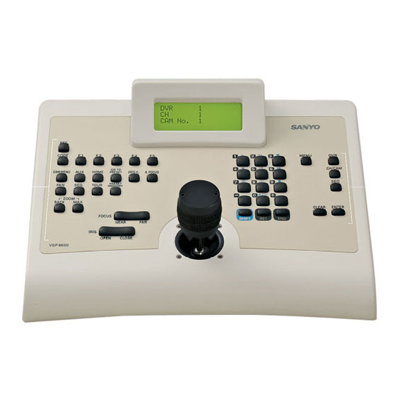
Operating the hard disk digital recorder ■ Address settings When the power is turned on, the initial display appears after the version information automatically displays. SANYO VSP-8500 System Controller ① ② ③ CAM No. ① DVR connection number ② Camera CH connected to the DVR (16ch type: 1-16) Press the DVR button. -
Page 37: Dvr Channel Switching
■ DVR channel switching ① Press the CH/CAM button on the initial display. ② Select the channel (i.e.: 4) using the numeric buttons and press the ENTER button. The monitor switches to the specified channel. CAM No. CAM No. ■ Automatic switching of the image in the monitor When the SEQ button is pressed while configuring the channel settings, “... -
Page 38: Operations From This Unit Using Dvr Operating Buttons
Operating the hard disk digital recorder (continued) ■ Operations from this unit using DVR operating buttons There are two operating methods as follows. Menu display Operations using SHIFT button combinations (P38) Press the 1-0 button while pressing the “SHIFT” button. The command of the pressed button appears at the bottom of the initial display and the operating mode switches to the selected command. -
Page 39: Operations Using Shift Button Combinations
■ Operations using SHIFT button combinations Press the numeric button while pressing the Confirm the operating status on the DVR or monitor screen. PLAY: (Play) Plays back the normal recorded area or alarm recording area. STILL: (Stll) Press this during playback. This pauses the image. -
Page 40: Operations Using Set Button Combinations
Operating the hard disk digital recorder (continued) ■ Operations using SET button combinations Press the numeric button while pressing the Confirm the operating status on the DVR or monitor screen. MONITOR: (Main) Press to operate the main monitor. MONITOR 2: (Monitor 2) The monitor 2 output channel of the DVR can be switched. -
Page 41: Camera Operation
(P24) • Configuring “– – –” as the protocol of Line V LINES SETUP ºLine V Line A Line B • Configuring “Sanyo SSP” as the protocol of Line A LINES SETUP Line V ºLine A Line B LINE V ºProtocol:---... -
Page 42: Operating The Camera From This Unit Using The J Stick And Camera Operating Buttons
AUX 1 ON: This function transmits the ON command to AUX1. For example, if this button is pressed, “AUX 1 ON” displays and in the case of Sanyo’s Day/Night camera, the camera automatically switches to color mode. Operation CAM No. - Page 43 OFF. Enter the numbers while the AUX is ON or OFF and press the ENTER button. Press the ESC button to return to the initial display. (Refer to the Sanyo camera AUX command table. P52) AUXILIARY CONTACT AUX ON : –...
-
Page 44: Operates The Pan, Sequence And Tour Operations Of The Ptz Camera
Camera operation (continued) ■ Operates the pan, sequence and tour operations of the PTZ camera The pan, sequence, and tour operations of the PTZ camera can be operated by selecting the preconfigured positions. These operations are limited to the registered operations of the following models. -
Page 45: Others
Specifications Communication method Keyboard Joystick (J stick) Control terminal RS-232C terminal for PC Dipswitch Communication speed Maximum number of connected equipment Usage conditions Storage conditions Power source (AC adapter) Current consumption Weight Appearance and specifications may be revised without notice. Thank you for your understanding. ■... -
Page 46: Appendix
Appendix ■ Communication table Line V (Video communication) MAIN MENU Language: English ºLines Setup Lines Assignment Protocol Sanyo SSP Line A (Camera communication) MAIN MENU Language: English ºLines Setup Lines Assignment Protocol Video Sanyo SSP SanyoHSSP Macro Ernitec Mark Merc Pelco D Sensorm. -
Page 47: Special Code Table
■ Special code table These functions can be loaded by entering their special codes. ERNITEC SATURN... 46 MARK MERCER ... 47 PELCO... 49 SENSORMATIC ... 51 ¡ERNITEC SATURN Code AUTOPAN Saves the current position of the first limit switch. Saves the current position of the second limit switch. XXX = 0 –... -
Page 48: Mark Mercer
Appendix (Continued) ¡MARK MERCER Code IRIS MANUAL Opens the iris. Closes the iris. ON SCREEN DISPLAY Screen display ON. Screen display OFF. Screen display on top half of monitor. Screen display on bottom half of monitor. INFRARED RESPONSE CURVES Initially set curve (visible light) 950nm curve 850nm curve COLOUR/B&W CAMERA... - Page 49 Code TOGGLE AUTO PARK (ON/OFF) Dome cameras can be set to automatically move to preset position No. 1 after a set stopping interval passes. XX = 01 – 99(*): Waiting time (minutes) before automatically stopping (*) when waiting time XX=00, the function is invalid. Example: “205”...
-
Page 50: Pelco
Appendix (Continued) ¡PELCO Code Pan 0 position SPEED CURVES First speed curve (speed values: 1, 5, 10, 20, 30, 45, 63). Second speed curve (speed values: 1, 10, 20, 30, 40, 50, 63). Third speed curve (speed values: 10, 15, 20, 25, 30, 45, 63). Fourth speed curve (default setting) (speed values: 29, 37, 45, 50, 55, 59, 63). - Page 51 Code ALARMS Alarm identification (X is 1 to 8) MISC Cleans screen. Initializes remote camera operations (pan/tilt). Initializes remote camera operations (to default values). 9999 Backlight compensation ON Backlight compensation OFF White balance ON White balance OFF Makes “unit phase delay mode” valid. X = 1 –...
-
Page 52: Sensormatic
Appendix (Continued) ¡SENSORMATIC Code RELAYS All relays OFF Relay 1 ON Relay 2 ON Relay 3 ON Relay 4 ON Relay 1 and 2 ON Relay 1 and 3 ON Relay 1 and 4 ON Relay 2 and 3 ON Relay 2 and 4 ON Relay 3 and 4 ON Relay 1, 2 and 3 ON... -
Page 53: Sanyo Camera Aux Command Table
■ Sanyo camera AUX command table command Switch to Color Mode Switch to B/W Mode Switch to Day/Night Auto Mode AUTO RETURN Function ON GLOBAL ADDRESS Function ON REMOTE SET – ALARM DISABLE Function ON AUTO PURSUIT Function ON The aforementioned command strings are for the camera VCC-9500, 9600, 9700, and 9800 series. -
Page 54: Camera Key Command Table
Appendix (Continued) ■ Camera key command table ① Sanyo CODE Aux1 On Aux2 On Aux3 On CAM MENU SHIFT + ESC Exit CAM OSD Aux On 1-16 AUX + AUX Aux Off 1-16 HOME Goto Preset 1 !0 GOTO PRESET... - Page 55 ■ Camera key command table ② MarkM CODE Aux1 On Aux2 On Aux3 On CAM MENU SHIFT + ESC Aux On 1-4 AUX + AUX Aux Off 1-4 HOME Goto Preset 1 !0 GOTO PRESET Goto Preset 1-250 IRIS CENTER !2 AUTO FOCUS ON SHIFT + PAN SHIFT + SEQ...
- Page 56 Printed on recycled paper 1AC6P1P3169-- L8CSD/WA (0407KR-VT) SANYO Electric Co., Ltd. Printed in Italy...