
Related Manuals for Hitachi RAC-AJ10PCASV


Summary of Contents for Hitachi RAC-AJ10PCASV
- Page 1 INSTALLATION & OPERATION MANUAL MODEL RAK-AJ10PCASV/RAC-AJ10PCASV RAK-AJ13PCASV/RAC-AJ13PCASV RAK-AJ18PCASV/RAC-AJ18PCASV RAK-AJ24PCASV/RAC-AJ24PCASV HI2022480HA...
-
Page 2: Table Of Contents
Contents Remote controller instructions Safety instructions Preparation before use Safety Precautions Installation instructions Installation diagram Select the installation locations Indoor unit installation Connecting of the cable Wiring diagram Outdoor unit installation Air purging Maintenance Protection Troubleshooting Display introduction Remote controller operating instructions.See"remote controller instructions"... -
Page 3: Remote Controller Instructions
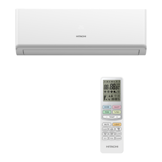
Remote controller Remote controller The remote controller transmits signals to the system. ON/OFF BUTTON The appliance will be started when it is energized or will be stopped when it is in operation, if you press this button. MODE ON/OFF MODE BUTTON Press this button to select the operation mode. - Page 4 Remote controller Remote controller How to Insert the Batteries Remove the battery cover according to the arrow direction. Insert new batteries making sure that the (+) and (-) of battery are matched correctly. Reattach the cover by sliding it back into position. Note: Use 2 LR03 AAA(1.5volt) batteries.
- Page 5 Operation instructions Operation modes Selecting mode Each time the "MODE" button is pressed, the operation mode is changed in sequence: AUTO COOLING FAN ONLY HEATING Heating mode is NOT available for cooling only air conditioner. FAN mode MODE ON/OFF Each time the "FAN" button is pressed, the fan speed is changed in sequence: TURBO Auto...
- Page 6 Operation instructions Airflow direction control Airflow direction control Vertical airflow(Horizontal airflow) is automatically adjusted to a certain angle in accordance with the operation mode after turning on the unit. The direction of airflow can be MODE ON/OFF Operation mode Direction of airflow also adjusted to your own TURBO requirement by pressing the...
- Page 7 Operation instructions CLOCK button You can adjust the real time by pressing CLOCK button, then using “+” and “-” buttons to get the correct time, press CLOCK button again the real time is set. Timer mode It is convenient to set the timer on with TIMER ON button when you go out in the morning to achieve a comfortable room temperature at the time you get home.
- Page 8 Operation instructions SLEEP mode SLEEP mode SLEEP mode can be set in COOLING, HEATING or DRYING operation mode. This function gives you a more comfortable environment for sleep. In SLEEP mode, The appliance will stop operation automatically after operating for 8 hours. Fan speed is automatically set at low speed.
- Page 9 Operation instructions LOCK function LOCK function Press TIME ON and TIME OFF buttons together for 3 seconds to start LOCK function will appears on the the LCD Press TIME ON and TIME OFF buttons together for 3 seconds again to stop LOCK function. will disappeared from the the LCD...
-
Page 10: Safety Instructions
Safety instructions 16. The batteries in remote controller must be recycled or disposed of properly. Disposal of Scrap Batteries --- Please discard the batteries as sorted 1. To guarantee the unit work normally, please read municipal waste at the accessible collection point. the manual carefully before installation, and try to 17. -
Page 11: Safety Precautions
2. Back-light function of Remote Control (optional) Hold down any button on remote control to activate the back light. It automatically shuts off 10 seconds later. Do not use the power Note: Back-light is an optional function. supply circuit breaker Do not touch the or pull off the plug to 3. - Page 12 The following checks shall be applied to 6-3 General work area installations using flammable refrigerants: All maintenance staff and others working in the local area shall be instructed –The charge size is in accordance with the on the nature of work being carried out. Work room size within which the refrigerant in confined spaces shall be avoided.
- Page 13 –Leak detection fluids are suitable for use with This shall include damage to cables, excessive number of connections, terminals most refrigerants but the use of detergents not made to original specification, damage to containing chlorine shall be avoided as the seals, incorrect fitting of glands, etc.
- Page 14 –Cylinders shall be kept upright. 15.Labelling Equipment shall be labelled stating that it has –Ensure that the refrigeration system is earthed been de-commissioned and emptied of prior to charging the system with refrigerant. refrigerant. –Label the system when charging is complete The label shall be dated and signed.
-
Page 15: Installation Instructions
Mechanical connectors used indoors shall Only electric heating to the compressor body comply with ISO 14903. When mechanical shall be employed to accelerate this process. connectors are reused indoors, sealing parts When oil is drained from a system, it shall be shall be renewed. -
Page 16: Select The Installation Locations
Select the installation locations Indoor unit installation Location for Installing Indoor Unit 1. Installing the Mounting Plate Indoor unit Decide an installing location for the mounting plate 1. Where there is no obstacle near Pipe length is 15 meters according to the indoor unit location and pipe the air outlet andair can be easily Max. -
Page 17: Connecting Of The Cable
For ON-OFF appliance Pipe size Torque Nut width Min.thickness Model Pipe Joints Thermal Insulation: φ6mm or 5 12K,13 18K,21 24K Liquid Side ( 1/4 inch) 17mm 0.5mm 15~20N·m Wrap the pipes joints with thermal insulation φ9.53mm or 0.6mm Liquid Side ( 3/8 inch) 18K ,22,24K ,28,30,36K 22mm... -
Page 18: Wiring Diagram
Cable Specifications for Inverter appliance Outdoor unit installation Capacity Power connecting cord Power cord (Btu/h) Normal cross Normal cross 1. Install Drain Port and Drain Hose (for heat-pump Type Type - sectional area - sectional area model only) H07RN-F 0.75~1.5 H05RN-F 0.75mm X4 5K~13K... -
Page 19: Maintenance
How to Purge Air Tubes: Protection (1) Unscrew and remove caps from 2 and 3-way valves. Operating condition (2) Unscrew and remove cap from service valve. Operating temperature for Inverter appliance (3) Connect vacuum pump flexible hose to the service valve. Cooling operation Heating operation Drying operation Temperature... -
Page 20: Troubleshooting
Features of protector Analysis Trouble A sound of flowing water Caused by the flow of refrigerant in the 1. The protective device will work at following cases. air conditioner, not a trouble. Restarting the unit at once after operation stops or Defrosting sound in heating mode. - Page 21 Emergency button Pressing this button can let the AC run or stop The symbol may be different from your model, but the button is similar.
- Page 22 Specifications in this document are subject to change without notice, in order that Hitachi-Johnson Controls Air Conditioning, Inc. may bring the latest innovations to their customers. Hitachi-Johnson Controls Air Conditioning, Inc. © 2022 Hitachi- Johnson Controls Air Conditioning, Inc. 2022.05 Version.A...