Table of Contents
Advertisement
Quick Links
Advertisement
Table of Contents

Related Manuals for bela GLISS

Summary of Contents for bela GLISS
- Page 1 GLISS A touch controller for modular synth User Manual...
-
Page 2: Table Of Contents
GLISS User Manual GLISS User Manual CONTENTS INTRO HELLO GLISS Technical specifications Installation Getting started The faceplates THE INTERFACE The 4 Performance Modes The Menu Global Settings CONTROL The Settings Selectors Selector 1: Control type Selector 2: Latching Input and Outputs... - Page 3 OTHER FUNCTIONS Calibration Mode Reset all menu settings Factory Test Mode Hacking and expanding Gliss Experimental feature: I2C Licensing Updating Gliss firmware Get Support Show us! WARRANTY & COMPLIANCE 3-year warranty A note for Gliss hackers Compliance information CHEAT SHEET...
-
Page 4: Intro
Gliss treads a middle ground between these 2 poles. It offers high-precision touch control that brings physical interaction into your synthesiser setup, but crucially provides a powerfully... - Page 5 CV utility work into an interactive, performative domain. Gliss also packs in a variety of features through its concise Menu system, providing a tuneable 5-key keyboard with glissando and vibrato, 5-step sequencer, waveshaper, wavetable, and much more.
- Page 6 To get the most out of Gliss we recommend you follow this manual step by step with the module in front of you. Gliss has been designed to grow with you over time and has many surprises and hidden talents, which we’ll explain in this guide.
-
Page 7: Hello Gliss
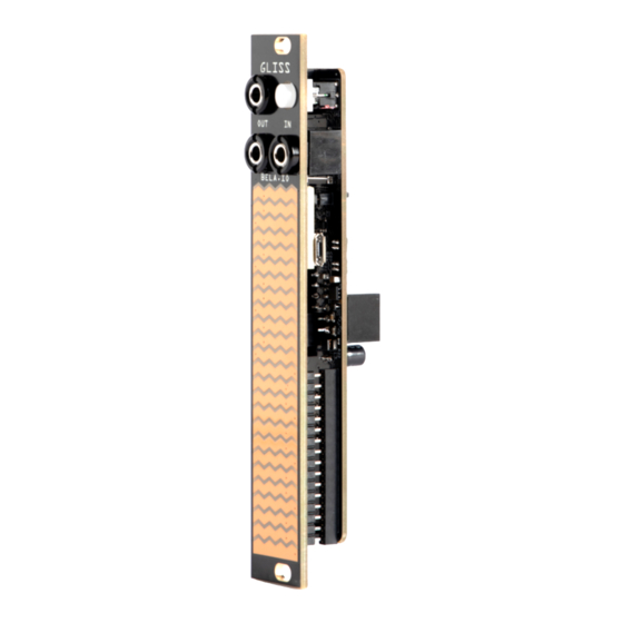
-12V: 30mA Voltage rating: Input and outputs are ±10V safe. Usable range for both input and outputs is -5V to +10V Physical features Gliss has 6 physical features (see diagram): Mounting holes 2. Top Output 3. The Button 4. Bottom Output 5. -
Page 8: Installation
Mode. Control Voltage Outputs Gliss has 2 mono 3.5mm jack outputs - the upper is the Top Output, and below it is the Bottom Output. Both outputs are used to send CV signals, gates, and triggers to other parts of your synth. -
Page 9: Getting Started
To accommodate, we have also included a second faceplate with the jacks and Button at the bottom. If you prefer the jacks and Button at the top, your Gliss comes ready to install. If you want to swap the faceplate, follow the directions below. - Page 10 5. Reattach the jack nuts, reattach Gliss to the power supply and replace the mounting screws. Gliss is now ready to go! You can now install Gliss back in your case, but you’ll have to swap its orientation in the Global Settings menu so everything works as expected (see the Global Settings...
-
Page 11: The Interface
Performance Mode and each of their available settings follows this chapter. The Menu The Menu is the central control interface of Gliss, and is always accessible. In the Menu you can: ● Customise the behaviour of the current Mode by changing the settings (we go into this in detail later in this manual) ●... - Page 12 GLISS User Manual The Interface THE MENU Accessing the Menu You can access the Menu at any time by doing the following: Hold down the Button 2. Tap the Touch Strip with 2 fingers 3. Release the Button To exit the Menu and use your current Mode, tap the Button.
- Page 13 Voltage ranges are a critical aspect of any modular system, as the voltage requirements change across modules, systems, and applications. Gliss comes with all voltage ranges configured to 0 to +10V (the full voltage range is -5V to +10V), but you can configure the voltage ranges for the Input and Outputs individually for each of the 4 Performance Modes.
- Page 14 Mode, and will be remembered when you switch off your module and turn it back on again at a later point. This is to make Gliss as flexible as possible as a performance tool.
- Page 15 For example, 0 to +10V or 0 to +5V is most common for pitch control, but if you’re using Gliss’s output as a source of modulation an output range of -5V to +5V might make more sense, so you can, for example, control pitch bends in both directions around a fixed pitch.
-
Page 16: Global Settings
Module Orientation. 1: Touch Sensitivity As well as sensing touch position, Gliss can sense touch size. Touch size is roughly equal to how hard you press on the Touch Strip. Pressing hard on the strip creates a larger touch size, and pressing lightly creates a touch size that’s very small. - Page 17 4: Module orientation Gliss comes assembled with a faceplate that puts the jacks and button at the top of the module. But, as every synth and setup is different, we included a second faceplate that places the jacks at the bottom.
-
Page 18: Control
GLISS User Manual CONTROL Mode 1: Control signals in real time, with the touch of a finger Control Mode allows you to generate CV signals with the touch of a finger. There are options for combining control via finger position and touch size, or using 2 finger positions or 2 touch sizes. - Page 19 Latching position only can be a useful performance tool. Here’s some ideas for using it: ● Latch position only, leaving touch size unlatched, if you are using Gliss to control the pitch of an oscillator and trigger an envelope. In this case, the touch position CV...
-
Page 20: Input And Outputs
GLISS User Manual Mode 1: CONTROL Unlatched Latched Latch Position MaxV MinV Time Top Output Bottom Output Latching Types This diagram shows the different latching options (Setting Selector 2). The red line shows the value out of the Top Output, and the pink line From left: Unlatched (no held values);... -
Page 21: Record
LFOs and envelopes. In Record Mode you can record custom gestures up to 75 seconds in length. Gliss starts recording your gesture as soon as you place your finger on the Touch Strip, and saves your gesture when you lift it again. -
Page 22: Selector 2: Playback
LFOs. finger on the Touch Strip. When you lift your finger, Gliss will play back the recorded gesture indefinitely. Overwrite your gesture at any time by placing your finger on the Touch Strip and recording a new gesture. - Page 23 GLISS User Manual Mode 2: RECORD Button Press Attack Release Time Recording an Attack/Release envelope with the Button This diagram shows the process of recording an Attack/Release envelope which can be played back with a GATE signal. Draw in the Attack portion of the envelope, then press the Button to indicate the end of Attack and start of Release, then draw in the Release portion of your envelope.
- Page 24 Release section of the envelope starts. If the GATE duration is shorter than the duration of the Attack section, Gliss will just play through the entirety of the Attack and Release sections. The Button can also be used to trigger the playback of Attack/Release envelopes, but note that you need to hold it down to create the sustain, of a GATE signal, instead of tapping it momentarily.
- Page 25 GLISS User Manual Mode 2: RECORD or Dual Touch input (Setting Selector 1), you can record on both halves of the Touch Strip together or separately. (If one half of the Touch Strip is not touched during a recording, nothing will be recorded and any existing recording will persist.) If recorded together, they will have the same loop duration.
- Page 26 To get the most from Wavetable we recommend setting the output range to -5V to +5V. Then the outputs can be treated like audio signals so you can connect Gliss to a Eurorack level mixer directly.
- Page 27 GLISS User Manual Mode 2: RECORD creates square wave-like effects. Your recorded gesture can be updated at any time—just draw in a new pattern on the Touch Strip. You can also use Dual Slider or Dual Touch input and get two simultaneous wavetables.
-
Page 28: Input And Outputs
GLISS User Manual Mode 2: RECORD Input and Outputs Top Output Button Single Slider: Finger position Loop: Trigger, hold to erase Dual Slider: Top finger position Trigger: Trigger gesture, or GATE Dual Touch: Top touch size Clock: Arm recording, press 3... -
Page 29: Signal
GLISS User Manual SIGNAL Mode 3: Clip, scale, offset, smooth, and visualise your signals In Signal Mode, you can visualise and manipulate incoming signals, significantly enhancing the flexibility of your pre-existing modulation sources. Clip, scale, offset, and smooth CV or audio signals, ready to be passed around your system. -
Page 30: Selector 3: Envelope Decay
GLISS User Manual Mode 3: SIGNAL Signal/Envelope detector The Top Output passes the input signal. The Bottom Output passes a scaled ad shifted version of a smoothed envelope of the clipped signal. Envelope detector/inverted envelope detector The Top Output passes the envelope detector, a smoothed signal that rises and falls with the peaks in your input signal. - Page 31 GLISS User Manual Mode 3: SIGNAL Scaled and offset output signal Input signal Scaling and offsetting a CV Signal This diagram Scaled and offset shows a scaled voltage range and offset CV signal. Visualise CV signal Connect a CV signal to the Input, and that input signal will be visualised on the Touch Strip as a moving point, like a very simple oscilloscope.
-
Page 32: Audio Signal Tools
GLISS User Manual Mode 3: SIGNAL Clipped output signal Input signal Clipping CV Signal This diagram shows a clipped CV signal. Note that the output signal is clipped within the range specified on Clipping range the Touch Strip, and then scaled to fill the voltage range. - Page 33 GLISS User Manual Mode 3: SIGNAL Audio Output Line level input Using signal clipping as amplification This diagram shows how clipping can be used as a signal amplifier for weaker signals in your Clipped range of audio input system by setting...
-
Page 34: Input And Outputs
GLISS User Manual Mode 3: SIGNAL Audio Output Audio Input Clipped range of audio input Using signal clipping as distortion [Caption here] Input and Outputs Top Output Button Signal/Signal: Processed output Enter/exit input clipping Signal/ED: Processed output ED/ED: Smoothed envelope... -
Page 35: Notes
If you want your Selector 1: Play mode oscillators to track quantised pitches generated in Notes Mode, be sure to connect Gliss’s Top Output to a VCO’s V/oct input. Selector 2: Quantisation The Settings Selectors... -
Page 36: Selector 2: Quantisation
GLISS User Manual Mode 4: NOTES Sequencer When you’re playing the notes as a Sequencer, the notes are triggered in sequence by an incoming clock signal. Pressing a step will reset the position of the sequencer to that note. Selector 2: Quantisation This setting refers to quantisation while tuning the notes. -
Page 37: Manual Tuning
Gliss responds to very small changes in finger position. To prevent this, press the Button while your finger is still on the Touch Strip. -
Page 38: Keyboard Configuration
Touch Strip to the top. Gliss assumes that pitches are arranged in ascending order up the Touch Strip. For example, this means that when using vibrato, moving your finger up the Touch Strip bends the pitch up, and moving your finger down bends the pitch down. -
Page 39: Sequencer Configuration
Mode 4: NOTES Customise the number of keys Decreasing the number of keys can By default Gliss is configured for a 5-note make the keyboard easier to play, keyboard, but you can choose anywhere and provides more space for between 1 and 5 notes. - Page 40 GLISS User Manual Mode 4: NOTES Choose the next active step While in Active Mode using the Sequencer, you can choose which note is played next on-the-fly by tapping it. That step will be played next, and the sequence will continue looping from that note.
-
Page 41: Input And Outputs
GLISS User Manual Mode 4: NOTES Input and Outputs Top Output Button Keyboard: Pitch of current note Enter/exit Tuning mode Sequencer: Pitch of current note Bottom Output Input Keyboard: Touch size Tuning: Input voltage to be Sequencer: Trigger signal sent... -
Page 42: Other Functions
+5V, and +10V. These voltages are sent out of the Top Output, so you can check those voltage levels if you want to confirm them. You can also check the accuracy of Gliss’s voltage levels by moving your finger up the Touch Strip and evaluating the output. As you move your finger Gliss will output voltages from -5V to +10V, in 1V steps. -
Page 43: Reset All Menu Settings
Menu for Control Mode. Exit the Menu by pressing the Button, and calibration will be saved. Note: If you shut down or power off your Gliss module during calibration, your settings won’t be saved. You can recalibrate Gliss at any time by repeating this process. -
Page 44: Hacking And Expanding Gliss
2 colour states. Press the Button once more to begin the test process. To return to using Gliss, access the Menu (hold the Button, tap the Touch Strip with 2 fingers, and release the Button). Tap the green Mode Selector to tap to the next Mode. -
Page 45: Experimental Feature: I2C
Find all the Gliss hardware and firmware files here: http://github.com/belaPlatform/Gliss You can also find all the Bela repos (for all Bela products, including Trill sensors) on Github: http://github.com/belaPlatform/ Please note: Adding your own hardware or loading your own firmware will void your warranty, as we can only guarantee the features and implementation that we have tested. -
Page 46: Updating Gliss Firmware
Get Support If you run into trouble with Gliss (or any Bela products), the best place to get help is to visit the Bela Forum at http://forum.bela.io. Here you’ll find expert advice from the Bela team, as well as great information from our worldwide community of artists, makers, musicians, and hackers. -
Page 47: Warranty & Compliance
COMPLIANCE 3-year warranty All assembled Gliss modules come with an extended warranty of 3 years from the date of purchase. This warranty covers the failure or malfunction of the device within this period which is due to our manufacturing processes or the components used. The warranty covers return shipping to the customer (worldwide), but not the shipping to have the device returned to Bela.io. -
Page 48: Compliance Information
Gliss is created, designed, and produced by the team at Bela.io. Visit http://bela.io to discover the Bela systems for creating beautiful interaction with sensors and sound, as well as the Trill family of touch sensors that drive Gliss’s touch interaction. -
Page 49: Cheat Sheet
The following 2 pages are a printable Cheat Sheet for quick reference while you’re using Gliss. To create your Gliss Cheat Sheet: Print the pages double-sided, and in the same orientation 2. Crease along the fold lines on the back 3. Fold like a pamphlet, with the Gliss diagram on the cover... - Page 50 Play them back in various The Global Settings menu is for adjusting touch size, or both. ways, as LFOs or envelopes. general behaviours of Gliss. SELECTOR 1: CONTROL TYPE SELECTOR 1: TOUCH INPUT To enter Global Settings: Single Slider...
- Page 51 Mounting Hole Bottom Output Tap to customise the Top Output Input voltage range of the Button Touch Strip Input and Outputs for the current Mode. Gliss comes with 2 faceplates, so you can choose the orientation that’s right for you.
Need help?
Do you have a question about the GLISS and is the answer not in the manual?
Questions and answers