Advertisement
Quick Links
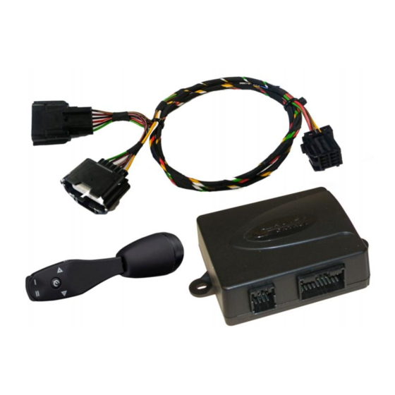
CRUISE CONTROL AP900Ci/ GC90Ci
QUICK INSTALLATION MANUAL
1
CAN-BUS CONNECTION
Engine control
module
T-harness
Accelerator
Model specific T-harness
will be connected between
connectors of accelerator
pedal
If analog inputs activated
connect them like described
on chapter 8 and 9.
Diagnostic
ProTeam OÜ
Männiku tee 104,
11216 Tallinn, Estonia
Tel: +372 672 6308
www.proteam.ee
Control Module (CM)
socket
ORANGE
BLUE
OBD
connector
BLUE/ WHITE
OBD connector is most
common connection point of
CAN-bus wires
By installation refer
connection points
shown on model specific
installation manual
of Beijer Automotive
delivered with the system!
The OBD adapter supplied
with the GC90Ci kit must
not be used. Wires must be
soldered behind the OBD
connector!
Ignition
+12V
CAN High
pos. 6
CAN Low
pos. 14
Advertisement

Summary of Contents for Cruise control AP900Ci
- Page 1 CRUISE CONTROL AP900Ci/ GC90Ci QUICK INSTALLATION MANUAL CAN-BUS CONNECTION Control Module (CM) Engine control module Diagnostic socket Ignition +12V T-harness ORANGE CAN High BLUE pos. 6 Accelerator connector BLUE/ WHITE CAN Low pos. 14 Model specific T-harness will be connected between...
- Page 2 Pedal Learning Mode audible signals clear programing and repeat the test. Sometimes will test pass easier if on step 1 to start the engine. Look software unlock video: AP900Ci/ GC90Ci quick installation manual ProTeam OÜ...
- Page 3 * Pressing the pedal Release BRAKE 95% is easy if to insert Pedal learning Installation is done! a piece of cardboard pedal performed Go to test drive. under the pedal AP900Ci/ GC90Ci quick installation manual ProTeam OÜ...
-
Page 4: Diagnostic Mode
If there no signal use If not check CAN wires or learn speed clutch pedal switch. or use analog speed signal. Switch the ignition completely OFF to Switch the ignition completely OFF to exit Diagnostics exit Diagnostics AP900Ci/ GC90Ci quick installation manual ProTeam OÜ... - Page 5 1 step LONG HIGH HIGH Press and hold Press SET key 4 Release BRAKE- Press briefly Stop safely the BRAKE pedal times setup completed. BRAKE pedal vehicle (lift CM up 4x) AP900Ci/ GC90Ci quick installation manual ProTeam OÜ...
-
Page 6: Gain Adjustment
1 step LONG HIGH HIGH Press briefly Stop safely the Press and hold Press SET key 4 Release BRAKE- BRAKE pedal vehicle BRAKE pedal times setup completed. (lift CM up 4x) AP900Ci/ GC90Ci quick installation manual ProTeam OÜ... - Page 7 SET key once- system will start to Release pedals, switch search next suitable CAN- ignition OFF. software. To complete setup perform Software unlock (Ch. 2) AP900Ci/ GC90Ci quick installation manual ProTeam OÜ...
- Page 8 If speed limiter is in analog mode but it’s needed to activate CAN mode just perform CAN search according chapter 7. When CAN software will be found turns limiter to CAN mode and starts to work without performing “Software unlock”. AP900Ci/ GC90Ci quick installation manual ProTeam OÜ...
-
Page 9: Analog Connections
If on dedicated installation manual is Low signal: 0,7V - 2,0V recommended to use pul-up resistor to boost speed signal connect the resistor between High signal:1,3V - 4,2V Orange and Blue wire. Low signal: 0,6V - 3,5V AP900Ci/ GC90Ci quick installation manual ProTeam OÜ... - Page 10 (lift CM up 4x) Learning of speed signal must be performed in analog mode but with the same procedure is possible to calibrate speed signal also in CAN mode. Procedure Release BRAKE- completed setup completed. AP900Ci/ GC90Ci quick installation manual ProTeam OÜ...
-
Page 11: Error Codes
ERROR CODES The Cruise Control is equipped with an error code generator. In case Cruise Control switches off or does not switches on for an abnormal reason will error code indicated with beeps: Number of Description of error beeps control function is pressed for more than 20 seconds...
Need help?
Do you have a question about the AP900Ci and is the answer not in the manual?
Questions and answers