Table of Contents
Advertisement
Quick Links
Installation, Operating and Service Instructions for
Advantage
AGDV-E
Models:
• AGDV3-EN • AGDV3-EP
• AGDV4-EN • AGDV4-EP
• AGDV5-EN • AGDV5-EP
• AGDV6-EN • AGDV6-EP
Table of Contents
1.
Product Description . . . . . . . . . . . . . . . . . . 4
2. Specifications . . . . . . . . . . . . . . . . . . . . . . . 5
3. Pre-Installation . . . . . . . . . . . . . . . . . . . . . . 6
4. Locating the Boiler . . . . . . . . . . . . . . . . . . . 7
5. Air for Combustion and Ventilation . . . . . . 8
6. Venting . . . . . . . . . . . . . . . . . . . . . . . . . . . . 11
7.
Water Piping . . . . . . . . . . . . . . . . . . . . . . . 22
8. Gas Piping . . . . . . . . . . . . . . . . . . . . . . . . . 26
9. Wiring . . . . . . . . . . . . . . . . . . . . . . . . . . . . 28
10. Start-Up and Checkout . . . . . . . . . . . . . . . 31
11. Operation . . . . . . . . . . . . . . . . . . . . . . . . . . 35
12. Service and Maintenance . . . . . . . . . . . . 37
13. Troubleshooting . . . . . . . . . . . . . . . . . . . . 42
14. Service Parts . . . . . . . . . . . . . . . . . . . . . . . 44
Appendix A . . . . . . . . . . . . . . . . . . . . . . . . 52
Appendix B . . . . . . . . . . . . . . . . . . . . . . . . 57
Appendix C . . . . . . . . . . . . . . . . . . . . . . . . 59
TO THE INSTALLER:
Affix these instructions adjacent to boiler.
Provide model number and serial number when
seeking information and support.
TO THE CONSUMER:
Retain these instructions for future reference.
Contact heating contractor for all issues and support.
Improper installation, adjustment, alteration, service or maintenance can cause property damage, injury, or
loss of life. For assistance or additional information, consult a qualified installer, service agency or the gas
supplier. Read these instructions carefully before installing.
109835-01 - 5/20
Installation, Operating & Service Manual
AGDV-E
Page
!
WARNING
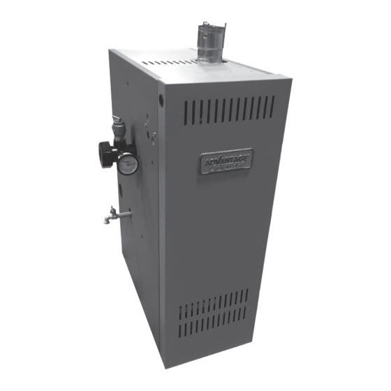
• Water Boiler
• Cast Iron
• Induced Draft
• Gas Fired
9700609
1
Advertisement
Table of Contents

Summary of Contents for Advantage AGDV-E Series
-
Page 1: Table Of Contents
Installation, Operating & Service Manual AGDV-E Installation, Operating and Service Instructions for Advantage • Water Boiler AGDV-E • Cast Iron • Induced Draft • Gas Fired Models: • AGDV3-EN • AGDV3-EP • AGDV4-EN • AGDV4-EP • AGDV5-EN • AGDV5-EP • AGDV6-EN • AGDV6-EP... - Page 2 Installation, Operating & Service Manual AGDV-E The Massachusetts Board of Plumbers and Gas Fitters has approved these boilers. See the Massachusetts Board of Plumbers and Gas Fitters website for the latest Approval Code or ask your local Sales Representative. The Commonwealth of Massachusetts requires this product to be installed by a licensed Plumber or Gas fitter. The following terms are used throughout this manual to bring attention to the presence of hazards of various risk levels, or to important information concerning product life.
- Page 3 Installation, Operating & Service Manual AGDV-E WARNING Asphyxiation Hazard. Fire Hazard. Explosion Hazard. This boiler requires regular maintenance and service to operate safely. Follow the instructions contained in this manual. • Improper installation, adjustment, alteration, service or maintenance can cause property damage, personal injury or loss of life.
-
Page 4: Product Description
Installation, Operating & Service Manual AGDV-E Product Description This is a cast iron gas-fired boiler designed for use in forced hot water heating systems. It is intended for instal- lations where a usable chimney is not available. This boiler is vented using an approved vertical or horizontal AL29-4C stainless steel venting system, which is not included with the boiler. -
Page 5: Specifications
Installation, Operating & Service Manual AGDV-E Specifications Figure 2.1: General Configuration Table 2.2: Specifications AGDV-E Space Heating Ratings Connection Size Direct Vent Approx. ‘A’ Water Shipping Width Content (Supplied Net AHRI Weight Heating Basic with Boiler) Input Rating, AFUE Vent Capacity Boiler Fuel... -
Page 6: Pre-Installation
Installation, Operating & Service Manual AGDV-E Pre-Installation Make sure the boiler is configured for the correct WARNING gas (Natural or LP). Carefully read all instructions before installing G. Do not install this boiler at altitudes above 2000ft. boiler. Failure to follow all instructions in proper H. -
Page 7: Locating The Boiler
Installation, Operating & Service Manual AGDV-E Locating the Boiler Note that if this option is exercised, the relief valve WARNING and gauge must still be installed in the location Failure to observe the following location shown in Figure 4.1. The drain valve on the left requirements could result in a fire, explosion or side of the boiler must also remain accessible. -
Page 8: Air For Combustion And Ventilation
Installation, Operating & Service Manual AGDV-E Locating the Boiler Air for Combustion and Ventilation (continued) Do not install this boiler on carpeting. This may NOTICE: If combustion air is being brought cause a fire. to this boiler using one of the Direct Vent Conversion Kits shown in Table 2.2, requirements G. - Page 9 Installation, Operating & Service Manual AGDV-E Air for Combustion and Ventilation (continued) The National Fuel Gas Code does describe some • If the total volume of both the boiler room other acceptable techniques for bringing outdoor and the room to which the openings combustion air to the boiler room, but these should connect is less than 50 cubic feet per rarely be needed and are not discussed here.
- Page 10 Installation, Operating & Service Manual AGDV-E Air for Combustion and Ventilation (continued) Example: B. Using Outdoor Combustion Air (“Direct Venting”) A 105000 BTU/hr input boiler and a This method requires the Direct Vent Conversion Kit water heater are to be installed in a room shown in Table 2.2.
-
Page 11: Venting
Installation, Operating & Service Manual AGDV-E Venting designed to provide a gas tight seal at all WARNING joints and seams so that flue gas does not Asphyxiation Hazard. Failure to vent this boiler enter the building. Each approved vent in accordance with these instructions could system has unique method for installation - do cause products of combustion to enter the not attempt to mix components from different... - Page 12 Installation, Operating & Service Manual AGDV-E Vent System Design (continued) Table 6.1: Summary Of Venting Options Using Indoor Combustion Air (See Appendix A for Options Using Outdoor Air) Classification Used in this Manual Horizontal Direct Exhaust Vertical Direct Exhaust Vent Option # Illustrated in Figure Structure Penetration Wall...
- Page 13 Installation, Operating & Service Manual AGDV-E Vent System Design (continued) Figure 6.2: Horizontal Direct Exhaust Vent System (Vent Option 1) Figure 6.3: Tee Terminal Figure 6.4: Optional Miter Terminal 109835-01 - 5/20...
- Page 14 Installation, Operating & Service Manual AGDV-E Vent System Design (continued) • The noise level in the vicinity of the 8. Wall Thimbles – Wall thimbles are required terminal is approximately 65 dB (roughly where the vent pipe passes through the level of a normal conversation). Avoid combustible walls with less than the required positioning the terminal in areas where this clearance shown in Figure 4.1 or as required...
- Page 15 Installation, Operating & Service Manual AGDV-E Vent System Design (continued) Figure 6.6: Vertical Direct Exhaust System (Vent Option 2) 109835-01 - 5/20...
- Page 16 Installation, Operating & Service Manual AGDV-E Vent System Design (continued) Table 6.7: Permissible Vent Systems And Principle Vent Components CONDENSATE WALL HORIZONTAL VERTICAL MANUFACTURER VENT SYSTEM SIZE TRAP THIMBLES TERMINATION TERMINATION SAF-T VENT 7393GC 9321 TEE: 7390TEE HEAT FAB EZ SEAL 7393GCS 5300CI (NOTE 2)
- Page 17 Installation, Operating & Service Manual AGDV-E Vent System Design (continued) Figure 6.9a: Location of Vent Terminal Relative to Windows, Doors and Grades Figure 6.9b: Location of Vent Terminal Relative to Meters and Forced Air Inlets 109835-01 - 5/20...
- Page 18 Installation, Operating & Service Manual AGDV-E Vent System Design (continued) Max. Overhang 0 - 12" NOT PERMITTED 12 - 48" 17 - 29" X minus 7" Greater than 48" 17 - 29" 36" Note: Overhang may not be ventilated if 'Y' is less than 48" Figure 6.9c: Location of Vent Terminal Under Overhangs 109835-01 - 5/20...
- Page 19 Installation, Operating & Service Manual AGDV-E Removing Boiler From Common Chimney B. Removing Boiler From Common Chimney of the National Fuel Gas Code, ANSI Z223.1/ NFPA 54 and/or the Natural Gas and Propane When an existing boiler is removed from a Installation Code, CAN/CSA B149.1.
- Page 20 Installation, Operating & Service Manual AGDV-E Removing Boiler From Common Chimney (continued) Une fois qu’il a été déterminé, selon la C. Vent System Assembly méthode indiquée ci-dessus, que chaque 1. General Assembly Notes: appareil raccordé au système a. Where the use of “silicone” is called for in the d’évacuation est mis à...
- Page 21 Installation, Operating & Service Manual AGDV-E Vent System Assembly (continued) d. On the male end of the pipe, apply a ¼” 4. Complete the rest of the vent system in wide bead of high temperature silicone accordance with the vent manufacturer’s approximately ½...
-
Page 22: Water Piping
Installation, Operating & Service Manual AGDV-E Water Piping A. Standard Piping WARNING Figure 7.2 shows typical boiler system • Failure to properly pipe boiler may result in connections on a single zone system. Additional improper operation and damage to boiler or information on hydronic system design may be building. - Page 23 Installation, Operating & Service Manual AGDV-E Water Piping (continued) 6. Low Water Cut-Off (factory supplied) This boiler 7. Manual Reset High Limit (Required by some is equipped with a low water cut-off (LWCO) codes) - This control is required by ASME that prevents the boiler from firing if there is CSD-1 and some other codes.
- Page 24 Installation, Operating & Service Manual AGDV-E Water Piping (continued) 10. Drain Valve - The drain valve is shipped in the 2. Large Water Volume and Low Temperature boiler parts bag. Install it in the 3/4" tapping Systems - Use a system bypass if boiler is to as shown in Figure 7.1.
- Page 25 Installation, Operating & Service Manual AGDV-E Water Piping (continued) If the boiler is to be used in such a system, it WARNING must be separated from the oxygenated water Oxygen contamination of boiler water will cause being heated with a heat exchanger as shown corrosion of iron and steel boiler components in Figure 7.4.
-
Page 26: Gas Piping
Installation, Operating & Service Manual AGDV-E Gas Piping b. Use thread compounds (pipe dope) resistant WARNING to action of liquefied petroleum gas. • Shut off gas supply before servicing the boiler. c. Install sediment trap, ground-joint union and • All gas piping must be gas tight. Use thread manual shut-off valve upstream of boiler gas compound that is listed for gas service on all control valve. - Page 27 Installation, Operating & Service Manual AGDV-E Gas Piping (continued) WARNING • If gas pressure in the building is above ½ psig (3.5 kPa), an additional gas pressure regulator is required. Using one additional regulator for multiple gas appliances may result in unsafe boiler operation.
-
Page 28: Wiring
Installation, Operating & Service Manual AGDV-E Wiring 1. Line Voltage (120 VAC) Field Connections – See WARNING Figure 9.1 for line voltage connections. Provide a • All wiring and grounding must be done in dedicated circuit for the boiler of 15A or greater. accordance with the authority having jurisdiction A service switch is recommended and is required or, in the absence of such requirements, with... - Page 29 Installation, Operating & Service Manual AGDV-E Wiring (continued) Figure 9.1: Line Voltage Connections 24V CH 8.8.8 Thermostat (by others) Hydrostat Temperature Limit/LWCO Green Ground Screw Internal J-Box BL WH Power Overcurrent Service Protection/ Switch Supply Disconnect (optional) 120/60/1 (By Installer) (By Installer) Green Ground Screw...
- Page 30 Installation, Operating & Service Manual AGDV-E Wiring (continued) Power Supply 120/60/1 (By Installer) Overcurrent 24V CH Thermostat Protection/ (by others) Disconnect (By Installer) Hydrostat Service Switch Temperature (optional) Limit/LWCO (By Installer) Internal J-Box On/Off Switch Relay 1 R 1 L2 C2 C1 B1 B2 Internal J-Box...
-
Page 31: Start-Up And Checkout
Installation, Operating & Service Manual AGDV-E Start-up and Checkout H. Adjust thermostat to the highest setting. WARNING Start the boiler using the lighting instructions Do not leave the boiler in service if it fails any shown in Figure 10.2. Upon initial start-up, the gas of the following start-up checks. - Page 32 Installation, Operating & Service Manual AGDV-E Start-up and Checkout (continued) Figure 10.2: Operating Instructions 109835-01 - 5/20...
- Page 33 Installation, Operating & Service Manual AGDV-E Start-up and Checkout (continued) LP Gas Only. The pilot burner produces three 6. Read the manifold pressure. It should be set at: (3) flames. The center flame should be steady, Natural Gas LP Gas medium hard blue enveloping 3/8 to 1/2 inch Manifold Press.
- Page 34 Installation, Operating & Service Manual AGDV-E Start-up and Checkout (continued) Figure 10.4: Main Burner Flame Figure 10.5: Pilot Burner Flame (NG Only) Figure 10.6: Pilot Burner Flame (LP Only) Figure 10.6: Pilot Burner Flame (LP Only) 109835-01 - 5/20...
-
Page 35: Operation
Installation, Operating & Service Manual AGDV-E Operation A. Temperature Limit/LWCO Control Refer to the HydroStat 3200 Installation Instructions and Operating Manual included with these instructions. B. Electronic Ignition Module See Figure 11.1 for electronic ignition (EI). Electronic Ignition Modules with LED indicators. Table 11.2 cross-references the ignition module terminal designations to the ignition terminal numbers in the wiring ladder diagrams. - Page 36 Installation, Operating & Service Manual AGDV-E Operation (continued) i. Restore boiler power at circuit vi. If needed, adjust pilot flame breaker or fuse box. by turning the gas valve pilot ii. Set thermostat to call for heat. adjustment screw clockwise to decrease or counterclockwise to iii.
-
Page 37: Service And Maintenance
Installation, Operating & Service Manual AGDV-E Installation, Operating & Service Manual SERIES 2E Service and Maintenance Service and Maintenance Important Product Safety Information: Refractory Ceramic Fiber Product WARNING Some boiler components use materials that contain refractory ceramic fibers (RCF). RCF has been classified as a possible human carcinogen. When exposed to elevated temperatures, RCF may change into crystalline silica, a known carcinogen. - Page 38 Installation, Operating & Service Manual AGDV-E Service and Maintenance (continued) A. Annual Maintenance WARNING 1. Turn off electrical power and gas supply to the • Label all wires prior to disconnection when boiler. servicing controls. Wiring errors can cause improper and dangerous operation. Verify 2.
- Page 39 Installation, Operating & Service Manual AGDV-E Service and Maintenance (continued) WARNING Soot deposits in the flue passages are a sign that the boiler may be operating at high carbon monoxide (CO) levels. After cleaning the boiler of soot deposits, check the CO level in the flue gas to insure that the boiler is operating properly.
- Page 40 Installation, Operating & Service Manual AGDV-E Service and Maintenance (continued) 11. Clean the flue passageways using a stiff bristle C. Service Notes brush. Be certain that all foreign material is 1. Pressure Switch – This boiler is equipped with a removed from the gaps between the pins.
- Page 41 Installation, Operating & Service Manual AGDV-E Service and Maintenance (continued) Figure 12.3a: Pressure Switch Connections Figure 12.3b: Measuring Pressure Across Pressure Switch 109835-01 - 5/20...
-
Page 42: Troubleshooting
Installation, Operating & Service Manual AGDV-E Troubleshooting A. Before Troubleshooting Refer to the HydroStat 3200 Installation Instructions and Operating Manual included with When troubleshooting the following should be these instructions for additional troubleshooting kept in mind: information. 1. This information is only meant to be used by C. - Page 43 Installation, Operating & Service Manual AGDV-E Troubleshooting (continued) "CALL FOR HEAT." POWER TO CHECK LINE VOLTAGE POWER, LOW VOLTAGE TRANSFORMER, LIMIT CONTROLLER, THERMOSTAT (CONTROLLER), AND WIRING. ALSO, MODULE? (24 V CHECK AIR PROVING SWITCH ON COMBUSTION AIR BLOWER SYSTEM (IF USED) AND THAT THE VENT DAMPER END SWITCH (IF USED) NOMINAL) IS MADE.
-
Page 44: Service Parts
Installation, Operating & Service Manual AGDV-E REV. DATE DESCRIPTION Service Parts All Advantage Repair Parts may be obtained through F.W. Webb Company, 10 Webb Drive, Londonderry, NH 03053 or any other F.W. Webb Company location. Part Number [Quantity] Description 3 Section 4 Section... - Page 45 Installation, Operating & Service Manual AGDV-E Service Parts (continued) WARNING If base must be replaced, there is a good chance pilot assembly and pilot tubing will need to be replaced as well. Replacement pilot assemblies are shown on page 46. Also check condition of manifold and gas valve and replace if they show any signs of heat,...
- Page 46 Installation, Operating & Service Manual AGDV-E Service Parts (continued) Part Number [Quantity] Description 3 Section 4 Section 5 Section 6 Section Gas Valve (Natural Gas), 110404-01 [1] VR8204C6000 Gas Valve (Natural Gas), VR8304P4553 Gas Valve (LP Gas), 110406-01 [1] VR8204C6018 Gas Valve (LP Gas), VR8304P4280 109731-03...
- Page 47 Installation, Operating & Service Manual AGDV-E REVISIONS REV. DATE DESCRIPTION 3/4/2020 INITIAL RELEASE Service Parts (continued) MATERIAL: UNLESS OTHERWISE NOTED: THIRD ANGLE DES: JP SCALE ALL DIMENSIONS IN INCHES. PROJECTION ITEM NUMBER: TOLERANCES: CHK: JP SIZE: C X.X ±.1 X.XXX ±.005 FIRST USE: X.XX ±.03 ANGLE ±1°...
- Page 48 Installation, Operating & Service Manual AGDV-E Service Parts (continued) Part Number [Quantity] Description 3 Section 4 Section 5 Section 6 Section 110402-03 110402-04 110402-05 110402-06 Burner Cover (Natural Gas Only) 109835-01 - 5/20...
- Page 49 Installation, Operating & Service Manual AGDV-E Service Parts (continued) Part Number [Quantity] Key No. Description 3 Section 4 Section 5 Section 6 Section Honeywell S8670E EI Module 100959-01 [1] Honeywell Relay Module 80160096 [1] Hydrostat 3200 w/ Sensor 105161-01 [1] 6D, 4C, Air Pressure Switch w Tubing 110415-01 [1]...
- Page 50 Installation, Operating & Service Manual AGDV-E Service Parts (continued) Part Number [Quantity] Description 3 Section 4 Section 5 Section 6 Section Left Jacket Panel 110622-01 [1] Right Jacket Panel Rear Jacket Panel Vestibule Jacket Panel Top Jacket Panel 110624-03 [1] 110624-04 [1] 110624-05 [1] 110624-06 [1]...
- Page 51 Installation, Operating & Service Manual AGDV-E Service Parts (continued) Part Number [Quantity] Description 3 Section 4 Section 5 Section 6 Section Water Manifold 109614-01 [1] Temperature/Pressure Gauge 105894-01 [1] 3/4" Safety Relief Valve 109038-01 [1] (30 psi) Boiler Drain Valve Obtain Locally (3/4"...
- Page 52 Installation, Operating & Service Manual AGDV-E Appendix A: Direct Vent Installations This Appendix describes how to bring B. Vent System Design and Assembly – combustion air directly from outside to the boiler Vent system is assembled using installer (direct venting) using the Direct Vent Conversion supplied AL29-4C stainless steel vent Kits shown in Table 2.2.
- Page 53 Installation, Operating & Service Manual AGDV-E Appendix A (continued) Table A.2: Summary Of Direct Vent Options (See Section 6 for Additional Details on Vent System Installation) Classification Used in this Manual Horizontal Direct Vent Vertical Direct Vent Vent Option # Illustrated in Figure A.3, A.4 A.3, A.4...
- Page 54 Installation, Operating & Service Manual AGDV-E Appendix A (continued) Figure A.4: Horizontal Direct Venting (Vent Options 5, 6) 3. Permitted Intake Terminals – 4. Horizontal terminal location – Install the intake terminal to either side of the a. Horizontal venting applications use the exhaust terminal as shown in Figure A.4.
- Page 55 Installation, Operating & Service Manual AGDV-E Appendix A (continued) Figure A.5: Horizontal Terminal Offsets Figure A.6: Vertical Direct Vent System (Vent Options 7, 8) 109835-01 - 5/20...
- Page 56 Installation, Operating & Service Manual AGDV-E Appendix A (continued) D. Air Intake System Assembly - 4. If PVC is used for the intake system, the PVC will fit over the outside of the air intake collar 1. If PVC piping is used, use PVC cement to on the boiler.
- Page 57 Installation, Operating & Service Manual AGDV-E Appendix B: Low Return Water Temperatures Thermal Shock: Cast iron boilers are very robust. 110°F and below return water temperatures will not cause thermal shock to our castings. Condensation is a different matter: Cast iron boilers will tolerate intermittent periods of condensation but are not designed for extended condensation periods.
- Page 58 Installation, Operating & Service Manual AGDV-E Appendix B (continued) Primary-Secondary Pumping: This is an improvement over simple by-pass piping to reduce condensation. Again this is a fixed system. It can not adapt to variations in temperature and flow. Best Alternative: F.W. Webb offers a system by-pass kit [part number 107795-01] that addresses these situations.
- Page 59 Installation, Operating & Service Manual AGDV-E Appendix C: Special Requirements For Side-Wall Vented Appliances In The Commonwealth of Massachusetts IMPORTANT The Commonwealth of Massachusetts requires compliance with regulation 248 CMR 4.00 and 5.00 for installation of side-wall vented gas appliances as follows: 1.
- Page 60 Installation, Operating & Service Manual AGDV-E Notes F.W. Webb Company 10 Webb Drive Londonderry, NH 03053 www.fwwebb.com 109835-01 - 5/20...
Need help?
Do you have a question about the AGDV-E Series and is the answer not in the manual?
Questions and answers
Flue intake and exhaust termination kit model number 5 section boiler