H3C S6850 Series Manual
Hide thumbs
Also See for S6850 Series:
- Configuration manual (394 pages) ,
- Installation manual (82 pages) ,
- Troubleshooting manual (58 pages)
Table of Contents
Advertisement
Quick Links
H3C S6850 & S9850 Switch Series
Hardware Information and Specifications
Document version: 6W103-20230926
Copyright © 2023 New H3C Technologies Co., Ltd. All rights reserved.
No part of this manual may be reproduced or transmitted in any form or by any means without prior written consent of
New H3C Technologies Co., Ltd.
Except for the trademarks of New H3C Technologies Co., Ltd., any trademarks that may be mentioned in this document
are the property of their respective owners.
The information in this document is subject to change without notice
Advertisement
Table of Contents

Related Manuals for H3C S6850 Series


Summary of Contents for H3C S6850 Series
- Page 1 No part of this manual may be reproduced or transmitted in any form or by any means without prior written consent of New H3C Technologies Co., Ltd. Except for the trademarks of New H3C Technologies Co., Ltd., any trademarks that may be mentioned in this document are the property of their respective owners.
-
Page 2: Table Of Contents
Contents 1 Product models and technical specifications ············································ 1-3 Product models ··············································································································································· 1-3 Technical specifications ·································································································································· 1-3 2 Chassis views ························································································ 2-12 LS-6850-56HF/LS-6850-56HF-H1/S6850-56HF-SAN ·················································································· 2-12 LS-6850-56HF-H3 ········································································································································· 2-13 S6850-2C ······················································································································································ 2-15 S9850-4C ······················································································································································ 2-16 S9850-32H ···················································································································································· 2-18 3 FRUs ····································································································· 3-20 Power modules ·············································································································································... - Page 3 Power module status LED ····················································································································· 5-52 Fan tray status LED ······························································································································ 5-52 6 Cooling system ······················································································ 6-53...
-
Page 4: Product Models And Technical Specifications
Product models and technical specifications Product models The H3C S6850 & S9850 switch series include the following models: Series Product model Product code • LS-6850-56HF • LS-6850-56HF-H1 S6850-56HF • LS-6850-56HF-H3 H3C S6850 series • LS-6850-56HF-SAN S6850-56HF-SAN • LS-6850-2C S6850-2C •... - Page 5 LS-6850-56HF/LS-6850- Item 56HF-H1/S6850-56HF-S LS-6850-56HF-H3 S6850-2C (H × W × D) 440 × 460 mm (1.72 × 17.32 400 mm (1.73 × 17.32 × 440 × 660 mm (1.74 × 17.32 × 18.11 in) 15.75 in) × 25.98 in) With package: 150 × 718 × With package: 150 ×...
- Page 6 LS-6850-56HF/LS-6850- Item LS-6850-56HF-H3 S6850-2C 56HF-H1/S6850-56HF-S module slots Expansion slots Power module specifications Power input AC input, DC input, and HVDC input Power "Power modules" specifications Power consumption • With two LSWM18CQ modules: 282 W • With two LSWM18CQMSEC modules: 326 W •...
- Page 7 LS-6850-56HF/LS-6850- Item LS-6850-56HF-H3 S6850-2C 56HF-H1/S6850-56HF-S • With two LSWM124XG2QL modules: 337 W • With two LSWM124TG2H modules: 421 W • With two LSWM116FC modules: 385 W Thermal consumption • With two LSWM18CQ modules: 962 BTU/hr • With two LSWM18CQMSEC modules: 1112 BTU/hr •...
- Page 8 LS-6850-56HF/LS-6850- Item 56HF-H1/S6850-56HF-S LS-6850-56HF-H3 S6850-2C LSWM124XG2QL modules: 1150 BTU/hr • With two LSWM124TG2H modules: 1436 BTU/hr • With two LSWM116FC modules: 1314 BTU/hr Heat dissipation Heat dissipation Air cooling method Ventilation Front-to-rear or rear-to-front (based on the installed fan trays) aisles Reliability and availability Power...
- Page 9 Safety standards Product • EMC standards compliance • Environmental and eco-friendly standards Table1-2 H3C S9850 switch series technical specifications Item S9850-4C S9850-32H Physical specifications Without package: 88.1 × 440 × 660 mm Without package: 43.6 × 440 × 460 mm (3.47 ×...
- Page 10 Item S9850-4C S9850-32H Fan tray slots Power module slots Expansion slots Power module specifications Power input AC input, DC input, high-voltage DC input Power "Power modules" specifications Power consumption • With four LSWM18CQ modules: 355 W • With four LSWM18CQMSEC modules: 443 W •...
- Page 11 Item S9850-4C S9850-32H • • With four LSWM18CQMSEC Single DC input: 672 BTU/hr modules: 1512 BTU/hr • Dual DC inputs: 710 BTU/hr • With four LSWM116Q modules: 1061 BTU/hr • With four LSWM18QC modules: 856 BTU/hr • With four LSWM124XG2Q modules: 1239 BTU/hr •...
- Page 12 Item S9850-4C S9850-32H Between Failure (MTBF)(Year) Mean time to repair (MTTR) (Hour) Availability 99.999742% 99.999580% Environment specifications Sound pressure level at 27°C 70.8 dB(A) 62.4 dB(A) (80.6°F) Altitude –60 m to +5000 m (–196.85 ft to +16404.20 ft) 0°C to 45°C (32°F to 113°F) Note: The allowed maximum temperature decreases by 0.33 °C (32.59°F) as the altitude Operating...
-
Page 13: Chassis Views
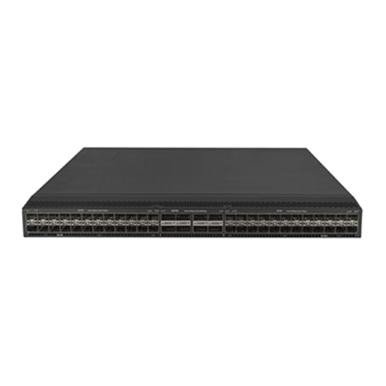
Chassis views LS-6850-56HF/LS-6850-56HF-H1/S6850-56HF- Figure2-1 LS-6850-56HF/LS-6850-56HF-H1/S6850-56HF-SAN front panel (1) 48 × 1GE/10GE/25GE SFP28 Ethernet fiber ports (2) SFP28 port LED (3) 8 × 40GE/100GE QSFP28 Ethernet fiber ports (4) QSFP28 port LED Figure2-2 LS-6850-56HF/LS-6850-56HF-H1/S6850-56HF-SAN rear panel (1) Mini USB console port (2) Copper management Ethernet port (numbered 0) (3) Serial console port (4) USB port... -
Page 14: Ls-6850-56Hf-H3
The LS-6850-56HF, LS-6850-56HF-H1, and S6850-56HF-SAN switches come with the five fan tray slots empty. You must install five fan trays of the same model for the switch. In Figure2-2, five LSWM1FANSA fan trays are installed in the fan tray slots. The LS-6850-56HF, LS-6850-56HF-H1, and S6850-56HF-SAN switches support shipping with fan trays and power modules installed. - Page 15 Figure2-5 LS-6850-56HF-H3 left panel (2) Mounting bracket installation holes at the power (1) Power module latch module side (3) Grounding point 1 (4) Grounding point 2 (5) Mounting bracket installation holes at the port (6) Power module handle side Figure2-6 LS-6850-56HF-H3 rear panel (1) Power module 1 (2) Fan tray 1 (3) Fan tray 2...
-
Page 16: S6850-2C
S6850-2C Figure2-7 S6850-2C front panel (1) Expansion module 1 (2) Expansion module 2 Figure2-8 S6850-2C rear panel (1) Mini USB console port (2) Copper management Ethernet port (numbered 0) (3) Serial console port (4) USB port (5) Two 40GE/100GE QSFP28 Ethernet fiber ports (6) Serial label pull tab (7) Fan tray 1 (8) Fan tray 2... -
Page 17: S9850-4C
Figure2-9 S6850-2C left panel (1) Power module handle (2) Chassis ear position at the power module side (3) Primary grounding point (4) Auxiliary grounding point (5) Chassis ear position at the port side (6) Fan tray handle S9850-4C Figure2-10 S9850-4C front panel (1) Expansion module 1 (2) Expansion module 2 (3) Expansion module 4... - Page 18 Figure2-11 S9850-4C rear panel (1) Mini USB console port (2) Copper management Ethernet port (numbered 0) (3) Serial console port (4) USB port (5) Two 1GE SFP Ethernet fiber ports (6) SFP port LED (7) Fan tray 1 (8) Fan tray 2 (9) Grounding screw (auxiliary grounding point 2) (10) Power module 4 (11) Power module 3...
-
Page 19: S9850-32H
Figure2-12 S9850-4C left panel (1) Fan tray handle (2) Chassis ear position at the power module side (3) Primary grounding point (4) Chassis ear position at the port side (5) Auxiliary grounding point (6) Power module handle S9850-32H Figure2-13 S9850-32H front panel (1) 32 ×... - Page 20 (17) Copper management Ethernet port LED (ACT) (18) System status LED (SYS) (19) Copper management Ethernet port LED (LINK) The ESN serial number and MAC address of the S9850-32H switch can be found on the serial label pull tab. The S9850-32H switch comes with power module slot PWR1 empty and power module slot PWR2 installed with a filler panel.
-
Page 21: Frus
FRUs CAUTION: Do not install fan trays of different models on the same switch. Models that support electronic labels and similar models that do not support electronic labels cannot be installed on the same device, such as the LSWM1FANSA and LSWM1FANSA-SN. The switch uses modular design. - Page 22 LS-6850-5 6HF/LS-68 LS-6850-5 FRUs BOM code 50-56HF-H S6850-2C S9850-4C S9850-32H 6HF-H3 1/S6850-5 6HF-SAN later version • S6850- 56HF-S LSWM1FAN 0231A4BC Yes. • LS-685 0-56HF : in Releas e 6607 later version s and R6555 Yes, in Yes, in Release Release LSWM1FAN installe 6607 and...
- Page 23 LS-6850-5 6HF/LS-68 LS-6850-5 FRUs BOM code 50-56HF-H S6850-2C S9850-4C S9850-32H 6HF-H3 1/S6850-5 6HF-SAN electronic and later label versions. information reading) FAN-40B-1-C 9803A00F FAN-40F-1-D 0231AKLC Expansion modules LSWM18CQ 0231A4XH Yes in Yes in LSWM18CQ E6553 and E6553 and 0231A8FM MSEC later later versions versions...
-
Page 24: Power Modules
The S6850-56HF, S6850-56HF-SAN, S6850-2C, and S9850-32H switches can operate correctly with only one power module. You can install two power modules for 1+1 redundancy. The S9850-4C switch can operate correctly with two power modules. You can install three power modules for 2+1 redundancy or four power modules for 2+2 redundancy. To ensure heat dissipation, make sure all fan slots are installed with fan trays and install fan trays of the same model on the switch as a best practice. - Page 25 (3) AC power receptacle (4) Handle For information about the power module LED, see "Power module LEDs." Features The SW-A-PSR550-12A-B and SW-B-PSR550-12A-B are power modules with AC or HVDC input and DC output. It can provide up to 550 W of output. Table3-2 describes the features provided by the SW-A-PSR550-12A-B and SW-B-PSR550-12A-B power modules.
-
Page 26: 650 W Ac Power Module (Lsvm1Ac650)
650 W AC power module (LSVM1AC650) Figure3-3 LSVM1AC650 power module (1) Latch (2) Power module LED (3) AC power receptacle (4) Handle For information about the power module LED, see "Power module LEDs." Features LSVM1AC650 is a power module with AC input and DC output. It can provide up to 650 W of output. Table3-4 describes the features provided by the LSVM1AC650 power module. -
Page 27: 650 W Dc Power Module (Lsvm1Dc650)
Item Specifications Rated output power 650 W Melting current of power 10 A/ 250 V module fuse 650 W DC power module (LSVM1DC650) Figure3-4 LSVM1DC650 power module (1) Latch (2) Power module LED (3) DC power receptacle (4) Handle For information about the LED, see "Power module LEDs."... -
Page 28: Fan Trays
Item Specifications Rated input current 25 A Rated output current 53 A Rated output voltage 12 V Rated output power 650 W Melting current of power 30 A/ 250 V module fuse Fan trays CAUTION: The switch has multiple fan tray slots. To ensure good ventilation of the switch, follow these guidelines to install and remove fan trays: •... -
Page 29: Lswm1Fansab/Lswm1Fansab-Sn
Features The LSWM1FANSA or LSWM1FANSA-SN fan tray blows air from the power module side to the port side. The fan tray is small, hot swappable, and can automatically adjust the fan speed according to the device temperature. Only the LSWM1FANSA-SN fan tray supports reading the electrical label information. Technical specifications Table3-8 LSWM1FANSA/LSWM1FANSA-SN fan tray specifications Item... -
Page 30: Lswm1Bfansc/Lswm1Bfansc-Sn
Technical specifications Table3-9 LSWM1FANSAB/LSWM1FANSAB-SN fan tray specifications Item Specifications Dimensions (H × W × D) 40.6 × 42.5 × 135.4 mm (1.60 × 1.67 × 5.33 in), including the handle Fans Weight 0.19 kg (0.42 lb) Airflow direction Air exhausted from the fan tray faceplate Max fan speed 21000 R.P.M Max airflow... -
Page 31: Lswm1Bfanscb/Lswm1Bfanscb-Sn
Item Specifications Airflow direction Air drawn in from the fan tray faceplate Max fan speed 13300 R.P.M Max airflow 120 CFM (3.40 m /min) Input voltage 12 V Max power consumption 57 W LSWM1BFANSCB/LSWM1BFANSCB-SN Figure3-8 LSWM1BFANSCB/LSWM1BFANSCB-SN fan tray Handle (red) Alarm LED For information about the LED, see "Fan tray alarm... -
Page 32: Fan-40B-1-C/Fan-40F-1-D
FAN-40B-1-C/FAN-40F-1-D Figure3-9 FAN-40B-1-C/FAN-40F-1-D fan tray For information about the LED, see "Fan tray alarm LEDs." Features The FAN-40B-1-C fan tray draws air from the port side to the power module side. The FAN-40F-1-D fan tray blows air from the power module side to the port side. The fan tray is small, hot swappable, and can automatically adjust the fan speed according to the device temperature. -
Page 33: Lswm18Cq
Interface module Description Interface number and type model MACSec LSWM116Q 16-port QSFP+ interface module 16 × QSFP+ ports LSWM18QC 8-port QSFP+ interface module 8 × QSFP+ ports • 24 × SFP+ ports 24-port SFP+ and 2-port QSFP+ interface LSWM124XG2Q • module with MACSec 2 ×... -
Page 34: Lswm18Cqmsec
LSWM18CQMSEC The LSWM18CQMSEC interface module provides eight QSFP28 ports that all support MACsec. Figure3-11 LSWM18CQMSEC front panel (1) QSFP28 port LED (2) QSFP28 port Ports and LEDs For information about the ports and modules and cables available for the ports, see "QSFP28 port."... -
Page 35: Lswm18Qc
Technical specifications Table3-16 Technical specifications Item Specifications 40.1 × 214 × 274 mm (1.58 × 8.43 × 10.79 in), including the connector but Dimensions (H × W × D) excluding the ejector lever Weight 2 kg (4.41 lb) Power consumption (static) 15 W Power consumption (typical) 37 W... -
Page 36: Lswm124Xgt2Q
Figure3-14 LSWM124XG2Q front panel (1) SFP+ port LED (2) QSFP+ port LED (3) QSFP+ port (4) SFP+ port Ports and LEDs For information about the ports and modules and cables available for the ports, see "SFP+ port" and "QSFP+ port." For information about the LEDs, see "SFP+ port LED"... -
Page 37: Lswm124Xg2Qfc
For information about the LEDs, see "1/10GBase-T autosensing Ethernet port LEDs" and "QSFP+ port LED." Technical specifications Item Specifications 40.1 × 214 × 274 mm (1.58 × 8.43 × 10.79 in), including the connector but Dimensions (H × W × D) excluding the ejector lever Weight 3 kg (6.61 lb) -
Page 38: Lswm124Xg2Ql
LSWM124XG2QL The LSWM124XG2QL interface module provides 24 SFP+ ports and 2 QSFP+ ports. Figure3-17 LSWM124XG2QL front panel (1) SFP+ port LED (2) QSFP+ port LED (3) QSFP+ port (4) SFP+ port Ports and LEDs For information about the ports and modules and cables available for the ports, see "SFP+ port"... -
Page 39: Lswm116Fc
Ports and LEDs For information about the ports and modules and cables available for the ports, see "SFP28 port" "QSFP28 port." For information about the LEDs, see "SFP28 port LED" and "QSFP28 port LED." Technical specifications Table3-21 Technical specifications Item Specifications 40.1 ×... -
Page 40: Ports
As a best practice, use H3C transceiver modules and cables for the switch. H3C transceiver modules and cables are subject to change over time. For the most up-to-date list of H3C transceiver modules and cables, contact H3C Support or marketing staff. For information about the specifications and views of H3C transceiver modules and cables, see H3C Transceiver Modules User Guide. - Page 41 Item Specification • SFP management port: 1000/100 Mbps, full duplex. • 10/100/1000BASE-T management port: 100 m (328.08 ft) over category-5 UTP cable Transmission medium and max • transmission distance SFP management port: See 100-Megabit transceiver modules Table4-3 and Gigabit transceiver modules in Table4-4 Functions and services Software upgrade and network management.
-
Page 42: Usb Port
2.0. NOTE: USB devices from different vendors vary in compatibilities and drivers. H3C does not guarantee correct operation of USB devices from other vendors on the switch. If a USB device fails to operate on the switch, replace it with one from another vendor. -
Page 43: Qsfp+ Port
For more information about the hardware resource flex mode, see device management configuration in H3C S6805 & S6825 & S6850 & S9850 Support for splitting Switch Series Fundamentals Configuration Guide. Only F6633 and later... -
Page 44: Sfp28 Port
NOTE: For information about support for transceiver modules and cables of a QSFP+ port, see H3C S6850 & S9850 Switch Series and Transceivers Compatibility Matrix You can use a QSFP-40G-SR4-MM850 or QSFP-40G-CSR4-MM850 transceiver module to connect a 40G QSFP+ port to four 10G SFP+ ports. The QSFP+... - Page 45 • For more information about SFP28 port configurations, see Ethernet interface configuration in H3C S6805 & S6825 & S6850 & S9850 Switch Series Layer 2—LAN Switching Configuration Guide • S6850-56HF and S6850-56HF-SAN switches support 25G SFP28 transceiver modules/cables, 10G SFP+ transceiver modules/cables, and 1G SFP transceiver modules •...
-
Page 46: Sfp+ Port
NOTE: For information about support for transceiver modules and cables of an SPF+ port, see H3C S6850 & S9850 Switch Series and Transceivers Compatibility Matrix • Installed with an SFP-GE-T or SFP-GE-T-D transceiver module, an SFP+ port can operate only at 1 Gbps •... -
Page 47: Fc Interfaces
A port on an LSWM116FC interface module can operate as an Ethernet interface or FC interface. When it operates as an FC interface, it supports 8G/16G/32G FC modules. For the transceiver modules and cables available for the FC interfaces, see H3C S6850 & S9850 Switch Series and Transceivers Compatibility Matrix. - Page 48 • MDI/MDI-X autosensing • Category-6 UTP cable: 55 m Max transmission • Category-6 STP cable: 100 m distance • Category-6A or above twisted pair cables: 100 m Category 6 or above twisted pair cables. Both straight-through cables and crossover Cables cables are available 4-47...
-
Page 49: Leds
LEDs System status LED The system status LED shows the operating status of the switch. Table5-1 System status LED description LED mark Status Description Steady green The switch is operating correctly. Flashing green The switch is performing power-on self test (POST). Steady red The system POST has failed or a system failure has occurred. -
Page 50: Sfp28 Port Led
LED status Description Flashing green The port is sending or receiving data at 40 Gbps. A transceiver module or cable has been correctly installed. The port has a link Steady yellow and is operating at 10 Gbps. Flashing yellow The port is sending or receiving data at 10 Gbps. No transceiver module or cable has been installed or no link is present on the port. -
Page 51: Sfp Port Led
Flashing yellow The port is sending or receiving data at 1 Gbps. No link is present on the port. SFP port LED Table5-7 SFP port LED description LED status Description A transceiver module or cable has been correctly installed. The port has a link and Steady green is operating at 1 Gbps. -
Page 52: Power Module Leds
Table5-10 Copper management Ethernet port LED description for the LS-6850-56HF-H3 switch LED mark Status Description Steady green The port is operating at 10/100/1000 Mbps. Steady green and LINK/ACT The port is receiving or sending data. flashing yellow No link is present on the port Power module LEDs The LSVM1AC650, LSVM1DC650, SW-A-PSR550-12A-B, and SW-B-PSR550-12A-B power modules each provide a power module LED on the panel to show the power input status and power... -
Page 53: Fan Tray Alarm Leds
LED status Description cord connection or power source shutdown. Fan tray alarm LEDs Each fan tray provides an alarm LED. Table5-14 shows the description for the alarm LEDs on the FAN-40B-1-C or FAN-40F-1-D fan tray. For the description of the alarm LEDs on other fan trays, see Table5-13. - Page 54 Cooling system CAUTION: The chassis and power modules use separate air aisles. Make sure the two aisles are not blocked when the switch is operating. To dissipate heat timely and ensure system stability, the switch uses the front-rear air aisle cooling system.
Need help?
Do you have a question about the S6850 Series and is the answer not in the manual?
Questions and answers