
Related Manuals for Dell OptiPlex Tower 7010


Summary of Contents for Dell OptiPlex Tower 7010
- Page 1 OptiPlex Tower 7010 Owner's Manual Regulatory Model: D32M Regulatory Type: D32M002 March 2023 Rev. A00...
- Page 2 A WARNING indicates a potential for property damage, personal injury, or death. © 2021-2023 Dell Inc. or its subsidiaries. All rights reserved. Dell Technologies, Dell, and other trademarks are trademarks of Dell Inc. or its subsidiaries. Other trademarks may be trademarks of their respective owners.
-
Page 3: Table Of Contents
Contents Chapter 1: Views of OptiPlex Tower 7010..................6 Display.....................................7 Back......................................9 Chapter 2: Set up your computer....................11 Chapter 3: Specifications of OptiPlex Tower 7010................ 17 Dimensions and weight..............................17 Processor..................................... 17 Chipset....................................19 Operating system................................19 Memory....................................19 Memory matrix................................20 External ports..................................20 Internal slots.................................. - Page 4 Removing the side cover............................35 Installing the side cover............................. 37 Front bezel ..................................39 Removing the front bezel............................39 Installing the front bezel............................40 Hard drive.................................... 41 2.5-inch hard drive...............................41 3.5-inch hard drive..............................46 Optical drive..................................48 Removing the Slim optical drive..........................48 Installing the Slim optical drive..........................49 Memory....................................50 Removing the memory...............................
- Page 5 Deleting or changing an existing system setup password................119 Clearing CMOS settings..............................119 Clearing BIOS (System Setup) and System passwords..................119 Chapter 9: Troubleshooting....................... 120 Dell SupportAssist Pre-boot System Performance Check diagnostics.............. 120 Running the SupportAssist Pre-Boot System Performance Check.............. 120 Power-Supply Unit Built-in Self-Test ........................120 System-diagnostic lights..............................121 Recovering the operating system..........................122...
-
Page 6: Chapter 1: Views Of Optiplex Tower 7010
Views of OptiPlex Tower 7010... -
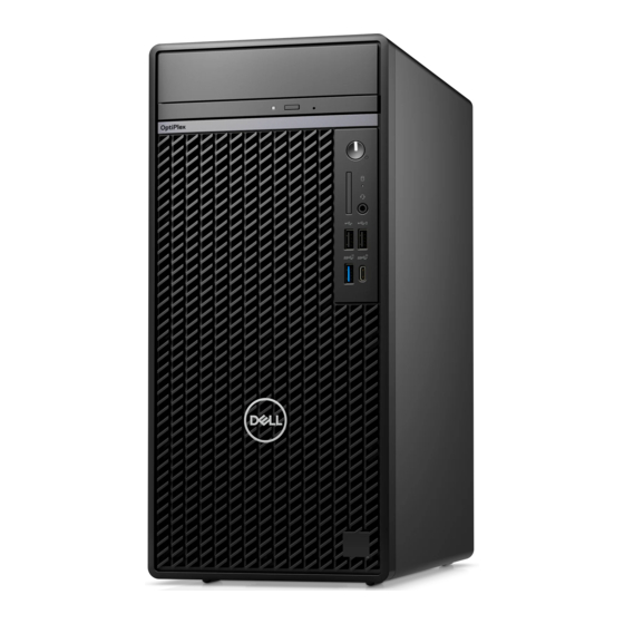
Page 7: Display
Views of OptiPlex Tower 7010 Display Views of OptiPlex Tower 7010... - Page 8 1. Optical disk-drive (optional) 2. Power button with diagnostic LED 3. Hard-drive activity light 4. Universal audio jack port 5. Two USB 2.0 (480 Mbps) ports 6. Two USB 3.2 Gen 1 (5 Gbps) ports Views of OptiPlex Tower 7010...
-
Page 9: Back
Back Views of OptiPlex Tower 7010... - Page 10 13. One video port (DisplayPort 1.4a (HBR3)/HDMI 2.1/VGA) (optional) NOTE: Maximum resolution ● HDMI 2.1: up to 4096 x 2160 @60Hz ● DisplayPort 1.4a (HBR3): up to 5120 x 3200 @60Hz ● VGA: up to 1920 x 1200 @60Hz Views of OptiPlex Tower 7010...
-
Page 11: Chapter 2: Set Up Your Computer
Set up your computer Steps 1. Connect the keyboard and mouse. Set up your computer... - Page 12 2. Connect to your network using a cable. NOTE: Alternatively, you can connect to a wireless network. 3. Connect the display. Set up your computer...
- Page 13 NOTE: If you ordered your computer with a discrete graphics card, the HDMI and the display ports on the back panel of your computer are covered. Connect the display to the port on the discrete graphics card. 4. Connect the power cable. Set up your computer...
- Page 14 5. Press the power button. Set up your computer...
- Page 15 6. Finish the Windows setup. Follow the on-screen instructions to complete the setup. When setting up, Dell recommends that you: ● Connect to a network for Windows updates. NOTE: If connecting to a secured wireless network, enter the password for the wireless network access when prompted.
- Page 16 This software delivers intelligent features that automatically fine-tune your computer for the best possible audio, power, and performance. Get the most out of your Dell device with intelligent, personalized technology from MyDell. Following are the key features of MyDell: ●...
-
Page 17: Chapter 3: Specifications Of Optiplex Tower 7010
Specifications of OptiPlex Tower 7010 Dimensions and weight The following table lists the height, width, depth, and weight of your OptiPlex Tower 7010. Table 2. Dimensions and weight Description Values Height 324.30 mm (12.77 in.) Width 154.00 mm (6.06 in.) Depth 292.20 mm (11.50 in.) - Page 18 20 MB 24 MB 24 MB 4 MB 6 MB Integrated Intel UHD Intel UHD Intel UHD Intel UHD Intel UHD Intel UHD graphics Graphics 730 Graphics 730 Graphics 770 Graphics 770 Graphics 710 Graphics 710 Specifications of OptiPlex Tower 7010...
-
Page 19: Chipset
Chipset The following table lists the details of the chipset supported by your OptiPlex Tower 7010. Table 4. Chipset Description Values Chipset Intel Q670 Processor ● 13 Generation Intel Core i3/i5 ● Intel Pentium Gold ● Intel Celeron DRAM bus width... -
Page 20: Memory Matrix
● 32 GB, 2 x 16 GB, DDR4, 3200 MHz, dual-channel ● 64 GB, 2 x 32 GB, DDR4, 3200 MHz, dual-channel Memory matrix The following table lists the memory configurations supported on your OptiPlex Tower 7010. Table 6. Memory matrix Configuration... -
Page 21: Internal Slots
To learn more about the features of different types of M.2 cards, search in the Knowledge Base Resource at www.dell.com/support. Ethernet The following table lists the wired Ethernet Local Area Network (LAN) specifications of your OptiPlex Tower 7010. Table 9. Ethernet specifications Description Values... -
Page 22: Wireless Module
Wireless module The following table lists the Wireless Local Area Network (WLAN) module specifications of your OptiPlex Tower 7010. Table 10. Wireless module specifications Description Option one Option two Option three Model number Intel AX211 Realtek RTL8852BE Realtek RTL8821CE NOTE:... -
Page 23: Storage
Peak speaker output 2.5 W Subwoofer output Not supported Microphone Supported via Universal audio jack Storage This section lists the storage options on your OptiPlex Tower 7010. Table 12. Storage Matrix Storage 1st 2.5-inch 2nd 2.5- Single 3.5- Single M.2... -
Page 24: Power Ratings
Storage -40°C-70°C (-40°F-158°F) -40°C-70°C (-40°F-158°F) Power supply connector The following table lists the Power supply connector specifications of your OptiPlex Tower 7010. Table 15. Power supply connector 180 W (80 PLUS Bronze) ● Two 4 pin connectors for processor ● One 8 pin connector for system board 300 W (80 PLUS Platinum) ●... -
Page 25: Gpu-Discrete
AMD Radeon RX6500 Two DisplayPort 1.4 ports 4 GB GDDR6 Video port resolution The following table lists the video port resolution for your OptiPlex Tower 7010. Table 18. Video port resolution Graphics card Video ports Maximum supported resolution AMD Radeon RX6300 ●... -
Page 26: Environmental
Trusted Platform Module TPM 2.0 China TPM Intel Secure Boot Intel Authenticate SafeBIOS: includes Dell Off-host BIOS Verification, BIOS Resilience, BIOS Recovery, and additional BIOS Controls Environmental The following table lists the environmental specifications of your OptiPlex Tower 7010. Table 20. Environmental... -
Page 27: Regulatory Compliance
Product Safety, EMC and Environmental Datasheets Dell Regulatory Compliance Home page Dell and the Environment Operating and storage environment This table lists the operating and storage specifications of your OptiPlex Tower 7010. Airborne contaminant level: G1 as defined by ISA-S71.04-1985 Table 22. Computer environment Description... -
Page 28: Chapter 4: Working Inside Your Computer
You should only perform troubleshooting and repairs as authorized or directed by the Dell technical assistance team. Damage due to servicing that is not authorized by Dell is not covered by your warranty. See the safety instructions that is shipped with the product or at www.dell.com/regulatory_compliance. -
Page 29: Safety Precautions
ESD protection is an increasing concern. Due to the increased density of semiconductors used in recent Dell products, the sensitivity to static damage is now higher than in previous Dell products. For this reason, some previously approved methods of handling parts are no longer applicable. -
Page 30: Esd Field Service Kit
Always place parts in your hand, on the ESD mat, in the system, or inside an anti-static bag. ● Transporting Sensitive Components – When transporting ESD sensitive components such as replacement parts or parts to be returned to Dell, it is critical to place these parts in anti-static bags for safe transport. Working inside your computer... -
Page 31: Transporting Sensitive Components
Transporting sensitive components When transporting ESD sensitive components such as replacement parts or parts to be returned to Dell, it is critical to place these parts in anti-static bags for safe transport. -
Page 32: Screw List
● Phillips screwdriver #0 ● Phillips screwdriver #1 ● Plastic scribe Screw list NOTE: When removing screws from a component, it is recommended to note the screw type, the quantity of screws, and then place them in a screw storage box. This is to ensure that the correct number of screws and correct screw type is restored when the component is replaced. -
Page 33: Major Components Of Optiplex Tower 7010
System board #6-32 6-32 6-32 Major components of OptiPlex Tower 7010 The following image shows the major components of OptiPlex Tower 7010. 1. Side cover 2. 3.5-inch hard-disk drive 3. Slim ODD 4. Heat sink and fan assembly 5. Processor 6. - Page 34 18. 2.5-inch hard-disk drive NOTE: Dell provides a list of components and their part numbers for the original system configuration purchased. These parts are available according to warranty coverages purchased by the customer. Contact your Dell sales representative for purchase options.
-
Page 35: Chapter 5: Removing And Installing Customer Replaceable Units (Crus)
Removing and installing Customer Replaceable Units (CRUs) The replaceable components in this chapter are Customer Replaceable Units (CRUs). CAUTION: Customers can replace only the Customer Replaceable Units (CRUs) following the safety precautions and replacement procedures. NOTE: The images in this document may differ from your computer depending on the configuration you ordered. Side cover Removing the side cover Prerequisites... - Page 36 Removing and installing Customer Replaceable Units (CRUs)
-
Page 37: Installing The Side Cover
Steps 1. Loosen the two thumbscrews that secure the side cover to the computer. 2. Slide the side cover towards the rear of the computer and lift the side cover away from the chassis. Installing the side cover Prerequisites If you are replacing a component, remove the existing component before performing the installation procedure. About this task The following image indicates the location of the side cover and provides a visual representation of the installation procedure. - Page 38 Removing and installing Customer Replaceable Units (CRUs)
-
Page 39: Front Bezel
Steps 1. Align the tabs on the side cover with the slots on the chassis. 2. Slide the side cover towards the front of the computer to install it. 3. Tighten the two thumbscrews to secure the side cover to the chassis. Next steps 1. -
Page 40: Installing The Front Bezel
Steps 1. Pry the retention tabs to release the front bezel from the computer. 2. Slightly pull the front bezel and gently rotate to release the other tabs on the bezel from the slots in the computer chassis. 3. Remove the front bezel from the computer. Installing the front bezel Prerequisites If you are replacing a component, remove the existing component before performing the installation procedure. -
Page 41: Hard Drive
Steps 1. Position the front bezel to align the tabs on the bezel with the slots on the chassis. 2. Press the bezel until the tabs clicks into place. Next steps 1. Install the side cover. 2. Follow the procedure in after working inside your computer. - Page 42 About this task The following images indicate the location of the 2.5-inch hard drive assembly and provide a visual representation of the removal procedure. Steps 1. Disconnect the hard drive data and power cables from the connectors on the 2.5-inch hard drive module. 2.
- Page 43 About this task The following images indicate the location of the hard drive bracket and provide a visual representation of the removal procedure. Steps 1. Remove the two (M3x3.5) screws that secure the first hard drive to hard drive cage. 2.
- Page 44 About this task The following image indicates the location of the 2.5-inch hard drive bracket and provides a visual representation of the installation procedure. Steps 1. Align and place the second hard drive into the hard drive cage. 2. Replace the two (M3x3.5) screws to secure the second hard drive to the hard drive cage. 3.
- Page 45 Installing the 2.5-inch hard drive assembly Prerequisites If you are replacing a component, remove the existing component before performing the installation procedure. About this task The following image indicates the location of the 2.5-inch hard drive assembly and provides a visual representation of the installation procedure.
-
Page 46: 3.5-Inch Hard Drive
3.5-inch hard drive Removing the 3.5-inch hard drive assembly Prerequisites 1. Follow the procedure in before working inside your computer. 2. Remove the side cover. 3. Remove the front bezel. About this task The following images indicate the location of the 3.5-inch hard drive assembly and provide a visual representation of the removal procedure. - Page 47 Installing the 3.5-inch hard drive assembly Prerequisites If you are replacing a component, remove the existing component before performing the installation procedure. About this task The following image indicates the location of the 3.5-inch hard drive assembly and provides a visual representation of the installation procedure.
-
Page 48: Optical Drive
Optical drive Removing the Slim optical drive Prerequisites 1. Follow the procedure in before working inside your computer. 2. Remove the side cover. About this task The following images indicate the location of the slim ODD and provide a visual representation of the removal procedure. Steps 1. -
Page 49: Installing The Slim Optical Drive
Installing the Slim optical drive Prerequisites If you are replacing a component, remove the existing component before performing the installation procedure. About this task The following images indicate the location of the slim ODD and provide a visual representation of the installation procedure. Steps 1. -
Page 50: Memory
Memory Removing the memory Prerequisites 1. Follow the procedure in before working inside your computer. 2. Remove the side cover. About this task The following images indicate the location of the memory module and provide a visual representation of the removal procedure. Steps 1. -
Page 51: Solid-State Drives
Steps 1. Align the notch on the memory module with the tab on the memory-module slot. 2. Slide the memory module firmly into the slot and press the memory module down until it clicks into place. NOTE: If you do not hear the click, remove the memory module and reinstall it. Next steps 1. - Page 52 Steps 1. Remove the screw (M2x3.5) that secures the M.2230 solid-state drive to the system board. 2. Slide and lift the M.2230 solid-state drive from the M.2 card slot on the system board. Installing the M.2230 solid-state drives Prerequisites If you are replacing a component, remove the existing component before performing the installation procedure. About this task The following images indicate the location of the M.2230 solid-state drives and provides a visual representation of the installation procedure.
-
Page 53: Solid-State Drive (Full-Length)
Steps 1. Align the notch on the M.2230 solid-state drive with the tab on the M.2 card slot on the system board. 2. Slide the M.2230 solid-state drive into the M.2 card slot on the system board. 3. Replace the screw (M2x3.5) that secures the M.2230 solid-state drive to the system board. Next steps 1. - Page 54 Steps 1. Remove the screw (M2x3.5) that secures the M.2280 solid-state drive to the system board. 2. Slide and lift the M.2280 solid-state drive from the M.2 card slot on the system board. Installing the M.2280 solid-state drive Prerequisites If you are replacing a component, remove the existing component before performing the installation procedure. About this task The following images indicate the location of the M.2280 solid-state drive and provides a visual representation of the installation procedure.
-
Page 55: Wireless Card
Steps 1. Align the notch on the M.2280 solid-state drive with the tab on the M.2 card slot on the system board. 2. Slide the M.2280 solid-state drive into the M.2 card slot on the system board. 3. Replace the screw (M2x3.5) that secures the M.2280 solid-state drive to the system board. Next steps 1. -
Page 56: Installing The Wlan Card
Steps 1. Remove the (M2x3.5) screw that secures the WLAN card to the system board. 2. Lift the WLAN card bracket away from the WLAN card. 3. Disconnect the antenna cables from the WLAN card. 4. Slide and remove the WLAN card from the connector on the system board. Installing the WLAN card Prerequisites If you are replacing a component, remove the existing component before performing the installation procedure. - Page 57 Steps 1. Connect the antenna cables to the WLAN card. The following table provides the antenna-cable color scheme for the WLAN card of your computer. Table 24. Antenna-cable color scheme Connectors on the wireless card Antenna-cable color Main (white triangle) White Auxiliary (black triangle) Black...
-
Page 58: Expansion Card
Expansion card Removing the graphics card Prerequisites 1. Follow the procedure in Before working inside your computer. 2. Remove the side cover. About this task The following images indicate the location of the graphics card and provides a visual representation of the removal procedure. Steps 1. -
Page 59: Installing The Graphics Card
Installing the graphics card Prerequisites If you are replacing a component, remove the existing component before performing the installation procedure. About this task The following images indicate the location of the graphics card and provides a visual representation of the installation procedure. Steps 1. -
Page 60: Internal Speaker
Internal speaker Removing the speaker Prerequisites 1. Follow the procedure in Before working inside your computer. 2. Remove the side cover. About this task The following images indicate the location of the speaker and provides a visual representation of the removal procedure. Steps 1. -
Page 61: Coin-Cell Battery
Steps 1. Press the tab on the speaker and slide the speaker into the slot on the chassis until it snaps into place. 2. Press down on the speaker to secure the speaker with the tab on the chassis. 3. Route the speaker cable through the routing guide on the chassis. 4. -
Page 62: Installing The Coin-Cell Battery
Steps 1. Push the coin-cell battery-release lever on the coin-cell battery socket to release the coin-cell battery out of the socket. 2. Remove the coin-cell battery. Installing the coin-cell battery Prerequisites If you are replacing a component, remove the existing component before performing the installation procedure. About this task The following images indicate the location of the speaker and provides a visual representation of the installation procedure. - Page 63 Steps Insert the coin-cell battery into the socket with the positive side (+) label facing up and snap the battery in the socket. Next steps 1. Install the side cover. 2. Follow the procedure in After working inside your computer. Removing and installing Customer Replaceable Units (CRUs)
-
Page 64: Chapter 6: Removing And Installing Field Replaceable Units (Frus)
To avoid any potential damage to the component or loss of data, ensure that an authorized service technician replaces the Field Replaceable Units (FRUs). CAUTION: Dell Technologies recommends that this set of repairs, if needed, to be conducted by trained technical repair specialists. CAUTION: As a reminder, your warranty does not cover damages that may occur during the courses of FRU repairs that are not authorized by Dell Technologies. -
Page 65: Installing The Intrusion Switch
Steps 1. Disconnect the intruder cable from the connector on the system board. 2. Unhook the intruder cable from the retention clip. 3. Slide and remove the intrusion switch from the chassis. Installing the intrusion switch Prerequisites If you are replacing a component, remove the existing component before performing the installation procedure. About this task The following image indicates the location of the intrusion switch and provides a visual representation of the installation procedure. -
Page 66: Power-Supply Unit
Steps 1. Insert the intrusion switch into its slot and slide the switch to secure it into the slot. 2. Route the intruder cable through the retention clip. 3. Connect the intruder cable to the connector on the system board. Next steps 1. - Page 67 Removing and installing Field Replaceable Units (FRUs)
-
Page 68: Installing The Power-Supply Unit
Steps 1. Disconnect the power-supply cables from their connectors on the system board. 2. Remove the power-supply cables from the routing guides on the chassis. 3. Remove the three screws (#6-32) that secure the power-supply unit to the chassis. 4. Slide and lift the power-supply unit off the chassis. Installing the power-supply unit CAUTION: The information in this section is intended for authorized service technicians only. - Page 69 Removing and installing Field Replaceable Units (FRUs)
-
Page 70: Processor Fan And Heat-Sink Assembly
Steps 1. Place the power-supply unit on the chassis and slide it towards the back of the chassis. 2. Replace the three (#6-32) screws to secure the power-supply unit to the chassis. 3. Route the power-supply cables through their routing guides on the chassis. 4. -
Page 71: Installing The Processor Fan And Heat-Sink Assembly
WARNING: The heat sink may become hot during normal operation. Allow sufficient time for the heat sink to cool before you touch it. CAUTION: For maximum cooling of the processor, do not touch the heat transfer areas on the heat sink. The oils in your skin can reduce the heat transfer capability of the thermal grease. - Page 72 About this task The following image indicates the location of the processor fan and heat-sink and provides a visual representation of the installation procedure. Steps 1. Align the screws on the processor fan and heat-sink assembly with the screw holders on the system board and place the processor fan and heat-sink assembly on the processor.
-
Page 73: Fan Shroud
Fan shroud Removing the fan duct Prerequisites 1. Follow the procedure in before working inside your computer. 2. Remove the side cover. About this task The following images indicate the location of the fan duct and provide a visual representation of the removal procedure. Steps 1. -
Page 74: Installing The Fan Duct
Installing the fan duct Prerequisites If you are replacing a component, remove the existing component before performing the installation procedure. About this task The following image indicates the location of the fan duct and provides a visual representation of the installation procedure. Steps 1. -
Page 75: Processor
Processor Removing the processor Prerequisites 1. Follow the procedure in before working inside your computer. 2. Remove the side cover. 3. Remove the duct. 4. Remove the processor fan and heat-sink assembly. NOTE: The processor might still be hot after the computer is shut down. Allow the processor to cool down before removing About this task The following images indicate the location of the processor and provide a visual representation of the removal procedure. -
Page 76: Power Button
Steps 1. Ensure that the release lever on the processor socket is fully extended in the open position. 2. Align the notches on the processor with the tabs on the processor socket and place the processor in the processor socket. NOTE: The pin-1 corner of the processor has a triangle that aligns with the triangle on the pin-1 corner on the processor socket. -
Page 77: Installing The Power Button
Steps 1. Disconnect the power-button cable from the connector on the system board. 2. Press the release tabs on the power-button head and slide the power-button cable out from the front-side chassis of the computer. 3. Pull the power-button cable out from the computer. Installing the power button Prerequisites If you are replacing a component, remove the existing component before performing the installation procedure. -
Page 78: Wireless Antenna Kit
Steps 1. Insert the power-button cable into the slot from the front-side of the computer, and press the power-button head until it clicks into the place in the chassis. 2. Align and connect the power-button cable to the connector on the system board. Next steps 1. - Page 79 Removing and installing Field Replaceable Units (FRUs)
- Page 80 Steps 1. Remove the (M2x3.5) screw that secures the wireless card bracket to the system board. 2. Slide and lift the wireless card bracket away from the wireless card. 3. Disconnect the antenna cables from the connectors on the wireless card. 4.
- Page 81 Steps 1. Peel away the protective tape from the back of the antennas. 2. Insert the antennas into the slots on the chassis. The antennas should be installed on the appropriate slots on the chassis. The following table provides guidance on the correct installation method.
-
Page 82: External Sma Antenna Kit
Next steps 1. Install the front bezel. 2. Install the side cover. 3. Follow the procedure in after working inside your computer. External SMA antenna kit Removing optional SMA module Prerequisites 1. Follow the procedure in before working inside your computer. - Page 83 Steps 1. Open cable holder and unroute the SMA module cable from the cable holder on the chassis. 2. Lift the pull tab to open the PCIe door. 3. Hold and remove the SMA module from its connector on the system board. Installing optional SMA module Prerequisites If you are replacing a component, remove the existing component before performing the installation procedure.
- Page 84 Removing and installing Field Replaceable Units (FRUs)
- Page 85 Steps 1. To remove the PCIe dummy bracket, insert a flat-head screwdriver in the hole of the bracket, push the bracket to release it, and then lift the bracket out of the system. 2. Lift the pull tab to open the PCIe door. 3.
-
Page 86: Optional Input/Output Modules
Optional Input/Output modules Serial module Removing the optional serial module Prerequisites 1. Follow the procedure in Before working inside your computer. 2. Remove the side cover. About this task The following images indicate the location of the optional serial module and provides a visual representation of the removal procedure. -
Page 87: Vga Module
Steps 1. Using a screwdriver, remove the serial module cover from the chassis. NOTE: This step is applicable only when the serial module is being installed for the first time. 2. Connect the serial-module cable to the connector (KB_MS_SERIAL) on the system board 3. - Page 88 About this task The following images indicate the location of the optional VGA module and provide a visual representation of the removal procedure. Steps 1. Remove the two (4-40x6.5) screws that secure the optional VGA module to the computer chassis. 2.
-
Page 89: Dp Module
Steps 1. To remove the dummy metal bracket, insert a star-head screwdriver in the hole of the bracket, push the bracket to release the bracket, and then lift the bracket out from the system. NOTE: Applies if you are upgrading the system that did not have these optional modules. 2. - Page 90 About this task The following images indicate the location of the optional DisplayPort module and provide a visual representation of the removal procedure. Steps 1. Remove the two (M3X3) screws that secure the optional DisplayPort module to the computer chassis. 2.
-
Page 91: Hdmi Module
Steps 1. To remove the dummy metal bracket, insert a star-head screwdriver in the hole of the bracket, push the bracket to release the bracket, and then lift the bracket out from the system. NOTE: Applies if you are upgrading the system that did not have these optional modules. 2. - Page 92 About this task The following images indicate the location of the optional HDMI module and provide a visual representation of the removal procedure. Steps 1. Remove the two (M3X3) screws that secure the optional HDMI module to the computer chassis. 2.
-
Page 93: System Board
Steps 1. To remove the dummy metal bracket, insert a star-head screwdriver in the hole of the bracket, push the bracket to release the bracket, and then lift the bracket out from the system. NOTE: Applies if you are upgrading the system that did not have these optional modules. 2. - Page 94 NOTE: Replacing the system board removes any changes that you have made to the BIOS using the BIOS setup program. You must make the appropriate changes again after you replace the system board. NOTE: Before disconnecting the cables from the system board, note the location of the connectors so that you can reconnect the cables correctly after you replace the system board.
- Page 95 15. SATA0 connector (blue) 16. M.2 PCIe SSD connector 17. Thunderbolt header 18. PCIe x16 (Slot2) 19. PCIe x1 (Slot1/2) 20. Processor socket 21. Video connector 22. Type-C connector The following images indicate the location of the system board and provide a visual representation of the removal procedure. Removing and installing Field Replaceable Units (FRUs)
- Page 96 Removing and installing Field Replaceable Units (FRUs)
- Page 97 Removing and installing Field Replaceable Units (FRUs)
-
Page 98: Installing The System Board
Steps 1. Remove the two (#6-32) screws that secure the front I/O-bracket to the chassis. 2. Slide and remove the front I/O-bracket from the chassis. 3. Disconnect the power and HDD cables that are connected to the system board and unroute them from the routing guides on the chassis. - Page 99 1. Intrusion switch connector 2. ATX CPU power connector 3. System fan connector 4. Memory module connectors 5. Power button connector 6. SD card reader connector 7. Coin-cell battery 8. System power connector 9. SATA3 connector (white) 10. SATA power cable connector 11.
- Page 100 Removing and installing Field Replaceable Units (FRUs)
- Page 101 Removing and installing Field Replaceable Units (FRUs)
- Page 102 Removing and installing Field Replaceable Units (FRUs)
- Page 103 Steps 1. Slide the front I/O-ports on the system board into the front I/O-slots on the chassis and align the screw holes on the system board with the screw holes on the chassis. 2. Replace the (6-32) M.2 standoff screw to secure the system board to the chassis. 3.
-
Page 104: Chapter 7: Software
● Windows 11 Pro National Education ● Windows 11 CMIT Government Edition, (China only) ● Ubuntu Linux 22.04 LTS Drivers and downloads When troubleshooting, downloading or installing drivers it is recommended that you read the Dell Knowledge Base article, Drivers and Downloads FAQ 000123347. Software... -
Page 105: Chapter 8: Bios Setup
BIOS setup CAUTION: Unless you are an expert computer user, do not change the settings in the BIOS Setup program. Certain changes can make your computer work incorrectly. NOTE: Depending on the computer and its installed devices, the items listed in this section may or may not be displayed. NOTE: Before you change BIOS Setup program, it is recommended that you write down the BIOS Setup program screen information for future reference. -
Page 106: System Setup Options
Depending on your computer and its installed devices, the items that are listed in this section may or may not appear. Table 26. System setup options—System information menu Overview OptiPlex Tower 7010 BIOS Version Displays the BIOS version number. Service Tag Displays the Service Tag of the computer. - Page 107 Table 26. System setup options—System information menu (continued) Overview DIMM 1 Size Displays the DIMM 1 memory size. DIMM 2 Size Displays the DIMM 2 memory size. DIMM 3 Size Displays the DIMM 3 memory size. DIMM 4 Size Displays the DIMM 4 memory size. Devices Information Video Controller Displays the video controller type of the computer.
- Page 108 Table 28. System setup options—Integrated Devices menu (continued) Integrated Devices Audio Enable Audio Enable or disable the integrated audio controller. By default, all the options are enabled. Serial Port Serial Port Configuration Enable or disable the serial port address. By default, the COM1: Port is configured at 3F8h with IRQ4 option is enabled.
- Page 109 Table 29. System setup options—Storage menu (continued) Storage Type Displays the SATA HDD type information of the computer. Device Displays the SATA HDD device information of the computer. M.2 PCIe SSD-0 Type Displays the M.2 PCIe SSD-0 type information of the computer. Device Displays the M.2 PCIe SSD-0 device information of the computer.
- Page 110 Table 31. System setup options—Connection menu (continued) Connection HTTPs Boot Mode With Auto Mode, the HTTPs Boot extracts Boot URL from the DHCP. With Manual Mode, the HTTPs Boot reads Boot URL from the user-provided data. By default, the Auto Mode option is enabled. Table 32.
- Page 111 Table 33. System setup options—Security menu (continued) Security By default, the SHA-256 option is enabled. Clear Enables to clear the TPM owner information and returns the TPM to the default state. By default, the Clear option is disabled. PPI ByPass for Clear Commands Controls the TPM Physical Presence Interface (PPI).
- Page 112 Allow Non-Admin PSID Revert Enable Allow Non-Admin PSID Revert Controls access to the Physical Security ID (PSID) revert of NVMe hard-drives from the Dell Security Manager prompt. By default, the option is disabled. Table 35. System setup options—Update, Recovery menu...
- Page 113 Table 36. System setup options—System Management menu (continued) System Management Wake on LAN/WLAN Enable or disable the computer to power on by special LAN signals when it receives a wakeup signal from the WLAN. By default, the Disabled option is selected. Auto on Time Enable to set the computer to turn on automatically every day or on a preselected date and time.
- Page 114 Table 39. System setup options—Virtualization menu Virtualization Intel Virtualization Technology Enable Intel Virtualization Technology Specify whether a Virtual Machine Monitor (VMM) can utilize the additional (VT) hardware capabilities that are provided by Intel Virtualization Technology. By default, the option is enabled. VT for Direct I/O Specify whether a Virtual Machine Monitor (VMM) can utilize the additional hardware capabilities that are provided by Intel Virtualization Technology for...
-
Page 115: Updating The Bios
Updating the BIOS in Windows to download the latest BIOS setup program file. 2. Create a bootable USB drive. For more information, search in the Knowledge Base Resource at www.dell.com/support. 3. Copy the BIOS setup program file to the bootable USB drive. -
Page 116: Updating The Bios From The F12 One-Time Boot Menu
One-Time boot menu on the computer. Most of the Dell computers built after 2012 have this capability, and you can confirm by booting your computer to the F12 One-Time Boot Menu to see if BIOS FLASH UPDATE is listed as a boot option for your computer. If the option is listed, then the BIOS supports this BIOS update option. -
Page 117: Updating The Bios Using The Usb Drive In Windows
Time Boot menu on the computer. Most of the Dell computers built after 2012 have this capability, and you can confirm by booting your computer to the F12 One Time Boot Menu to see if BIOS FLASH UPDATE is listed as a boot option for your computer. If the option is listed, then the BIOS supports this BIOS update option. -
Page 118: System And Setup Password
Steps 1. From a turn off state, insert the USB drive where you copied the flash into a USB port of the computer. 2. Turn on the computer and press F12 to access the One Time Boot Menu, select BIOS Update using the mouse or arrow keys then press Enter. -
Page 119: Deleting Or Changing An Existing System Setup Password
Clearing BIOS (System Setup) and System passwords About this task To clear the system or BIOS passwords, contact Dell technical support as described at www.dell.com/contactdell. NOTE: For information on how to reset Windows or application passwords, refer to the documentation accompanying Windows or your application. -
Page 120: Chapter 9: Troubleshooting
Check diagnostics About this task SupportAssist diagnostics (also known as system diagnostics) performs a complete check of your hardware. The Dell SupportAssist Pre-boot System Performance Check diagnostics is embedded with the BIOS and is launched by the BIOS internally. The embedded system diagnostics provides a set of options for particular devices or device groups allowing you to: ●... -
Page 121: System-Diagnostic Lights
Blinking pattern Amber White Problem description Suggested resolution Unrecoverable SPI Flash Failure CPU failure ● Run the Dell Support Assist/Dell Diagnostics tool. ● If problem persists, replace the system board. System board failure (included ● Flash latest BIOS version BIOS corruption or ROM ●... -
Page 122: Recovering The Operating System
It enables you to diagnose hardware issues, repair your computer, back up your files, or restore your computer to its factory state. You can also download it from the Dell Support website to troubleshoot and fix your computer when it fails to boot into their primary operating system due to software or hardware failures. -
Page 123: Backup Media And Recovery Options
Backup media and recovery options It is recommended to create a recovery drive to troubleshoot and fix problems that may occur with Windows. Dell proposes multiple options for recovering Windows operating system on your Dell PC. For more information. see... -
Page 124: Chapter 10: Getting Help And Contacting Dell
Getting help and contacting Dell Self-help resources You can get information and help on Dell products and services using these self-help resources: Table 44. Self-help resources Self-help resources Resource location Information about Dell products and services www.dell.com My Dell app...
Need help?
Do you have a question about the OptiPlex Tower 7010 and is the answer not in the manual?
Questions and answers