
Related Manuals for Samsung ML-1755


Summary of Contents for Samsung ML-1755
-
Page 1: Table Of Contents
LASER PRINTER ML-1700 Series ML-1510 ML-1710 ML-1750 SERVICE Manual LASER PRINTER CONTENTS 1. Precautions 2. Reference Information 3. Specifications 4. Summary of product 5. Disassembly and Reassembly 6. Alignment and Adjustments 7. Troubleshooting 8. Exploded Views and Parts List 9. Block Diagram 10. -
Page 2: Precautions
VARNING - OSYNLIG LASERSTR LNING N R DENNA DEL R PPNAD OCH SP RREN R URKOPPLAD. BETRAKTA EJ STR LEN. STR LEN R FARLIG. VARO! - AVATTAESSA JA SUOJALUKITUS OHITETTAESSA OLET ALTTIINA N KYM TT M LLE LASER- S TEILYLLE L KATSO S TEESEEN. Training Manual Samsung Electronics... - Page 3 (13) Do not insert steel or metal piece inside/outside of the machine. Do not put steel or metal piece into a ventilator. An electric shock could be happened. Training Manual Samsung Electronics...
- Page 4 (7) Be careful not to change the location of small parts such as screws when assembling and disassem- bling. (8) Do remove dust or foreign matters completely to prevent fire of tracking, short, or etc. (9) After finished repair, check the assembling state whether it is same as before the repair or not. Training Manual Samsung Electronics...
- Page 5 9. Minimize bodily motions when handling unpackaged replacement ESDs. Normal motions, such as the brushing together of clothing fabric and lifting one’s foot from a carpeted floor, can generate static elec- tricity sufficient to damage an ESD. Training Manual Samsung Electronics...
-
Page 6: Reference Information
DCU(Diagnostic Control Unit) Driver Standard : Test equipment to diagnose the Laser Standard : "-" type, "+" type (M3 long, M3 short, M2 long, printer supplied by Samsung Electronics. M2 short). Pinset Standard : For general home use, small type. - Page 7 Per-Transfer Lamp Q°Øty quantity Random Access Memory Read Only Memory Second Cassette Feeder SMPS Switching Mode Power Supply SPGP Samsung Printer Graphic Processor Samsung Printer Language Spool Simultaneous Peripheral Operation Online switch sync synchronous or synchronization Universal Serial Bus Training Manual...
-
Page 8: Specifications
(A4, 5% character pattern standard) (2) The life span of the consumption parts can be checked by printing the demo page or the system list. (Refer to the 6.3 Receive the service information) Training Manual Samsung Electronics... - Page 9 Specifications 3.2 Controller Specification DESCRIPTION ITEM ML-1710 /ML-1510 ML-1750 Processor(CPU) Samsung Jupiter4 90MHz Samsung SPGPm 166MHz OS Compatibility Win 98x/NT4.0/ME/2000/XP, Various Linux OS,Mac(Mac OS 8.6 ↑) Memory FLASH ROM(PROGRAM) : 0.5MB flash FLASH ROM(PROGRAM) : 0.5MB flash RAM : 8MB...
- Page 10 Envelopes Up to 90 g/m bond(16 to 24 lb) • Input capacity Cassette: 250 sheets Manual : 1 sheet • Output capacity Face Down : 50 sheets(20lb) Face Up : 1 sheet(OHP, Lavbel, Cut Sheet, Envelope) Training Manual Samsung Electronics...
- Page 11 Specifications Training Manual Samsung Electronics...
-
Page 12: Summary Of Product
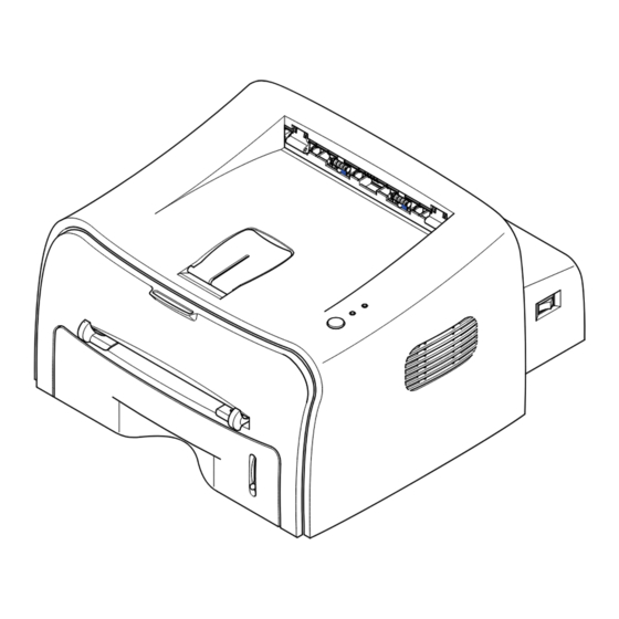
This chapter describes the functions and operating principal of the main component. 4.1 Printer Components 4.1.1 Front View Top output tray (Face down) Control Panel Output Support Front Cover Power switch Manual Feeder guide Manual Feeder Paper level indicator Tray Training Manual Samsung Electronics... - Page 13 S U M M A RY OF PRO D U C T 4.1.2 Rear View Rear output tray (Face up) Power receptacle Parallel port USB port 4.1.3 Inside View Toner cartridge Front Cover Training Manual Samsung Electronics...
- Page 14 If you press this button once again, this LED is off and the Toner Save mode is disabled. If the On Line/Error and Toner Save LEDs blink, your system has some problems. To solve the problem. Training Manual Samsung Electronics...
- Page 15 In Manual Feed mode, you can’t cancel the print job by pressing this button. Toner Save mode on/off In Ready mode, press this button to turn the Toner Save mode on or off. Training Manual Samsung Electronics...
- Page 16 S U M M A RY OF PRO D U C T 4.2 System Layout L S U Fuser Toner Cartridge MP Sensor Cassette Fuser Manual Feeder LSU(Laser Scan Unit) Transfer Roller Toner Cartridge PTL(Per-Tramsfer-Lamp) Training Manual Samsung Electronics...
- Page 17 - There are two methods, the existing method which use the Heat Lamp and the Q-PID which is developed by Samsung. 110V : Heat Lamp type Fuser 120V : Q-PID type Fuser 4.2.4.1 Temperature-Intercepting Device (Thermostat)
- Page 18 /HS YNC signal to arrange the vertical line of the image on the paper. After detecting the /HS YNC signal, the image data is sent to the LSU to arrange the its left margin on the paper. The one side of the polygon mirror is one line for scanning. Training Manual Samsung Electronics...
- Page 19 - Management of disusable toner: Collect the toner by using electric static (Clenerless Type- No disusable toner) - OPC Drum protecting Shutter: None - Classifying device for toner cartridge: ID is classified by interruption of the frame channel. Training Manual Samsung Electronics...
- Page 20 Electrophotography for printing. It is consisted of the circuits of the motor (paper feed, pass) driving, clutch driving, pre-transfer lamp driving, current driving, and fan driving. The signals from the paper feed jam sensor and paper empty sensor are directly inputted to the main board. Training Manual Samsung Electronics...
- Page 21 By operation of Actuator on the frame, the MP Sensor (Photo Interrupter) on the engine board informs the state of paper to CPU whether it is empty or not. It reads the D0 Bit of CPU for recognizing paper in MP, and paper is fed from MP if there is. Training Manual 4-10 Samsung Electronics...
- Page 22 IC) is used in this case. But, the resistance Rs value of sensing and the voltage value of the V refer- ence can be changed by motor driving voltage value. The motor driving voltage is calculated with the fol- lowing formula. Training Manual 4-11 Samsung Electronics...
- Page 23 S U M M A RY OF PRO D U C T 4.4 Main PBA (PCL Model) Training Manual 4-12 Samsung Electronics...
- Page 24 DRAM and uses it as PCL font. - Capacity : 8M Byte (Basic), upto 64M Byte (Factory Option) - Type : SDRAM 100MHz/133MHz , 16bit 4.4.3 Other The option PBA can be mounted for supporting the serial communication. Training Manual 4-13 Samsung Electronics...
- Page 25 LSU I/F PULSE WIDTH MODULATOR MOT OR CONTROLLER 128x16 x2 ADC (3CH) gCODEC PARALLEL PORT INTERFACE GRAPHIC EXECUTION UNIT MISC CONTROLLER ROTATOR/ ENGINE Comm. I/F SCALER/ HALFTONER 1024x8, 256x8x 4 INTERRUPT CTRL (5CH) TIME CONTROL UNIT Training Manual 4-14 Samsung Electronics...
- Page 26 - Output voltage rising time : 50ms Max - Output voltage falling time : 50ms Max - Output loading range : 10M•ÿ ~ 1000M - Output controlling signal (BIAS-PWM) : the CPU output is high when PWM is low. Training Manual 4-15 Samsung Electronics...
- Page 27 Consumption Power 3)Consumption Power Item System (+3.3V) (24V) Stand-By 1.0 A 0.4 A AVG : 55 Wh PRINTING 1.0 A 2.0 A AVG : 250 Wh Sleep-Mode 0.8A 0.4A AVG : 10 Wh Training Manual 4-16 Samsung Electronics...
- Page 28 1) Triac (THY1) feature - 12A,600V SWITCHING 2) Phototriac Coupler (PC3) - Turn On If Current : 15mA ~ 50mA(Design: 16mA) - High Repetive Peak Off State Voltage : Min 600V Training Manual 4-17 Samsung Electronics...
- Page 29 AD converter. The voltage value for impressing to the transfer roller is decided by the changed value. Training Manual 4-18 Samsung Electronics...
- Page 30 The temperature after the 3 seconds is checked. If it is over 240°C, it is error. • If the temperature has been higher than 220°C over 25 seconds, it is an error even through the temperature doesn’t reach 240°C. Training Manual 4-19 Samsung Electronics...
- Page 31 4.6.4.3 What is the Q-PID Method? The Q-PID is developed by Samsung, and it saves the preheating time in half in comparison with the exist- ed method. It saves not only the printing time for initial print but also it saves the printing speed for the reattempting print after for a while.
-
Page 32: Disassembly And Reassembly
3. Unplug the power cord. 4. Use a flat and clean surface. 5. Replace only with authorized components. 6. Do not force plastic-material components. 7. Make sure all components are in their proper position. Training Manual Samsung Electronics... - Page 33 2. Remove the Front Cover in the direction of 5. Remove the Top Cover in the direction of arrow. arrow. Top Cover Front Cover 3. Remove four screws. 6. Remove the Rear Cover from the Top Cover. Rear Cover Training Manual Samsung Electronics...
- Page 34 3. Remove two screws and take the Thermostat out of the Fuser. Thermostat 7. Remove the Thermister from the Fuser Cover. 4. Remove two screws and take the Halogen Lamp out of the Heat Roller. Heat Roller Thermister Halogen Lamp Training Manual Samsung Electronics...
- Page 35 2. Unplug two connectors(Block) from the boards, then remove four screws. Fuser Ass’y 5. Remove one screw and take the Idle Gear out. Idle Gear 3. Remove two screws and take the Thermostat out of the Fuser. Thermostat Training Manual Samsung Electronics...
- Page 36 Fuser Cover Unit-Brush Heat Roller 8. Remove one screw and separate Thermister from the inter connector Fuser Cover. Caution: Be careful not to damage or contaminate the surface of the roller when assembling/disassembling the heat roller. Thermister Training Manual Samsung Electronics...
- Page 37 - Top Cover(see page 5-2) 2. Remove two screws and unplug one connector from the Frame. 5. Unplug four screws and take the LSU out. 3. Remove the LED PBA Ass’y as shown below. LED PBA Cover Training Manual Samsung Electronics...
- Page 38 5.7 Driver Ass’y 1. Before you remove the Fuser, you should 3. Unplug one connector from the Driver Ass’y remove: - Top Cover(see page 5-2) Drive Ass'y 2. Remove the six screws from the Drive Ass’y. Training Manual Samsung Electronics...
- Page 39 1. Before you remove the Fuser, you should remove: - Top Cover(see page 5-2) Main PBA - Engine Shield Ass’y(see page 5-8) 2. Unplug one connector and remove five screws from the Main PBA. Then lift the Main PBA out, as shown below. Training Manual Samsung Electronics...
- Page 40 - Top Cover(see page 5-2) - Engine Shield Ass’y(see page 5-8) 2. Unplug one connector and remove three screws then take the Inlet Ass’y out. Inlet Bracket 4. Remove three screws and take The SMPS out. SMPS Training Manual Samsung Electronics...
- Page 41 - LSU(see page 5-6) Lens Holder 2. Remove three screws and take the Transfer Earth out. Transfer Earth 4. Unlatch the Bush and remove it. Then lift the Transfer Roller out, as shown below. Transfer Roller Bush Training Manual 5-10 Samsung Electronics...
- Page 42 6. Remove the Feed Roller and Feed Roller 1, as shown below. 3. Remove three screws from the Feed Bracket and take it out. Feed Roller Feed Bracket Feed Roller1 4. Remove the Idle Gear and Feed Gear2. Feed Gear2 Idle Gear Training Manual 5-11 Samsung Electronics...
- Page 43 - Drive Ass’y(see page 5-7) - Engine Shield Ass’y(see page 5-8) - Pick Up Roller(see page 5-11) 2. Remove two screw then remove The Manual (Pick up) Solenoid Solenoid and Pick Up Solenoid. (Manual) Solenoid Training Manual 5-12 Samsung Electronics...
-
Page 44: Alignment And Adjustments
COVER OPEN ERROR NO PAPERR PAPER JAM 0 PAPER JAM 1 PAPER JAM 2 LSU NOT READY DIAGNOSTIC DOWN SHIFT STOP MODE ENTER TO ENTER DIAGNOSTIC MODE, PUSH THREE BUTTONS SIMUL ANEOUSL AND TURN THE PRINTER POWER ON. Training Manual Samsung Electronics... - Page 45 The front part of paper is jammed just after passing through the discharge sensor. Out Bin Full The Out bin is filled with paper. LSU Not Ready LSU Scanner Motor not ready or Hsync signal not output. Training Manual Samsung Electronics...
- Page 46 [Up] button to Check LD. LD is functioning and the middle button is on. If the LD is normal, all LEDs are on. Pickup clutch on The Solenoid in the printer is in operation. To stop the operation, Press the button [shift] and [Enter] together. Training Manual Samsung Electronics...
- Page 47 Indicates the function of the Fan, same method of the code ‘07’. Manual Pickup Test : Indicates the function of th Manual Pickup, same method of the code ‘07’. Manual Sensor Test : Indicates the function of the Manual Sensor, same method of the code ‘07’. Training Manual Samsung Electronics...
- Page 48 READY Mode, and '88' shows in the DCU. In this mode, without any detection, the printer begins printing(trial printing and data from the PC). It is convenient to use this mode when the engine malfunction is detected in the control board. Training Manual Samsung Electronics...
- Page 49 4) The paper passed the paper exit sensor moves out from the set. (Jam 2 occurs sometime after if the tail- ing edge of the paper is not coming out from the set after the leading edge of paper passes the paper exit sensor.) Training Manual Samsung Electronics...
- Page 50 Continue with the next step. 4) Close the rear output tray. Open and close the front cover. Printing can be 2) Open the rear output tray. resumed. Training Manual Samsung Electronics...
- Page 51 1) Open the front cover and remove the 2) Gently pull the paper toward you. toner cartridge 3) Check that there is no other paper in the printer. 4) Reinstall the toner cartridge, and then close the cover. Printing can be resumed. Training Manual Samsung Electronics...
- Page 52 • Do not use creased, damp or highly curled paper. • Do not mix paper types in the input tray. • Use only recommended print media. • Ensure that the recommended print side is facing down when loading paper into the input tray. Training Manual Samsung Electronics...
- Page 53 Hold down the Cancel button for about 6 seconds to print a configuration sheet. 2) The Demo page or the configuration sheet shows the printer’s current configuration. <Demo Page : ML-1710> <Demo Page : ML-1750> Training Manual 6-10 Samsung Electronics...
- Page 54 3) Your printer automatically picks up a sheet of paper from the tray and prints out a cleaning sheet with dust or toner particles on it. Note: The cartridge cleaning process takes some time. To stop printing, turn the power off. Training Manual 6-11 Samsung Electronics...
- Page 55 Environmental conditions and actual use will vary these factors. The cycle period given below is for reference only. COMPONENT REPLACEMENT CYCLE Pick-up Roller 60,000 Pages Paepr Feeding Roller(Friction Pad) 60,000 Pages Transfer Roller 60,000 Pages Fuser 60,000 Pages Toner Cartridge 3,000 Pages Training Manual 6-12 Samsung Electronics...
- Page 56 L S U Fuser Toner Cartridge MP Sensor L S U Tramsfer Roller OPC Drum Fuser Toner Cartridge Heat Roller Charge Roller MP Sensor Pressure Roller Supply Roller Developing Roller <Rollers Layout> Training Manual 6-13 Samsung Electronics...
- Page 57 ALIGNMENT & A D J U S T M E N T S Training Manual 6-14 Samsung Electronics...
-
Page 58: Troubleshooting
4. No. 4. : Open the front cover and check odically at the top of a black image. ribs that corresponds to the position of the voids. Remove if found. 5. If the problems are not solved, replace the developer cartridge. Training Manual Samsung Electronics... - Page 59 1, take measures as to replace the develop- er cartridge and try to print out. 5. Clean the inside of the set against the paper particles and foreign matter in order not to cause the trouble. Training Manual Samsung Electronics...
- Page 60 HVPS. in the side of the Developer and charge terminal of HVPS. 3. Replace the HVPS if not solved by the above direction 1 and 2. Training Manual Samsung Electronics...
- Page 61 4. Is the movement(Up and Down) of 4. Clean the bushing part of the transfer the transfer roller smooth? roller. 5. Is the HVPS normal? 5. If the problem is still not solved, replace the developer. Training Manual Samsung Electronics...
- Page 62 Digital Printer mal paper or transparencies such as OHP, the software application and after using return- Digital Printer higher transfer voltage is required. ing to the original mode is recommended. Digital Printer Digital Printer Digital Printer Training Manual Samsung Electronics...
- Page 63 2. If the transfer roller is contaminated, satins 2. If the transfer roller is contaminated, run PC on the face of page will occur. Cleaning Mode Print 2 or 3 times. Digital Printer And perform Self-Test 2 or 3 times to remove contamination. Training Manual Samsung Electronics...
- Page 64 2. Perform the engine self test using DCU to check if the Solenoid is normal.(refer to code 06) 3. If not solved by the above directions 1-2, Replace the engine board. 4. Turn the power off, delete the data of PC and try printing again. Training Manual Samsung Electronics...
- Page 65 3. Clean with soft cloth dampened with IPA(Isopropyl ter. Alcohol) or water. 4. If the paper feeds into the printer rand Jam 0 occurs, 4. Replace the SMPS-HVPS and/or Sensor. perform DCU to check feed-sensor of the engine board. Training Manual Samsung Electronics...
- Page 66 3. Remove the jammed paper after disassembling the fuser : Clean the surface of the pressure roller with dry gauze. • Remove the toner particles stained on the rib. • Check the assemblage and performance of the exit. Training Manual Samsung Electronics...
- Page 67 3. The surface of the heat roller with IPA or water 4. Check the warp or separation of the sprint claw and the holder plate claw, and then man- age it. Training Manual 7-10 Samsung Electronics...
- Page 68 2. How to remove the rolled in the OPC Drum. • Remove the paper while turning the OPC Drum against the ongoing direction. • C;eam fomger[romts on the OPC Drum spft;u with IPA(Isopropyl Alcohol) or tissue. Training Manual 7-11 Samsung Electronics...
- Page 69 Solution DCU Mode : Perform DCU diagnostic code 05. If the DCU Replace LSU. error code 95 is displayed, replace LSU. If you cannot solve the problem after you replace LSU, replace the main board. Training Manual 7-12 Samsung Electronics...
- Page 70 1. Bending or deformation of the actuator of the paper sen- 1. Replace the defective actuator. sor. 2. The function of the engine board is defective Perform. 2. Replace the engine board. DCU mode : Perform DCU diagnostic code 8. Training Manual 7-13 Samsung Electronics...
- Page 71 Main Control board. Perform DCU Connect. mode : If Error state '64' occurs, Check the related codes of the Cover Open Error 2. Replace the Main Control board or Cover Open S/W. Training Manual 7-14 Samsung Electronics...
- Page 72 1. Replace the power supply cord or SMPS. 2. Check the inferiority of LED-Panel on the front-cover if 2. Replace the control board. the LED of Panel does not appear after normal warming- 3. Replace the LED-panel. Training Manual 7-15 Samsung Electronics...
- Page 73 1. If the supply of +24v is unstable in the Main Control board 1. Replace LSU. linking with LSU, check drive by DCU Mode : LSU Check -05- LSU Motor on. 2. Replace the Main Control board. Training Manual 7-16 Samsung Electronics...
- Page 74 7.4 Toner Cartridge Service It is not guaranteed for the default caused by using other toner cartridge other than the cartridge supplied by the Samsung Electronic or caused by non-licensed refill production. 7.4.1 Precautions on Safe-keeping of Toner Cartridge Excessive exposure to direct light more than a few minutes may cause damage to the cartridge.
- Page 75 (1)Check whether foreign sub- stances or toner are stuck to the terminal (contact point) of the developer. (2)Check whether the state of the terminal assembly is normal. 3. If it cannot be recycled: Replace the developer. Training Manual 7-18 Samsung Electronics...
- Page 76 2 times. (2)Check whether the state of (2)If toner nearly being expired the terminal assembly is nor- are collected to use, it is mal. judged as the recycled devel- oper. Training Manual 7-19 Samsung Electronics...
- Page 77 4. If the scanner needs to be connected to the printer, 4. Check if the printer cable is directly connected to periph- first the remove the scanner from the PC to see if the eral devices printer is properly working alone. Training Manual 7-20 Samsung Electronics...
- Page 78 Turn the PC and printer off, and reboot the system to print again. If not solved, double-click the printer in my computer If the regular fonts are not printed this time again. the cable must be defective so replace the cable with new one. Training Manual 7-21 Samsung Electronics...
- Page 79 3. Delete the unnecessary files to secure enough (The printing job sometimes stops or due to insufficient space of the hard disk and start printing job again. virtual memory, but it actually comes from the insuffi- cient space of the hard disk.) Training Manual 7-22 Samsung Electronics...
- Page 80 Before choosing the document, the menu is still inactive. Or put the document out of the list and repeat the routine as in the above or finish the spool manager. Training Manual 7-23 Samsung Electronics...
-
Page 81: Exploded Views And Parts List
5-4. Fuser Unit Assembly ......page(5-8) 5-5. Cassette Unit Assembly ......page(5-10) Training Manual Samsung Electronics... -
Page 82: Main Assembly
EXPLODED VIEW & PARTS LIST 8.1 Main Assembly Training Manual Samsung Electronics... - Page 83 14-1 CBF HARNESS-MAIN_SMPS JC39-00240A 14-2 SMPS-HVPS HPHR(110V) JC44-00045A 110V 14-3 BRACKET-INLET JC61-00601A 14-4 SHIELD-ENGINE JC63-00107A 14-5 SCREW-TIPTITE 6003-000264 14-6 SCREW-TIPTITE 6003-000119 14-7 SCREW-TIPTITE 6003-000301 FAN-DC JC31-00027A 16-1 ROLLER-TRANSFER ROLLER JC66-00528A 16-2 GEAR-TRANSFER JC66-00395A CBF HARNESS-MOTOR JC39-00241A Training Manual Samsung Electronics...
-
Page 84: Frame Unit Assembly
EXPLODED VIEW & PARTS LIST 8.2 Frame Unit Assembly Training Manual Samsung Electronics... - Page 85 JC61-00588A SPRING-TR_L JC61-00047A SPRING-ACT_FEED 6107-001164 PMO-BUSHING TR_L JC72-00102A IPR-GROUND FUSER JC70-00310A SHAFT-FEED IDLE JC66-00527A BUSH-FEED IDLE JC61-00585A SPRING-FEED IDLE JC61-70958A IPR-P_GROUND_DRIVE2 JC70-00335A SPRING-CAM PICK-UP 6107-001170 CAM-PICK_UP JC66-00377A IPR-GROUND DRIVE JC70-00308A SOLENOID-HB (PICK-UP) JC33-00009A SOLENOID-HB (MANUAL) JC33-00010A Training Manual Samsung Electronics...
- Page 86 JC61-00586A 58-2 SHAFT-PICK_UP JC66-00399A 58-3 STOPPER-PICK_UP JC61-00593A 58-4 PMO-IDLE PICK_UP JC72-00982A 58-5 SPONGE-ROILLER PICK UP JC72-01231A 58-6 BUSH-PICK_UP_R JC61-00587A 58-7 HOUSING-PICK_UP JC61-00591A 59-1 GEAR-FEED 1 JC66-00393A 59-2 PMO-COLLAR_SPRING JC72-00978A 59-3 SPRING-CLUTCH 6107-001164 59-4 PMO-HUB CLUTCH JC72-00981A Training Manual Samsung Electronics...
-
Page 87: Drive Unit Assembly
O : Service available X : Service not available Description SEC.Code Q’ty Remark ELA HOU-RX DRIVE 1400 JC96-02733A BRACKET-GEAR 1400 JC61-00598A GEAR-FUSER DRV JC66-00388A GEAR-RDCN Z132/19 JC66-00391A GEAR-PICK_UP DRV JC66-00389A RING-E 6044-000231 BRACKET-MOTOR 1400 JC61-00599A GEAR-RDCN Z7128 JC66-00390A GEAR-RDCN Z7322 JC66-00392A MOTOR STEP-7.5 JC31-00028A Training Manual Samsung Electronics... -
Page 88: Fuser Unit Assembly
EXPLODED VIEW & PARTS LIST 8.4 Fuser Unit Assembly Training Manual Samsung Electronics... - Page 89 4713-001155 110V ROLLER-EXIT F_UP JC66-00380A MEC-ROLLER_PR(1400) JC66-00600A BEARING-PRESSURE JC66-10901A SPRING-PR(1400) 6107-001168 PMO-BUSHING TX JC72-00382A HOLDER-ACTUATOR JC61-00581A PMO-ACTUATOR_EXIT JC72-00987A IPR-FRAME_FUSER JC70-00317A GUIDE-INPUT JC61-00595A RMO-RUBBER_EXIT JC73-00017A “LABEL(P)-CAUTION, HOT_FUSER” JC68-30928D SPRING ETC-ACT_EXIT 6107-001165 NUT-HEXAGON 6021-000222 NEW-CLAW ASSY PLATE-CLAW JC61-00605A Training Manual Samsung Electronics...
-
Page 90: Cassette Unit Assembly
EXPLODED VIEW & PARTS LIST 8.5 Cassette Unit Assembly Training Manual 8-10 Samsung Electronics... - Page 91 JC61-00603A SPRING-KNOCK_UP 6107-001166 HOLDER-PAD JC61-00580A SPRING-FRICTION PAD JC61-70911A ROLLER-IDLE FEED JC66-00529A SPRING-FEED 6107-001047 PMO-PLATE_LOCKER JC72-00972A SPRING-LOCKER JG61-70531A ADJUST-CASSETTE_L JC70-00300A ADJUST-CASSETTE_R JC70-00301A GEAR-PINION JG66-40003A INDICATOR-LEVER INDICATOR JC64-00040A RPR-FRICTION PAD JC73-00140A IPR-PLATE PAD JC70-00314A RPR-PAD CASSETTE JC73-00141A Training Manual 8-11 Samsung Electronics...
-
Page 92: Block Diagram
BLOCK DIAGRAM 9. Block Diagram 9.1 PCL Model Training Manual Samsung Electronics... - Page 93 BLOCK DIAGRAM 9.2 SPL Model Training Manual Samsung Electronics...
-
Page 94: Connection Diagram
*FUSER ON +24VS *E xit Sensor +24VS LE D_ERROR LE D_DATA PANEL *THV PWM *K EY_DEMO HVPS *THV Eanble THV Read +3.3V *M HV P WM DCU_DATA *B IA S PWM DCU_CLK *M anual Sensor Training Manual 10-1 Samsung Electronics... - Page 95 D CU _D ATA PANEL D CU _C LK *K EY_D EMO G ND *TH V Ea nb le THV Re ad HV PS *MHV P WM *BIA S PWM *Manu a l Se nso r Training Manual 10-2 Samsung Electronics...
-
Page 96: Schematic Diagram
SCHEMATIC DIAGRAMS 11. Schematic Diagrams 11.1 PCL Main Circuit Diagram (1/7) Repair Manual 11-1 Samsung Electronics... - Page 97 SCHEMATIC DIAGRAMS PCL Main Circuit Diagram (2/7) Repair Manual 11-2 Samsung Electronics...
- Page 98 SCHEMATIC DIAGRAMS PCL Main Circuit Diagram (3/7) Repair Manual 11-3 Samsung Electronics...
- Page 99 SCHEMATIC DIAGRAMS PCL Main Circuit Diagram (4/7) Repair Manual 11-4 Samsung Electronics...
- Page 100 SCHEMATIC DIAGRAMS PCL Main Circuit Diagram (5/7) Repair Manual 11-5 Samsung Electronics...
- Page 101 SCHEMATIC DIAGRAMS PCL Main Circuit Diagram (6/7) Repair Manual 11-6 Samsung Electronics...
- Page 102 SCHEMATIC DIAGRAMS PCL Main Circuit Diagram (7/7) Repair Manual 11-7 Samsung Electronics...
- Page 103 SCHEMATIC DIAGRAMS 11.2 SPL Main Circuit Diagram (1/5) Repair Manual 11-8 Samsung Electronics...
- Page 104 SCHEMATIC DIAGRAMS SPL Main Circuit Diagram (2/5) Repair Manual 11-9 Samsung Electronics...
- Page 105 SCHEMATIC DIAGRAMS SPL Main Circuit Diagram (3/5) Repair Manual 11-10 Samsung Electronics...
- Page 106 SCHEMATIC DIAGRAMS SPL Main Circuit Diagram (4/5) Repair Manual 11-11 Samsung Electronics...
- Page 107 SCHEMATIC DIAGRAMS SPL Main Circuit Diagram (5/5) Repair Manual 11-12 Samsung Electronics...
- Page 108 THV-sen Q301 C945C-Y ¡ THV-EA D303 R306 C303 IT-01 1N4148 150KF Q302 C2383 C306 ZD301 D301 2.7V R304 C305 D1NL20U D304 R307 1/4W 4.7 INDEX 1N4148 150K D305 R308 1N4148 CON2-18 THV-READ U102-A C307 KA324 Repair Manual 11-13 Samsung Electronics...
- Page 109 R505 1N4148 ¡ BIAS-sen IT-01 C507 R514 Q503 C2316 R512 1/2W 50K 30KF Q502 D503 R515 C945C-Y C508 R509 D1NL20U MGR1/2W 15MF ZD502 1/4W 10 2.7V U103 24VS KA7805 C113 C112 25V 47uF 50V 10uF Repair Manual 11-14 Samsung Electronics...
- Page 110 C109 TLP3061S 1000uF 470uF 33uF R112 6.8K U101 5.6K-F TL431 R114 1W0.6 CON2-4,5,6 1/2W DGND 1.5K CON2-15(MANUAL) 332MAD CON2-16(THV-PWM) CON2-17(THV-EA) CON2-18(THV-READ) CON2-14,16(+24VS) CON2-19(MHV-PWM) CON2-20(BIAS-PWM) CON2-25(*FUSER-ON) CON2-21(LED-ERROR) CON2-22(LED-DATA) CON2-23(KEY-DEMO) CON2-24(FAN) CON2-25(FUSER-ON) CON2-26(EXIT) NO MARKING RESISTOR 1/8W-J(5%) Repair Manual 11-15 Samsung Electronics...
- Page 111 11.5 OTHER PBA Circuit DiagramS 3.3V 24VS CON3 R115 R116 R117 R118 D105 1N4003 35301-0350 R119 2.2K CON2-15(MANUAL) CON2-24(FAN) Q101 CON2-26(EXIT) KSC1008-Y R120 5.6K OP101 OP102 ITR-8406S ITR-8406S 3.3V 35303-0550 C111 CON2-21(LED-ERROR) CON2-22(LED-DATA) CON2-23(KEY-DEMO) CON4 Repair Manual 11-16 Samsung Electronics...
- Page 112 HUMMINGBIRD ERROR TEST 1. S ER VIC E ER R OR Item Phenomenon Measurement On Line/Error and Toner Save alternately light Check the fuser assembly, Controller and SMPS OPEN FUSER ERROR green for 1 second. and AC wire (DCU:60) Fuser On Line/Error and Toner Save alternately light OVER HEAT ERROR Check the fuser assembly, Controller and SMPS...
- Page 113 2. P A PER JAM Item Phenomenon Measurement JAM0 On Line/Error Lights red Check the Feed Clutch Operation and Controller (DCU:71) JAM1 PAPER JAM On Line/Error Lights red Check the Feed Sensor and Controller (DCU:72) JAM2 On Line/Error Lights red Check the Exit Sensor, Fuser Ass'y and Controller (DCU:73) 3.
- Page 114 DCU Function Table for ML-1710 Series N o. Fun ct ion En ter U p/ Dow n S to p R em ark Mot or Motor Run Motor Stop MH V Mhv On Mhv Off -1550V TH V( -) Thv Negative On Thv Negative Off TH V( +) Thv On...
- Page 115 2003. 01...
- Page 116 ELECTRONICS This service manual is also provided on the web, © Samsung Electronics Co.,Ltd. January 2003 the ITSELF system f Samsung Electronics Co., Ltd. Printed in Korea. http://itself.sec.samsung.co.kr VERSION NO. : 1.00 CODE : JC-0084A...