Advertisement
PUBLIC ADDRESS
AMPLIFIER
PBM-15
PBM-30
RISK OF ELECTRIC
SHOCK, DO NOT OPEN!
CAUTION: TO REDUCE THE RISK
OF ELECTRIC SHOCK, DO NOT
OPEN COVER. NO USER
SERVICEABLE PARTS INSIDE.
REFER SERVICING TO QUALIFIED
SERVICE PERSONNEL.
PRECAUTIONS
1.Unpacking
After removing the amplifier from the carton, inspect for any exterior damage to
the unit. If damage is noted, notify the carrier at once so that a claim can be
justified. Save all packing material. This is important when the claim is
processed.
2.Ventilation
To offset heat generated by the unit, it is necessary to provide ample ventilation
around the unit. Avoid blocking or impeding the ventilation holes on the unit. To
prevent unnecessary problems, install the unit on a place free from any
vibrations, direct sunlight, humidity or dust circulation.
3.Avoid spilling liquids or allowing materials to enter the cabinet
If the unit gets wet or any foreign material enters the cabinet, immediately
disconnect the A.C. line cord and consult your dealer or qualified technician.
INSTRUCTION
MANUAL
15 WATT RMS
30 WATT RMS
WARNING: TO PREVENT FIRE
OR SHOCK HAZARD, DO NOT
EXPOSE UNITS NOT
SPECIFICALLY DESIGNED FOR
OUTDOOR USE TO RAIN OR
MOISTURE.
WARNING: REMOVAL OF THE
COVER SHOULD ONLY BE PER-
FORMED BY QUALIFIED SERVICE
PERSONNEL - NOT USER SER-
VICEABLE. THE UNIT SHOULD
ALWAYS BE UNPLUGGED BEFORE
REMOVING THE COVER, AND
REMAIN UNPLUGGED WHILE THE
COVER IS REMOVED.
200 NEW HIGHWAY, AMITYVILLE, NY11701
PHONE : 1-800-645-5516, 631-957-8700 IN METRO NY
http://www.specotech.com
Advertisement
Table of Contents

Related Manuals for Speco PBM-15


Summary of Contents for Speco PBM-15
- Page 1 PUBLIC ADDRESS AMPLIFIER PBM-15 PBM-30 RISK OF ELECTRIC SHOCK, DO NOT OPEN! CAUTION: TO REDUCE THE RISK OF ELECTRIC SHOCK, DO NOT OPEN COVER. NO USER SERVICEABLE PARTS INSIDE. REFER SERVICING TO QUALIFIED SERVICE PERSONNEL. PRECAUTIONS 1.Unpacking After removing the amplifier from the carton, inspect for any exterior damage to the unit.
-
Page 2: Important Safety Instructions
IMPORTANT SAFETY INSTRUCTIONS 1. Read these instructions. 2. Keep these instructions. 3. Heed all warnings. 4. Follow all instructions. 5. Do not use this apparatus near water. 6. Clean only with dry cloth. 7. Do not block any ventilation openings. Install in accordance with the manufacturer’ s instructions. -
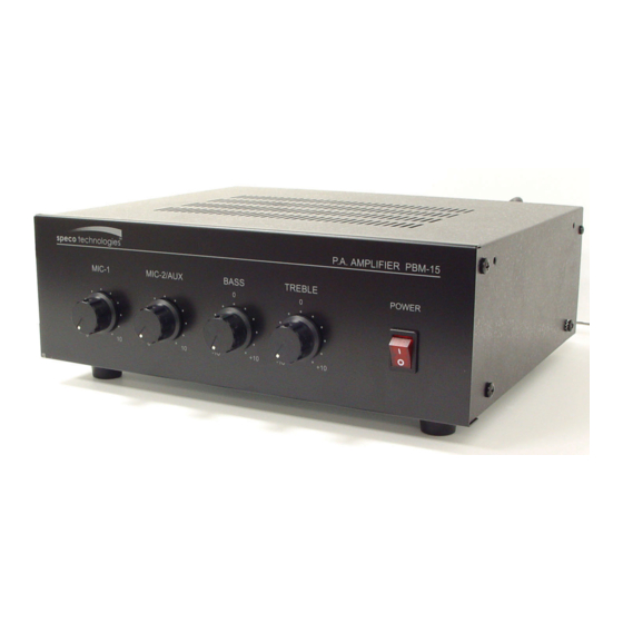
Page 3: Front Panel
Controls and Connections FRONT PANEL REAR PANEL FRONT PANEL 1) MIC-1 Volume control 2) MIC-2/AUX Volume control 3) BASS Control REAR PANEL 1) AC accessory outlet (Unswitched) 2) AC fuse holder 3) MOH output level control* 4) MIC-2/AUX input selector switch 5) AUX input RCA jacks 6) TEL/PAGING output level control** 7) TEL/PAGING input terminals(Balanced)**... - Page 4 FRONT PANEL 1) MIC-1 Volume control. Adjusts audio level of MIC-1. 2) MIC-2/AUX Volume control. Adjusts audio level of MIC-2/AUX. 3) Bass Control. Low frequency tone control. 4) Treble Control. High frequency tone control. 5) Power on/off switch with indicator. Illuminates when power is on. REAR PANEL 1) AC accessory outlet (Unswitched).
-
Page 5: Speaker Connection
Warning To overcome this potential problem, the electrical and the mechanical ground on the amplifier may be separated by completely removing the wire connecting the power source to ground. CONSULT AN ELECTRONICS TECHNICIAN TO ACCOMPLISH THIS TO AVOID POTENTIAL PERSONAL INJURY OR A HAZARDOUS CONDITION. SPEAKER CONNECTION The rear panel of the amplifier contains a 7 screw terminal strip for connection of speakers. -
Page 6: Speaker Impedances
25V and 70V CONSTANT LINE VOLTAGE CONNECTIONS (refer to figure 4). IMPORTANT NOTICE: When the 25V and 70V constant line voltages are used, a line matching transformer must be used with each speaker. All transformers must be connected in parallel. HOW TO CONNECT LINE MATCHING TRANSFORMERS IN PARALLEL (25 VOLT LINE OR 70 VOLT LINE) ALWAYS CONNECT LINE TRANSFORMERS IN PARALLEL... -
Page 7: Cable Requirements
CABLE REQUIREMENTS Output cabling need not be shielded in most cases and should be of sufficient gauge to minimize losses due to the resistance of the wire over long runs (insertion loss). Cable thinner than 18 gauge is not recommended. Long runs require 16 gauge or heavier. In some cases, where the output cable is run in close proximity to unshielded intercom cables, electrical cables, radio transmission antenna or other sources of interference or when the amplifier is being used for paging from a telephone system, the amplifier may require shielded... - Page 8 If Sum Wattage Total is between 217 and 240 Watts If Sum Wattage Total is between 241 and 288 Watts * RMS Amplifier used in conjuction with Speco Technologies’ P-240A Power Booster Amp Speco Technologies 200 New Highway, Amityville, NY 11701 Web: www.specotech.com...
-
Page 9: Specifications
(Use # PBM-RK1 rack mount bracket) *MOH = Music on hold SPECIFICATIONS Public Address Mixer Power Amplifier PBM-15 **Factory set : - 40 dB PBM-30 AC 120V, 50/60Hz 30W RMS 50~15 KHz ±3dB 1% or less at 1KHz at rated output TEL :100mV/600 Ohm, Balanced MIC-1:1.0mV/600 Ohm, Balanced...
Need help?
Do you have a question about the PBM-15 and is the answer not in the manual?
Questions and answers