Table of Contents
Advertisement
Quick Links
Advertisement
Table of Contents

Summary of Contents for Get Control E84
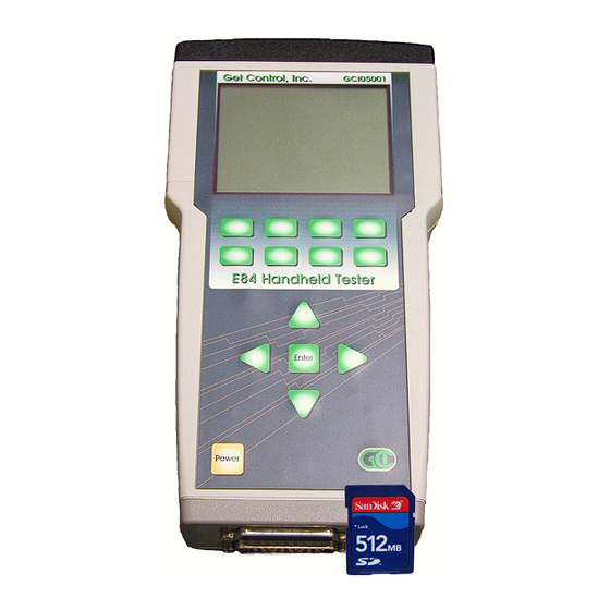
- Page 1 Get Control, Inc. E84 Handheld Tester GCI05001 Users Manual Rev 3.1 March 1, 2006...
-
Page 3: Table Of Contents
Setting E84 Timeout Values ........ - Page 4 Charging the Rechargeable Battery Pack ..........48 HHT Firmware Field Update .
- Page 5 Figure 42 - Tester Configuration - E84 Timeouts ....... . .
- Page 6 Figure 58 - Example Help System File ..........67 Figure 59 - Tester Configuration Menu .
-
Page 7: Introduction
The GCI Handheld Tester is an efficient tool for quickly testing, trouble-shooting, and resolving E84 problems. It is a self-contained, battery operated tool integrating the industry-leading automated load and unload routines provided in the GCI E84 Emulator. It incorporates a number of industry firsts to quickly locate answers to E84 problems: •... -
Page 8: Navigating The E84 Hht Menus
Test results data can be saved in the HHT’s Paperless Storage System (PSS). The PSS provides a convenient method of documenting E84 troubleshooting activities. Data stored in the PSS can be transferred to a computer for detailed analysis, reporting or archival purposes. -
Page 9: Sd Card Format
Card will erase the card, resulting in the loss of any data stored on it. File Organization HHT Test results files are organized by Tool ID. Each E84 interface in the FAB is associated with an EFEM (Equipment Front End Module) on a specific Tool. When testing a specific EFEM, it is convenient to organize all stored test results together. -
Page 10: Tool Id File Format
.DAT extension indicates it is a binary file that is formatted for Figure 4 - Stored Test Results Files use with the GCI E84 Analysis Application. A second file of the same name, with a .TXT extension, contains additional test details in a formatted ASCII report. This file can be viewed with any text editor. -
Page 11: Editing Tool Details
Using The Handheld Tester Pressing the Save soft key brings up the Save Test Results screen. A list of Tool ID’s is displayed on the left side of the screen. Information on the currently selected Tool ID is displayed on the right side of the screen. Use the Up and Down Arrow keys, along with the Top, Bottom, Prev, and Next soft keys to move the Tool selection cursor to the desired Tool (in ?, TOOL001A is selected). -
Page 12: Figure 8 - Edit Tool Details Screen (2)
Using The Handheld Tester The soft keys are operated similar to the keys on a cellular phone. Press the soft key once for the first displayed character, twice for the second, etc. A rectangle is drawn around the current field being modified. A vertical bar is displayed at the location of the character cursor. -
Page 13: Main Test Menu
(AMHS) of the E84 handoff. This mode is used when testing a load port. During Passive Mode tests, the HHT simulates the passive side (EFEM) of the E84 handoff. This mode is used when testing a delivery vehicle. Use the numbered soft keys to select the desired test mode. -
Page 14: Figure 11 - Active Mode Load Cycle - Internal Ir
Press the CS_0 and CS_1 soft keys to toggle the CS_0 and CS_1 output states prior to handoff. CS_0 is set exclusively for a single load port per E84 port configuration (HHT default). CS_0 and CS_1 select left and right load port respectively in a one E84 port per two load ports configuration. -
Page 15: Electrical Tests
Figure 16 - Power Supply Voltage Test should leave pin 22 unconnected. The active equipment supplies voltage on pin 22. The E84 Specification further states that the voltage level must remain with +18 VDC and +30 VDC under both no-load and full-load conditions. -
Page 16: Displaying Signal Voltage And Current Levels
Use the Electrical Test screens to verify that an E84 interface is electrically compliant. Input and output signals must match the voltage and current levels defined in the E84 Specification. For signals in the OFF state, voltage levels must remain above 1.8 VDC, with current levels less than 200... -
Page 17: Electrical Test Manual Mode
PAGE 21 Using The Handheld Tester IR Transceiver Test The E84 HHT IR Transceiver Test, Test Menu Option 3, performs a complete end-to-end functional test on E84 compatible optical transceivers. Plug the IR Transceiver (UUT) into the passive DB-25 on the rear panel of the HHT. -
Page 18: Ir Transceiver Auto Test Screen
Using The Handheld Tester IR Transceiver Auto Test Screen The IR Transceiver Auto Test changes the state of each Output and Input on the transceiver and performs verification. Voltage levels are recorded for each signal, in both the ON and OFF states. The screen displays the current state of each output and input. -
Page 19: Ir Error Detail Screen
Using The Handheld Tester IR Error Detail Screen The IR Test Error Details screen displays specific details about each error that the IR Transceiver test detected. It reports opens circuits, shorts circuits, and unexpected patterns. Figure 25 and Figure 26 show example IR Test Error Detail Screens. -
Page 20: Ir On / Off State Levels
Using The Handheld Tester IR On / OFF State Levels This screen shows voltage and current measurements taken during the IR Transceiver Test. Press the Voltage soft key to display voltage measurements. Press the Current soft key to display current measurements. Press the ON State soft key to display the voltage or current of the inputs and outputs as measured in their ON state. -
Page 21: Manual Control Screen
Press the Pause soft key once to pause the Manual Control real-time graph window. The Pause soft key is a toggle switch, remaining ON until pressed a second time. The HHT does not update the real-time graph when the Pause soft key is selected. The HHT continues to scan E84 inputs, and maintain E84 PAGE 29 Using The Handheld Tester outputs during the Pause. -
Page 22: Interface To Dld
HHT and the DLD. Typically, the DLD would be installed between the Process Equipment and it’s PI/O Transceiver. Alternately, the DLD can be plugged directly into the HHT’s Passive E84 Port. The HHT connects to the DLD using a straight through 9-pin male-to-female cable. -
Page 23: Dld Log File
Select a Tool ID to save the DLD Log file to (see Saving Test Results Files above for details on selecting the Tool ID). DLD Logs transferred to a computer can be analyzed using the GCI E84 Analysis Application (Version 2.70 or newer). -
Page 24: Howto: Download The Dld Log - Step By Step Instructions
If the HHT is unable to connect to the DLD, make sure that the DLD is firmly plugged into its power source. If it still can not connect, and the HHT is not the DLD's power supplier, try disconnecting the DLD from the E84 interface to which it is connected, and connect it to the HHT instead. -
Page 25: Dld Configuration Screen
Trapping and Idle Noise. Error Trapping limits the DLD to Figure 37 - DLD Configuration Screen record only failed E84 transactions. Idle Noise limits the special Error Trapping mode to record only those errors that occur during an E84 transaction. -
Page 26: Stored Test Data
Using The Handheld Tester remain selected until the update is completed. The DLD settings display is refreshed following the DLD update. Press the Exit soft key to close the DLD Configuration Screen and return to the Interface to DLD Screen. PAGE 39 Using The Handheld Tester Stored Test Data... -
Page 27: Stored Test Data File List
Using The Handheld Tester Stored Test Data File List The File List screen is displayed when the View soft key is pressed on the Stored Test Data Menu. The left side of the screen shows details on the selected Tool ID. The right side of the screen shows a File List of stored test results files for the selected Tool. -
Page 28: Configuring The Tester
PAGE 43 Using The Handheld Tester Setting E84 Timeout Values Press the Timeouts soft key to modify the E84 timeouts. The E84 Timeouts section title is underlined to show that it is selected. A rectangle is drawn around TA1. Use the Up and Down arrow keys to increment and decrement TA1 respectively. -
Page 29: Setting Power Timeouts
ON. Settings The Power timeout determines the number of minutes of non-use that must pass before the E84 HHT powers itself off. The Power timeout is disabled during DLD Live Mode, and all Cycle, IR, Electrical and Manual Test Screens to allow for extended analysis. -
Page 30: Setting Screen Contrast
Charging time is 4 hours. When fully charged, the batteries provide 8 to 16 hours of use depending on the E84 HHT functions performed. The useable battery range is 8 to 12 Volts. Battery voltage is displayed on the configuration menu for reference. -
Page 31: Hht Firmware Field Update
The Charging Batteries screen displays the current battery voltage, battery temperature, charge current, charge time, and maximum time to charge completion. After the batteries are fully charged, the E84 HHT terminates the charge cycle, and displays final charge statistics. -
Page 32: Field Update Errors
Using The Handheld Tester Field Update Errors If any errors occur during the Field Update process, an error message is displayed. Figure 49 shows an example error message. This message is displayed if the Field Update Screen is entered with no SD Card inserted. If an error occurs, the Field Update is terminated. -
Page 33: Field Update Verification
Using The Handheld Tester Field Update Verification The Confirm HHT Update screen is displayed to verify that the user desires to update the HHT’s firmware. A warning message is displayed indicating that the update process cannot be interrupted or undone. To cancel the update, and return to the HHT’s Main Menu, press and release the Logo key. -
Page 34: Figure 53 - Writing Update To Internal Flash
Using The Handheld Tester When all update data has been loaded, the progress bar is cleared, and a new message is displayed, indicating that the HHT is writing the update data to internal flash memory. As the update is written into internal flash memory, the progress bar will fill. -
Page 35: Emulator Test Suite Addendum
Get Control, Inc. E84 Handheld Tester GCI05001 Emulator Test Suite Addendum March 1, 2006... -
Page 37: Overview
This document details the porting of the GCI E84 Emulator Test Suite into the GCI HHT. Due to memory constraints, a subset of the E84 Emulator Test Suite is implemented. The HHT Test Suite is functionally equivalent to the E84 Emulator Test Suite, with the following limitations: •... -
Page 38: Running The Hht Test Suite
Handheld Tester Emulator Test Suite Running the HHT Test Suite Selecting the Emulator Test Suite option from the Standard Cycle Test Menu (Figure 54) will display the first test in the HHT Test Suite (Voltage Test). Each test in the HHT Test Suite has an opening screen describing operator setup instructions. -
Page 39: Hht Test Suite Help System
Handheld Tester Emulator Test Suite If all tests in the selected results file had passed, the HHT will advance to the first test in the Test Suite. Each test setup screen will show the status of the current test from the results file: ‘Untested’... -
Page 40: Active Mode Test Plan
Why we run this test: The E84 Specification defines TP1 as the maximum time between L_REQ / U_REQ ON and TR_REQ ON (Table 8). Section 6.3 specifies that equipment should inform the operator about handoff timeout errors. Additionally, in section A1-4.71 requires that the equipment display details about the timeout error including: Timer name, Timer Description and... -
Page 41: Active Mode Functionality Tests
Verify Configurable Passive Equipment Timers Using the equipment user interface, verify that the passive equipment timers (TP1 through TP5) are configurable within the range specified in E84 (1 to 999) and make note of the default settings: Test A is not directly supported on the HHT. The Operator should verify that the UUT’s timers are configurable using the... -
Page 42: Active Mode Functionality Test C
Handheld Tester Emulator Test Suite The HHT continuously monitors and displays voltage levels while the Power Supply Voltage Test screen is displayed. The HHT continuously: • takes a No Load voltage measurement • switches in the Load resistor • allows the voltage to stabilize •... -
Page 43: Nd Run
Handheld Tester Emulator Test Suite The operator is prompted to load a FOUP onto the UUT at the proper point in the E84 handoff. A TP3 timeout counter is displayed in the status window showing the operator how much time is available to load the FOUP. -
Page 44: Active Mode Functionality Test D
Unload Cycle screens. The Unload Cycle test prompts the operator to remove a FOUP from the UUT at the proper point in the E84 handoff. A Test completion message (pass or fail) is displayed, and recorded in the HHT Test Suite Test Results data structure. -
Page 45: Nd Run
The test completes when the UUT drops HO_AVBL (indicating a load conflict), or a TA1 or TA2 timeout occurs. All three cases are Pass conditions. If the UUT advances the E84 handoff by setting the L_REQ and READY signals, the test is halted with a failure. -
Page 46: Active Mode Functionality Test F
Handheld Tester Emulator Test Suite Active Mode Functionality Test F Verify Handoff Available Signal Note: This test uses a standard load cycle to verify the Handoff Available sequence. The Load Port under test must be empty prior to initiating the test. Verify handoff available sequence. The setup screen for Test F instructs the operator to modify (on the UUT’s GUI) the passive equipments TP1 timeout to at least 15 seconds. -
Page 47: Active Mode Functionality Test G
Test G is implemented using a standard Load Cycle test. The Load Cycle screen is displayed, and the HHT advances the E84 handshake up to the point where the UUT sets it’s L_REQ signal. At this point, the HHT locks it’s outputs, and displays a status message indicating that the TP1 timeout should occur when the displayed count down timer expires. -
Page 48: Active Mode Functionality Test I
Test I is implemented using a standard Load Cycle test. The Load Cycle screen is displayed, and the HHT advances the E84 handshake up to the point where the UUT is waiting for the delivery of a FOUP. At this point, a normal Load Cycle would place the FOUP onto the UUT. -
Page 49: Active Mode Functionality Test L
Test K is implemented using a standard Load Cycle test. The Load Cycle screen is displayed, and the HHT advances the E84 handshake up to the point where the UUT drops it’s READY signal following the successful delivery of a FOUP. -
Page 50: Active Mode Functionality Test M
Test M is implemented using a standard Load Cycle test. The Load Cycle screen is displayed, and the HHT advances the E84 handshake up to the point where the UUT is waiting for the delivery of a FOUP. At this point, the HHT prompts the operator to activate the Figure 87 - Test M Setup Screen Placement sensor(s) only. -
Page 51: Active Mode Functionality Test N
Active Mode Functionality Test O Verify Port Sensors - Part 3 Verify Port Sensors tied to E84 signals - Part 3 (Placement sensor(s) deactivated during Unload, but Presence sensor(s) is not). The setup screen for Test O instructs the operator to activate all Placement and Presence sensors on the UUT. -
Page 52: Active Mode Functionality Test P
Active Mode Functionality Test P Verify Port Sensors - Part 4 Verify Port Sensors tied to E84 signals - Part 4 (Presence sensor(s) deactivated during Unload, but Placement sensor(s) is not). The setup screen for Test P instructs the operator to activate all Placement and Presence sensors on the UUT. -
Page 53: Active Mode Functionality Test Q
UUT prior to starting the test. The Unload Cycle screen is displayed, and the HHT advances the E84 handshake up to the point where the UUT is waiting for the removal of the FOUP. Figure 95 - Test Q Setup Screen At this point, the HHT prompts the operator to press the UUT’s... -
Page 54: Hht Test Suite Results
Handheld Tester Emulator Test Suite When the HHT detects a drop in the ES signal, it drops all of it’s signals (BUSY, TR_REQ, VALID, CS_0). The HHT then prompts the operator to clear the E-Stop condition (release the EMO button). The UUT should turn it’s ES signal back ON. If the HHT detects the ES signal turning ON, it will mark the test as passed. -
Page 55: Emulator Test Suite Worksheet
Get Control, Inc. E84 Handheld Tester GCI05001 Emulator Test Suite Worksheet March 1, 2006... -
Page 57: Hht Test Suite Worksheet
Setup Procedure The unit under test (UUT) must be fully assembled as for normal operation with power applied. The E84 HHT must be set to run the Emulator Test Suite (select option 1 - Standard Cycle Test from Main Test Menu, then option 5 - Emulator Test Suite). - Page 58 Handheld Tester Emulator Test Suite Worksheet [P] [F] A. Using the equipment user interface, verify that the passive equipment timers (TP1 through TP5) are configurable within the range specified in E84 (1 to 999) and make note of the default settings.
-
Page 59: Figure 99 - Single Handoff - Load
5. Set the TR_REQ signal ON on the E84 HHT 6. Verify that the equipment turns the READY signal ON 7. Set the BUSY signal ON on the E84 HHT and place the FOUP on the loadport associated with the E84 interface being tested 8. - Page 60 6. Set the TR_REQ signal ON on the E84 HHT 7. Verify that the equipment turns the READY signal ON 8. Set the BUSY signal ON on the E84 HHT and remove the FOUP from the loadport associated with the E84 interface being tested 9.
- Page 61 [P] [F] E. Handoff available signal test for load: All steps must occur in the prescribed order to pass: 1. Verify that the HO_AVBL signal is ON on the equipment 2. Activate the presence sensor(s) on the loadport associated with the E84 interface being tested 3.
- Page 62 5. Set the TR_REQ signal ON on the E84 HHT 6. Verify that the equipment turns the READY signal ON 7. Set the BUSY signal ON on the E84 HHT but DO NOT place the FOUP on the loadport for a time exceeding TP3 8.
- Page 63 5. Set the TR_REQ signal ON on the E84 HHT 6. Verify that the equipment turns the READY signal ON 7. Set the BUSY signal ON on the E84 HHT and place the FOUP on the loadport associated with the E84 interface being tested 8.
- Page 64 5. Set the TR_REQ signal ON on the E84 HHT 6. Verify that the equipment turns the READY signal ON 7. Set the BUSY signal ON on the E84 HHT and activate all of the placement sensor(s) only on the loadport associated with the E84 interface being tested 8.
- Page 65 5. Set the TR_REQ signal ON on the E84 HHT 6. Verify that the equipment turns the READY signal ON 7. Set the BUSY signal ON on the E84 HHT and activate the presence sensor(s) only on the loadport associated with the E84 interface being tested 8.
- Page 66 6. Set the TR_REQ signal ON on the E84 HHT 7. Verify that the equipment turns the READY signal ON 8. Set the BUSY signal ON on the E84 HHT and deactivate the presence sensor(s) only from the loadport associated with the E84 interface being tested 9.
Need help?
Do you have a question about the E84 and is the answer not in the manual?
Questions and answers