Table of Contents
Advertisement
Advertisement
Table of Contents

Related Manuals for Extreme Networks Extreme 7520 Series


Summary of Contents for Extreme Networks Extreme 7520 Series
- Page 1 Extreme 7520 Hardware Installation Guide 9037389-00 Rev. AA July 2023...
- Page 2 Extreme Networks, Inc. reserves the right to make changes in specifications and other information contained in this document and its website without prior notice. The reader should in all cases consult representatives of Extreme Networks to determine whether any such changes have been made.
-
Page 3: Table Of Contents
Preface.............................. 7 Audience........................................7 Text Conventions....................................7 Documentation and Training..............................9 Help and Support....................................9 Subscribe to Product Announcements.........................10 Send Feedback....................................10 Extreme 7520 Series Overview....................12 Management......................................12 Cooling........................................12 Power Supplies....................................13 Stacking........................................13 Operating Temperatures................................14 Feature Licensing....................................14 Extreme 7520-48Y-8C Switch Features........................... 14 Extreme 7520-48XT-6C Switch Features.........................15... - Page 4 Table of Contents Meet Building and Electrical Codes........................38 Set Up the Wiring Closet..............................39 Control the Temperature..............................40 Control the Humidity Level..............................41 Protect Your System from ESD (Electrostatic Discharge)............... 41 Rack Specifications and Recommendations......................41 Mechanical Recommendations for the Rack....................42 Ground the Rack..................................42 Provide Adequate Space for the Rack........................
- Page 5 Table of Contents Remove the Switch from a Two-Post Rack......................76 Monitor the Switch........................78 System Status LEDs..................................78 RJ-45 Management Port LEDs..............................79 SFP+/SFP28 Port LEDs for the 7520-48Y-8C......................80 1G/10G RJ45 Port LEDs for the 7520-48XT-6C......................81 QSFP28 Port LEDs....................................81 800 W AC Power Supply LEDs...............................82 800 W DC Power Supply LEDs..............................82 Technical Specifications......................
- Page 6 Table of Contents Japan power cord ...................................112 Index............................... 113 Extreme 7520 Hardware Installation Guide...
-
Page 7: Preface
Extreme Networks devices. Note If the information in an installation note or release note shipped with your Extreme Networks equipment differs from the information in this guide, follow the installation or release note. Text Conventions Unless otherwise noted, information in this document applies to all supported environments for the products in question. - Page 8 Text Conventions Preface Table 1: Notes and warnings Icon Notice type Alerts you to... Helpful tips and notices for using the product Note Useful information or instructions Important Important features or instructions Caution Risk of personal injury, system damage, or loss of data Warning Risk of severe personal injury...
-
Page 9: Documentation And Training
Extreme Optics Compatibility Other resources such as white papers, data sheets, and case studies Extreme Networks offers product training courses, both online and in person, as well as specialized certifications. For details, visit www.extremenetworks.com/education/. Help and Support If you require assistance, contact Extreme Networks using one of the following... -
Page 10: Subscribe To Product Announcements
1 (408) 579 2826. For the support phone number in your country, visit: www.extremenetworks.com/support/contact Before contacting Extreme Networks for technical support, have the following information ready: • Your Extreme Networks service contract number, or serial numbers for all involved Extreme Networks products • A description of the failure •... - Page 11 Preface Send Feedback Provide the publication title, part number, and as much detail as possible, including the topic heading and page number if applicable, as well as your suggestions for improvement. Extreme 7520 Hardware Installation Guide...
-
Page 12: Extreme 7520 Series Overview
14 Extreme 7520-48XT-6C Switch Features on page 15 The Extreme 7520 Series are purpose-built 48-port 10Gb and 48-port 25Gb switches designed for high-performance aggregation and core applications. The Extreme 7520 provides end-to-end secure network segmentation and advanced policy capabilities. -
Page 13: Power Supplies
Extreme 7520 Series Overview Power Supplies Fans are ordered separately for base models 7520-48Y-8C and 7520-48XT-6C. Fans are included with other models. Power Supplies Hot swappable 800 W AC or DC power supplies are available to power the switch. The power supplies have integrated cooling fans that operate independently of the switch fans. -
Page 14: Operating Temperatures
Operating Temperatures Extreme 7520 Series Overview Operating Temperatures The 7520 Series supports the following operating temperatures with front-to-back cooling: • 0°C (32°F) to 50°C (122°F) at sea level • 0°C (32°F) to 40°C (104°F) up to 3000 m (10,000 ft) -
Page 15: Extreme 7520-48Xt-6C Switch Features
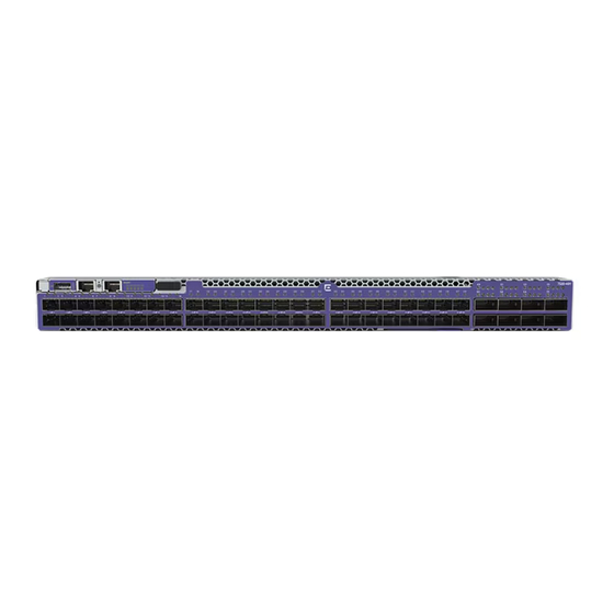
Extreme 7520 Series Overview Extreme 7520-48XT-6C Switch Features • 1 10/100/1000BASE-T out-of-band management port • 1 Type A USB storage port Figure 1: 7520-48Y-8C Switch Front Panel 1 = 1/10/25Gbps SFP28 3 = 10/100/1000BASE-T OOB 5 = RJ-45 serial ports... - Page 16 Extreme 7520-48XT-6C Switch Features Extreme 7520 Series Overview The front panel of the switch includes: • 48 1/10Gbps 10GBaseT RJ-45 ports • 6 40/100Gbps QSFP28 ports • 1 RJ-45 serial console port • 1 10/100/1000BASE-T out-of-band management port • 1 Type A USB storage port...
-
Page 17: Port Partitions
Port Partitions On some ExtremeSwitching switch models, you can configure QSFP28 and QSFP+ ports either as single ports or as multiple, partitioned ports. In a partitioned port, with appropriate cabling, the original physical port can accommodate multiple data lanes at lower bandwidths. -
Page 18: Power Supplies For Use With Your Switch
Power Supplies for Use with Your Switch Each 7520 Series switch runs with two replaceable internal power supply modules that provide all of the power needed for the switch to operate. You can remove one power supply module without interrupting the switch's operation. Supported power supply configurations include two 800 W AC power supply modules, two 800 W DC power supply modules, or one 800 W AC and one 800 W DC power supply module. -
Page 19: 800 W Ac Power Supply
800W AC power supply - back-to-front airflow (part no. XN-ACPWR-800W-R) Note AC power input cords are not provided with AC power supplies. You can order an appropriate cord from Extreme Networks or from your local supplier. The power cord must meet the requirements listed in Power Cord Requirements for AC-Powered Switches and AC Power Supplies on page 98. -
Page 20: Build Stacks
Build Stacks Introduction to Stacking on page 20 Plan to Create Your Stack on page 29 Set up the Physical Stack on page 33 A stack consists of a group of up to eight switches that are connected to form a ring. The stack offers the combined port capacity of the individual switches;... -
Page 21: Build Basic Stacks
More information to answer your questions about stacking and help you plan your configuration is available on the Extreme Networks GTAC Knowledge Base. Build Basic Stacks A stack can be created in either of two ways: •... -
Page 22: Summitstack Topologies
SummitStack Topologies Build Stacks Slot Numbers in Stacks A switch stack can be thought of as a virtual chassis. Each switch (node) operates as if it were occupying a slot in a chassis and is controlled by the primary. The high-speed stacking links function like the backplane links of a chassis. - Page 23 Build Stacks SummitStack Topologies Figure 6: Example of a Stack, Showing the Active Topology and the Stack Topology A stack is the collection of all switches, or nodes, that are cabled together to form one virtual switch using the Switch Engine SummitStack feature. The maximum cable length supported between switches depends on the types of switches in your stack, the installed option cards, and the configured stacking ports.
- Page 24 SummitStack Topologies Build Stacks Figure 7: Graphical Representation of a Ring Topology Figure 8 shows what the same ring topology would look in actual practice. Each switch in the rack is connected to the switch above it and the switch below it. To complete the ring, a longer cable connects Switch 1 with Switch 8.
-
Page 25: Summitstack Terms
Build Stacks SummitStack Terms Figure 9: Daisy Chain Topology You might need to use a daisy chain topology while adding a new node, removing a node, or joining two stacks. If you are using a daisy chain topology, the possibility of a dual primary condition increases. - Page 26 SummitStack Terms Build Stacks Table 5: List of Stacking Terms (continued) Term Description Alternate stacking A stacking configuration in which stack members are connected using 10-Gbps Ethernet data ports that have been configured for stacking. These ports are located either on the switch itself or on option cards installed on the rear of the switch.
- Page 27 Build Stacks SummitStack Terms Table 5: List of Stacking Terms (continued) Term Description Candidate node A node that is a potential member of an active topology, or an active node that is already a member of an active topology. A candidate node may or may not be an active mode –...
- Page 28 SummitStack Terms Build Stacks Table 5: List of Stacking Terms (continued) Term Description Failover The process of changing the backup node to the primary node when the original primary node has failed. When a primary node fails, if a backup node is present, and if that node has completed its initial synchronization with the primary node, then the backup node assumes the role of primary node.
-
Page 29: Plan To Create Your Stack
Build Stacks Plan to Create Your Stack Plan to Create Your Stack Use the information in the following topics to plan the physical makeup of your stack – switches, versatile interface modules (VIMs), and cables – and the stacking protocols you will use. -
Page 30: Recommendations For Configuring Stacks
Recommendations for Configuring Stacks Build Stacks • To provide management access to the stack in case of a failure in the primary switch, connect all switches that will participate in redundancy to your management network using the Ethernet management port on each switch. •... -
Page 31: Combine Switches From Different Series
Select Stacking Cables Stacking connections using the native stacking ports require stacking cables that are specific to the type of stacking port. These cables are available from Extreme Networks in lengths from 0.5 meter to 100 meters. Note... - Page 32 Use the Extreme Stacking Tool Build Stacks To use the Stacking Tool, follow these steps. 1. Open the Stacking Tool (https://stackingtool.extremenetworks.com/StackingTool/) in a web browser. Note The Stacking Tool is also available in the Support Tools section of the Extreme Portal. 2.
-
Page 33: Set Up The Physical Stack
Build Stacks Set up the Physical Stack In addition to statistics and recommendations, colors in the display show whether the selected switch models and stacking methods are compatible. Table 6: Colors in the Stacking Tool Display Color Meaning Green Compatible and preferred Blue Compatible Yellow... - Page 34 Connect the Switches to Form the Stack Ring Build Stacks Example: Basic Stack with Four Switches This example shows a stack of four switches in a single rack. The slot numbers presume a console connection to the switch at the top of the physical stack.
- Page 35 Build Stacks Connect the Switches to Form the Stack Ring Figure 12: SummitStack Cable Connections Using Eight Switches with Integrated SummitStack Ports Table 8 lists the recommended order for connecting the stacking ports in this example. Table 8: Basic Stack with Eight Switches: Connections Connect this slot and port .
-
Page 36: Connect Your Stack To The Management Network
Connect Your Stack to the Management Network Build Stacks Rack A Rack B Rack C Rack D Rack E Slot 1 Slot 2 Slot 5 Slot 3 Slot 4 Figure 13: Top-of-Rack Stack Installation Table 9 lists the recommended order for connecting the stacking ports in this example. Table 9: Stacked Switches across Several Racks: Connections Connect this slot and port . -
Page 37: Site Preparation
Site Preparation Plan Your Site on page 37 Operating Environment Requirements on page 38 Rack Specifications and Recommendations on page 41 Evaluate and Meet Cable Requirements on page 43 Meet Power Requirements on page 49 Follow Applicable Industry Standards on page 51 By carefully planning your site, you can maximize the performance of your existing network and ensure that it is ready to migrate to future networking technologies. -
Page 38: Operating Environment Requirements
After examining your physical site and verifying that all environment requirements are met, evaluate and compare your existing cable plant with the requirements of the Extreme Networks equipment to determine if you need to install new cables. 3. Meeting power requirements. -
Page 39: Set Up The Wiring Closet
Site Preparation Set Up the Wiring Closet The organizations listed in Table 10 are authorities on electrical codes. Table 10: Authorities on Electrical Codes Organization Address Web Site URL National Electrical Code (NEC) Classification NFPA www.nfpa.org/ (USA only) 1 Batterymarch Recognized authority on safe electrical wiring. -
Page 40: Control The Temperature
Consult an electrical contractor for commercial building and wiring specifications. Control the Temperature Extreme Networks equipment generates a significant amount of heat. It is essential that you provide a temperature-controlled environment for both performance and safety. Install the equipment only in a temperature- and humidity-controlled indoor area that is free of airborne materials that can conduct electricity. -
Page 41: Control The Humidity Level
Site Preparation Control the Humidity Level Safeguards are built into all Extreme Networks switches and power supply units to minimize the risk of fire. Table 11: Thermal Shutdown and Restart Behavior Switch Model(s) Behavior All models When internal system temperatures exceed the thermal shutdown temperature limit (typically about 20°C higher than normal system... -
Page 42: Mechanical Recommendations For The Rack
Mechanical Recommendations for the Rack Site Preparation Mechanical Recommendations for the Rack Use equipment racks that meet the following mechanical recommendations: • Use an open style, 19-inch rack to facilitate easy maintenance and to provide proper ventilation. • Use a rack made of steel or aluminum. •... -
Page 43: Secure The Rack
(61 cm) of space behind the mounted equipment. Extra room on each side is optional. Warning Extreme Networks switches do not have a switch for turning power to the unit on and off. For systems using an AC power supply, power to the switch is disconnected by removing the wall plug from the electrical outlet. -
Page 44: Label Cables And Keep Accurate Records
• Assign a unique identification number to each equipment rack. • Identify all wiring closets by labeling the front panel of your Extreme Networks equipment and other hardware. • Keep accurate and current cable identification records. - Page 45 Site Preparation Install Cable • Use plenum-rated cable when it is necessary for safety and fire rating requirements. Consult your local building codes to determine when it is appropriate to use plenum-rated cable, or refer to IEC standard 850. • Keep all ports and connectors free of dust.
- Page 46 Install Cable Site Preparation installation. Ensure that the bend radius for fiber optic cables is equal to at least 5 cm (2 in) for each 90-degree turn as shown in Figure Note Kinks and sharp bends can destroy or impair the cable’s ability to convey light pulses accurately from one end of the cable to the other.
- Page 47 10GBASE-LRM SFP+ 62.5/125 µm multimode fiber – (1310nm optical window) 1 Proprietary to Extreme Networks. Connections between two Extreme Networks 1000BASE-LX interfaces that use 10/125 µm single-mode fiber can use a maximum distance of 10,000 meters. Extreme 7520 Hardware Installation Guide...
-
Page 48: Use Rj45 Connector Jackets
Use RJ45 Connector Jackets Site Preparation Table 12: Cable Distances and Types (continued) Standard Media Type MHz•km Maximum Rating Distance (Meters) 10GBASE-ER SFP+ 10/125 µm single-mode fiber – 40,000 (1550nm optical window) 1000BASE-T Category 5 and higher UTP – cable 100BASE-TX Category 5 and higher UTP –... -
Page 49: Meet Power Requirements
Site Preparation Meet Power Requirements RF interference can cause degradation of signal quality, and, in an Ethernet network environment, can cause excessive collisions, loss of link status, or other physical layer problems that can lead to poor performance or loss of communication. To prevent RF interference, avoid the following situations: •... -
Page 50: Power Cord Requirements
Most ExtremeSwitching switches do not ship with power cords. Visit www.extremenetworks.com/product/powercords/ for information on selecting and purchasing the correct power cords for use with specific Extreme Networks equipment. The web page provides specifications for power cords in each country so that you can purchase cords locally. -
Page 51: Follow Applicable Industry Standards
UPS transition time is sometimes called UPS transition times vary between UPS models and implementations, but shorter transition times are preferred. For Extreme Networks stacking products, a UPS transition time of 20 milliseconds or less ensures optimum performance and minimizes service interruptions. -
Page 52: Install The Switch
Turn on the Switch on page 66 Connect Network Interface Cables on page 67 Before you attempt to install or remove an Extreme Networks switch, read the precautions in Safety Considerations for Installation on page 52. Extreme Networks switches fit into standard 19-inch equipment racks. -
Page 53: What You Will Need For The Installation
37, and ensure that you have the appropriate people and tools on hand. Installing Extreme Networks switches is easiest when there are two people to maneuver the switch and attach mounting hardware. Provide enough space in front of and behind the switch so that you can service it easily. -
Page 54: Four-Post Rack Mount
Four-Post Rack Mount Install the Switch • Two-post rack, using mounting brackets (not provided) to attach the front or the middle of the switch to the posts. To attach a switch to a two-post rack, a four-post rack, or a cabinet, follow these steps. Note Take care to load the rack so that it is not top-heavy. - Page 55 Install the Switch Four-Post Rack Mount Figure 19: Attaching the Outer Rail 3. Attach an inner rail to the side of the unit, using the M4 screws. • If you are using the 1U long rack ears (already attached to the inner rail): Ensure that the rack ear is flush with the either the front or the rear panel of the unit and continue to step 4.
- Page 56 Four-Post Rack Mount Install the Switch Figure 21: Front Installation: Attaching a Rack Ear Figure 22: Rear Installation: Attaching a Rack Ear 4. Repeat steps 2 and 3 for the other side of the device. 5. Insert the device into the rail kit. To install the device in the front of the rack, slide the device into the outer rails in the front of the rack.
-
Page 57: Two-Post Rack Mount
Install the Switch Two-Post Rack Mount Figure 23: Front Installation: Inserting the Device To install the device in the rear of the rack, slide the device into the outer rails in the rear of the rack. Figure 24: Rear Installation: Inserting the Device Secure the device to the rack using the thumb screws on the mounting ears. - Page 58 Two-Post Rack Mount Install the Switch • Mid-mount The side of the switch has different sets of holes for attaching mounting brackets in either configuration. Brackets for a two-post mount are not included in the box with the switch. However, they can be ordered separately using part number XN-2P-RKMT299.
-
Page 59: Install Optional Components
For a list of the optical components supported with ExtremeSwitching devices, see the Extreme Optics website. Pluggable Transceiver Modules Extreme Networks offers several optical transceiver modules for transmitting and receiving data over optical fiber rather than through electrical wires. Extreme 7520 Hardware Installation Guide... -
Page 60: Optical Cables
Optical Cables Install the Switch Optical Cables Direct-attach copper and fiber cables provide connections between populated SFP+, SFP28, QSFP+, and QSFP28 ports. Breakout cables The copper breakout cables are terminated with optical connectors and are available in 1m, 3m, 5m, or greater lengths. No additional connectors or cabling are required when using the copper breakout. - Page 61 Install the Switch Install an 800 W Internal AC Power Supply All installed power supplies must have the same airflow direction (front-to-back or back-to-front) and must match the airflow direction of the installed fan modules. Warning To prevent an electrical hazard, make sure that the AC power cord is not connected to the power supply before you install the power supply in the power supply bay.
- Page 62 Install an 800 W Internal AC Power Supply Install the Switch Figure 28: Installing an 800 W AC Power Supply 5. Push the power supply in until the latch snaps into place. Do not slam the power supply into the switch. Note If power supplies are not installed in both power supply bays, be sure to install a cover over the unoccupied bay.
-
Page 63: Install An 800 W Internal Dc Power Supply
Install the Switch Install an 800 W Internal DC Power Supply Figure 29: Power Supply with Power Cord and Retainer Attached d. Snap the clip firmly around the connector. 7. Connect the other end of the power cord to an AC power outlet. Warning Always make sure that the source outlet is properly grounded before plugging the AC power cord into the AC power supply. - Page 64 Required Tools and Materials for Installing a 800 W DC Power Supply You need the following tools and materials to install or remove a 800 W DC power supply in an Extreme Networks switch. • #6 AWG copper cable for grounding the power supply and connecting the power supply to the DC power source.
- Page 65 Install the Switch Install an 800 W Internal DC Power Supply 2. Repeat step for the other cable wire. Installing an 800 W DC Power Supply Before installing an 800 W DC power supply (part no. XN-DCPWR-800W-F or XN- DCPWR-800W-R), verify that the airflow direction for the power supply is the same as the airflow direction of the installed fan modules in the switch.
-
Page 66: Turn On The Switch
An AC power cord is not included with the AC power supply. You can purchase AC power cords for use in the US and Canada from Extreme Networks or from your local supplier. The cord must meet the requirements listed in... -
Page 67: Connect Network Interface Cables
Install the Switch Connect Network Interface Cables Connect Network Interface Cables Use the appropriate type of cable to connect the ports of your switch to another switch or router. Cable Type Maximum Distance CAT5E 55 meters CAT6 55 meters CAT6A 100 meters Working carefully, one port at a time, do the following: 1. -
Page 68: Activate And Verify The Switch
Activate and Verify the Switch Connect to a Management Console on page 68 Log in for the First Time on Switch Engine on page 68 Configure the Switch's IP Address for the Management VLAN on page 70 Change the Switch OS via the Bootloader Menu on page 70 Change the Switch OS via the Startup Menu on page 71... - Page 69 Activate and Verify the Switch Log in for the First Time on Switch Engine To perform the initial login and complete initial configuration tasks, follow these steps. 1. Use a terminal emulator such as PuTTY or TeraTerm to connect to the switch through the serial port connection.
-
Page 70: Configure The Switch's Ip Address For The Management Vlan
Configure the Switch's IP Address for the Management VLAN Activate and Verify the Switch Configure the Switch's IP Address for the Management VLAN You can configure the switch's IP address for the management virtual LAN (VLAN). Note The management port is part of the mgmt VLAN. This VLAN membership cannot be changed. -
Page 71: Change The Switch Os Via The Startup Menu
Activate and Verify the Switch Change the Switch OS via the Startup Menu Change the Switch OS via the Startup Menu Onboard your switch with Switch Engine™. Log in or create your XIQ administrator account in order to select your switch operating system with XIQ at https:// extremecloudiq.com. - Page 72 Log In for the First Time on Fabric Engine Activate and Verify the Switch When prompted for the password, enter rwa. When you are logged in with the role-based authentical level of rwa, you can configure the login and password values for the other role-based authentication levels. Extreme 7520 Hardware Installation Guide...
-
Page 73: Remove And Replace Components
• If the power supply module has a blue tab, the airflow is back-to-front. To replace one or both AC internal power supplies in an Extreme 7520 Series switch, follow the steps in Install an 800 W Internal AC Power Supply on page 60. -
Page 74: Remove The Device From The Rack
Remove the Device from the Rack Remove and Replace Components • If the fan module has a blue tab, the airflow is back-to-front. Use a fan module labeled Air In. Note The operating-system software cannot display the airflow direction. Before you begin, have the replacement fan module on hand so that you can complete the replacement promptly. - Page 75 Remove and Replace Components Remove the Switch from a Four-Post Rack Figure 30: Disconnect latch for removal b. Disengage the retainers that are connecting the mounting brackets with the sliding rails on both sides. c. Carefully slide the device out of the slider assembly and place it on a flat surface. You can leave the slider assemblies in place.
-
Page 76: Remove The Switch From A Two-Post Rack
Remove the Switch from a Two-Post Rack Remove and Replace Components Figure 31: Removing the Slider Assembly: Rear Rack Post e. Release the tab that holds the front of the slider assembly to the front rack post, and pull the pegs out. Figure 32: Removing the Slider Assembly: Front Rack Post f. - Page 77 Remove and Replace Components Remove the Switch from a Two-Post Rack If the device cannot be tilted (because other equipment is mounted directly above and below), remove one or two mounting brackets from the device and then slide the device out. If you plan to use the device again later, store it with the mounting brackets attached.
-
Page 78: Monitor The Switch
Monitor the Switch System Status LEDs on page 78 RJ-45 Management Port LEDs on page 79 SFP+/SFP28 Port LEDs for the 7520-48Y-8C on page 80 1G/10G RJ45 Port LEDs for the 7520-48XT-6C on page 81 QSFP28 Port LEDs on page 81 800 W AC Power Supply LEDs on page 82 800 W DC Power Supply LEDs... -
Page 79: Management Port Leds
Monitor the Switch RJ-45 Management Port LEDs Table 13: System Status LEDs (continued) Color/State Description PSU Status No power. Green Power on. Main and Standby output enabled with no PSU warning or fault detected. Blinking amber Warning. Power supply warning detected. -
Page 80: Sfp+/Sfp28 Port Leds For The 7520-48Y-8C
SFP+/SFP28 Port LEDs for the 7520-48Y-8C Monitor the Switch Table 14: 10/100/1000Base-T RJ-45 Management Port LEDs (continued) Color/State Description Link/Activity Green The port has link established. There is no data activity. Blinking green The port has link established and there is data activity. -
Page 81: 10G Rj45 Port Leds For The 7520-48Xt-6C
Monitor the Switch 1G/10G RJ45 Port LEDs for the 7520-48XT-6C 1G/10G RJ45 Port LEDs for the 7520-48XT-6C Each port has one LED to indicate link or activity. The following table describes the states for the LED. Table 16: 1G/10G RJ45 Port LEDs for the 7520-48XT-6C State Description Link/Activity... -
Page 82: Ac Power Supply Leds
800 W AC Power Supply LEDs Monitor the Switch Table 17: (continued) Port Configuration LEDs State Description 25 Gb or 10 Gb All LEDs No link. Link is active, but there is no activity. Blinking Link is active and there is activity. All LEDs blinking Switch is beaconing. - Page 83 Monitor the Switch 800 W DC Power Supply LEDs Table 19: 800 W DC Power Supply LED Status Indications (continued) Label and Description State Meaning Color OUT OK DC output DC output OK (Green) Good (solid) Off or DC output fail Blinkin IN OK DC input...
-
Page 84: Technical Specifications
Power Cord Requirements for AC-Powered Switches and AC Power Supplies on page 98 Console Connector Pinouts on page 99 This section lists technical specifications for the hardware products described in this document. The Extreme 7520 Series includes the following switches: • 7520-48Y-8C (base) switch • 7520-48Y-8C-AC-F switch •... -
Page 85: Weights And Physical Dimensions
Technical Specifications Weights and Physical Dimensions Software Specifications Description Maximum number of MCT switches 2 Maximum number of Bridge 2,048 Domains Maximum IPv4 unicast routes 128,000 Maximum IPv6 unicast routes 10,000 Maximum IPv4 host routes 47,000 Maximum IPv6 host routes 33,000 Maximum jumbo frame size 9,126 bytes... - Page 86 Weights and Physical Dimensions Technical Specifications Table 20: 7520 Series Unpackaged Dimensions (continued) XN-FAN-001-F: Fan unit, front-to-back or XN- Height: 4.0 cm (1.57 in) FAN-001-R: Fan Unit back-to-front Width: 4.0 cm (1.57 in) Length: 13.4 cm (5.28 in) XN-4P-RKMT298 - Four-post rack mount kit Height: 2.1 cm (0.83 in) (included with switch) Width: 4.4 cm (1.73 in)
-
Page 87: Acoustic Specifications
Technical Specifications Acoustic Specifications Table 22: 7520 Series Packaged Dimensions (continued) XN-4P-RKMT298 - Four-post rack mount kit Height: 7.0 cm (2.76 in) (included with switch) Width: 11.0 cm (4.33 in) Length: 84.0 cm (33.07 in) XN-2P-RKMT299 - Two-post rack mount kit Height: 6.9 cm (2.72 in) (separately orderable) Width: 11.0 cm (4.33 in) -
Page 88: Fan Tray And Speed Variation
Fan Tray and Speed Variation Technical Specifications Fan Tray and Speed Variation Fan speeds are adjusted based on calculations of the temperatures on all sensors. Due to one fan being located behind the other, air pushed from one fan can cause the other fan in the module to run at a higher speed. -
Page 89: 7520-48Y
Technical Specifications 7520-48Y 7520-48Y The following tables provide AC and DC power consumption information for the 8520-48Y switch models. Table 25: AC IN: 220V Item Test Consumption (W) Notes Mode Dual Power Single Power PSU1 PSU2 Empty 1. No fiber transceivers inserted Model 2. - Page 90 7520-48Y Technical Specifications Table 26: AC IN: 110V (continued) Item Test Consumption (W) Notes Mode Dual Power Single Power PSU1 PSU2 Typical 1. Snake test with 70% traffic Model load (1518 byte packet length) 2. 85% fan duty Stress 1. Snake test with 100% traffic Model load (64 byte packet length) 2.
-
Page 91: 7520-48Xt
Technical Specifications 7520-48XT 7520-48XT The following tables provide AC and DC power consumption information for the 8520-48XT switch models. Table 28: AC IN: 220V Item Test Consumption (W) Notes Mode Dual Power Single Power PSU1 PSU2 Empty 148.5 275.5 1. No fiber transceivers inserted Model 2. - Page 92 7520-48XT Technical Specifications Table 29: AC IN: 110V (continued) Item Test Consumption (W) Notes Mode Dual Power Single Power PSU1 PSU2 Typical 1. Snake test with 70% traffic Model load (1518 byte packet length) 2. 85% fan duty Stress 1. Snake test with 100% traffic Model load (64 byte packet length) 2.
-
Page 93: Power And Heat Dissipation
Technical Specifications Power and Heat Dissipation Power and Heat Dissipation The following table includes power and heat dissipation information for the Extreme 7520 switches. Switch Minimum Heat Minimum Power Maximum Heat Maximum Power Model Dissipation Consumption Dissipation Consumption (BTU/hr) (Idle, (Watts) (Idle, no (BTU/hr) (Fans (Watts) (Fans... -
Page 94: Standards
Standards Technical Specifications Standards Table 31: Safety Standards North American Safety UL 60950-1 of ITE UL/CuL 62368-1 Listed CSA 22.2 No. 60950-1 2nd edition 2014 (Canada) Complies with FCC 21CFR 1040.10 (U.S. Laser Safety) CDRH Letter of Approval (US FDA Approval) European Safety of ITE EN 60950-1 EN 62368-1... - Page 95 Technical Specifications Standards Table 32: EMI/EMC Standards (continued) International EMC CISPR 32, Class A (International Emissions) certifications AS/NZS CISPR32 CISPR 24 Class A (International Immunity) IEC 61000-4-2/EN 61000-4-2 Electrostatic Discharge, 8kV Contact, 15 kV Air, Criteria B IEC 61000-4-3/EN 61000-4-3 Radiated Immunity 10V/m, Criteria A IEC 61000-4-4/EN 61000-4-4 Transient Burst, 2 kV, Criteria B...
-
Page 96: Environmental Standards
Environmental Standards Technical Specifications Environmental Standards Operating conditions • 7520-48Y and 7520-48XT, AC/DC, front-to- back: 0°C (32°F) to 50°C (122°F) at sea level; 0°C (32°F) to 40°C (104°F) up to 3000 m (10,000 ft) • 7520-48Y and 7520-48XT, AC/DC, back-to- front: 0°C (32°F) to 45°C (113°F) at sea level;... - Page 97 Technical Specifications 800 W Power Supplies Technical Specifications Table 35: 800 W Power Supplies: Unpackaged Dimensions 800 W power supply – AC (front-to-back or back- Height: 4.00 cm (1.57 in) to-front airflow) Width: 7.35 cm (2.89 in) 800 W power supply – DC (front-to-back or back- Depth: 18.84 cm (7.42 in) to-front airflow) Table 36: 800 W Power Supplies: Unpackaged Weight...
-
Page 98: Power Cord Requirements For Ac-Powered Switches And Ac Power Supplies
Power Cord Requirements for AC-Powered Switches and AC Power Supplies Technical Specifications Table 39: Power Specifications (AC Power Supplies) (continued) 18 AWG (0.75 mm 2 ) up to 6 feet or 2 meters Power supply cord gauge 16 AWG (1.0 mm 2 ) over 6 feet Efficiency 94% at 50% load and 91% at 100% load Table 40: Power Specifications (DC Power Supplies) -
Page 99: Console Connector Pinouts
Technical Specifications Console Connector Pinouts Console Connector Pinouts Table 42 describes the pinouts for a DB-9 console plug connector. Table 42: Pinouts for the DB-9 Console Connector Function Pin Number Direction DCD (data carrier detect) RXD (receive data) TXD (transmit data) DTR (data terminal ready) GND (ground) DSR (data set ready) - Page 100 Console Connector Pinouts Technical Specifications Figure 34: PC-AT Serial Null-modem Cable Pinouts Table 43 shows the pinouts for the RJ45 console port on the ExtremeSwitching switches. Table 43: RJ45 Console Port on Switch Function Pin Number Direction RTS (request to send) DTR (data carrier detect) TXD (transmit data) GND (ground)
- Page 101 Technical Specifications Console Connector Pinouts Table 44: Pinouts for an RJ45 to DB-9 Adapter (continued) Signal RJ45 Pin DB-9 Pin DSR (data set ready) RTS (request to send) Extreme 7520 Hardware Installation Guide...
-
Page 102: Safety Information
Only trained and qualified service personnel (as defined in IEC 60950-1 and AS/NZS 3260) should install, replace, or perform service to Extreme Networks switches and their components. Qualified personnel have read all related installation manuals, have the... -
Page 103: General Safety Precautions
Make sure that your power supplies meet the site DC power or AC power requirements of all the network equipment. • Racks for Extreme Networks equipment must be permanently attached to the floor. Failure to stabilize the rack can cause the rack to tip over when the equipment is removed for servicing. -
Page 104: Maintenance Safety
Fiber Optic Ports and Optical Safety The following safety warnings apply to all optical devices used in Extreme Networks equipment that are removable or directly installed in an I/O module or chassis system. Such devices include but are not limited to gigabit interface converters (GBICs), small form factor pluggable (SFP) modules (or mini-GBICs), QSFP+ modules, XENPAK transceivers, and XFP laser optic modules. -
Page 105: Cable Routing For Lan Systems
Cable Routing for LAN Systems Extreme Networks equipment meets the requirements for LAN system equipment. LAN systems are designed for intra-building installations; that is, cable runs between devices must be in the same building as the connected units, except under the conditions listed in the next paragraph. -
Page 106: Select Power Supply Cords
When you install DC power supplies or connect DC power: • Extreme Networks DC power supplies do not have switches for turning the unit on and off. Make sure that the DC circuit is de-energized before connecting or disconnecting the DC power cord at the DC input power socket. -
Page 107: Battery Notice
Safety Information Battery Notice purchase a cord from your local supplier. Requirements for the power cord are listed in the Technical Specifications for your product. To locate a Sales Manager or Partner in your region, visit www.extremenetworks.com/ partners/where-to-buy. Note This equipment is not intended to be directly powered by power distribution systems where phase-phase voltages exceed 240 VAC (2P+PE), such as those used in Norway, France, and other countries. -
Page 108: Regulatory Information
Regulatory Information CE statement on page 108 EMC Warnings on page 109 China and Taiwan: Restriction of Hazardous Substances (ROHS) on page 109 BSMI statement (Taiwan) on page 109 Canadian requirements on page 109 China CCC statement on page 110 Australia (RCM) on page 110 Federal Communications Commission (FCC) Notice... -
Page 109: Emc Warnings
Regulatory Information EMC Warnings EMC Warnings China CQC Warning China and Taiwan: Restriction of Hazardous Substances (ROHS) For more information, see https://www.extremenetworks.com/company/legal/ restriction-of-hazardous-substances/. BSMI statement (Taiwan) Canadian requirements This Class A digital apparatus meets all requirements of the Canadian Interference- Causing Equipment Regulations, ICES-003 Class A. -
Page 110: China Ccc Statement
China CCC statement Regulatory Information China CCC statement Australia (RCM) Warning This equipment is compliant with Class B of CISPR 32. In a residential environment, this equipment may cause radio interference. Federal Communications Commission (FCC) Notice This device complies with Part 15 of the FCC rules. Operation is subject to the following two conditions: (1) this device may not cause harmful interference, and (2) this Extreme 7520 Hardware Installation Guide... -
Page 111: Germany Statement
Regulatory Information Germany statement device must accept any interference received, including interference that may cause undesired operation. Note This equipment has been tested and found to comply with the limits for a class A digital device, pursuant to Part 15 of the FCC rules. These limits are designed to provide reasonable protection against harmful interference when the equipment is operated in a commercial environment. -
Page 112: Japan Power Cord
Japan power cord Regulatory Information Japan power cord English translation of above statement ATTENTION: Never use the power cord packed with your equipment for other products. Extreme 7520 Hardware Installation Guide... - Page 113 Index Numerics brackets, for mounting in rack 74, 76 building codes 38 1G/10G RJ45 port LEDs 81 Building Industry Consulting Service International. 800 W AC power supply see BICSI features 18, 19 LEDs 82 specifications 97 800 W DC power supply cabinet connecting ground wire 65 attaching switch 53, 54, 57...
- Page 114 Index (continued) console port equipment rack Extreme 7520 12 mechanical recommendations 42 for stacked configurations 36 mounting holes 42 on switch 99 securing 43 settings 68 service access 42 control path 26 space requirements 42 conventions notice icons 7 discharge from cable 44 text 7 system protection 41 cooling...
- Page 115 Index (continued) mounting brackets removing 74, 76 industry standards 51 multiple-rack stacking 35 initial device login 68 initial switch login 71 install AC power supplies 60 native stacking 25 internal power supplies 60 native stacking ports 21 power supplies 60 network interface connections 67 installing node address 28...
- Page 116 Index (continued) (continued) power supplies safety Extreme 7520 13 requirements 102 install 60 service access to the rack 42 power supply unit (PSU) settings 800 W AC 18, 19, 60, 73 for management console 68 800 W DC 18, 19, 63, 64 SFP+/SFP28 port LEDs 80 installing 60, 63 signal quality 48...
- Page 117 Index (continued) (continued) standby node wire definition 27 connecting 65 SummitStack wiring closet path 26 electrostatic discharge (ESD) 41 segment 28 floor coverings 39 state 28 grounding 39 topology 22, 26 humidity 41 web app 31 rack, securing 43 SummitStack configuration 20 temperature 40 , see technical support support...
Need help?
Do you have a question about the Extreme 7520 Series and is the answer not in the manual?
Questions and answers